- PAP 3400 service manual

Содержание
- 2. content 1、 Product introduce..………..p3-p4 2、 Disassembly guide ……….p5-p17 3、Structure parts diagram…..p18 4、 Repairing guide …………...p19-p29
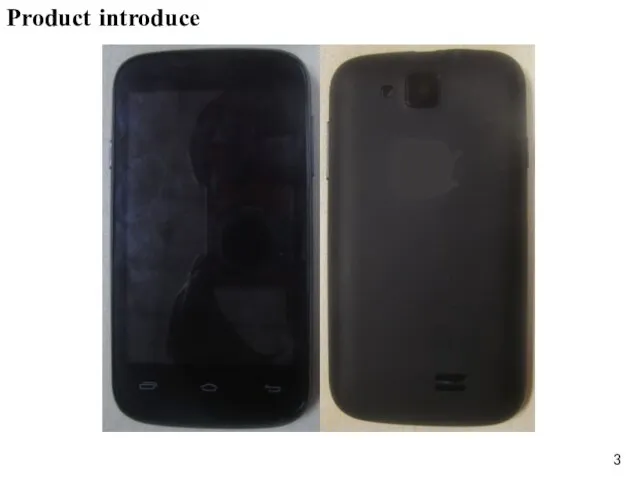
- 3. Product introduce
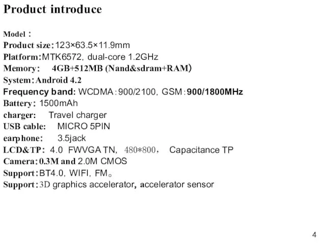
- 4. Product introduce Model : Product size:123×63.5×11.9mm Platform:MTK6572,dual-core 1.2GHz Memory: 4GB+512MB (Nand&sdram+RAM) System:Android 4.2 Frequency band: WCDMA:900/2100,GSM:900/1800MHz
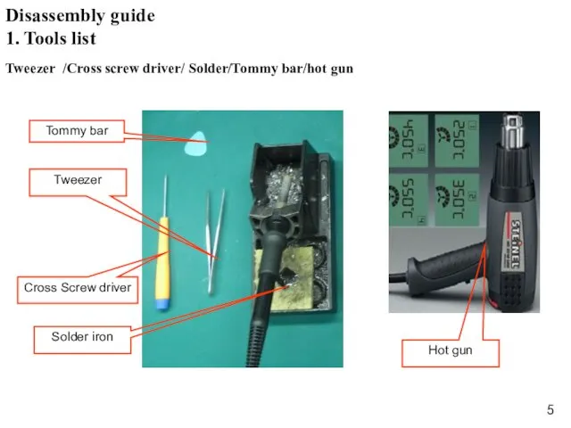
- 5. Hot gun 1. Tools list Tweezer /Cross screw driver/ Solder/Tommy bar/hot gun Disassembly guide
- 6. 2. Battery caver disassembly open the battery cover,as the Fig. 1 Fig. 1 Disassembly guide Battery
- 7. 3. Back caver disassembly 1) Unscrew 10 screws in back cover ,as the Fig.2; Fig. 2
- 8. Fig. 3 2) Disassemble back cover with Tommy bar ,as the Fig.3; Disassembly guide Back cover
- 9. 4.Main board and front cover disassembly 1)The main components of distribution,as the fig.4; Fig.4 Disassembly guide
- 10. 2)remove two screws and open the LCD con.& TP con. ,and remove the volume key FPC
- 11. 3) Disassemble the main board.as the FIG.6 Fig.6 Disassembly guide
- 12. 5. Front and Back camera & Flash FPC & Side key FPC & MIC &Camera bracket
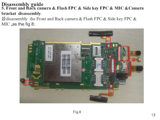
- 13. Disassembly guide 5. Front and Back camera & Flash FPC & Side key FPC & MIC
- 14. Fig.9 remove the Speaker and receiver and Vibration,as the FIG.9; 6. Speaker & receiver & Vibration
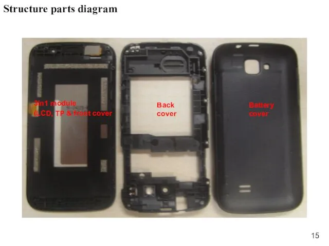
- 15. Structure parts diagram 3in1 module (LCD, TP & front cover Back cover Battery cover
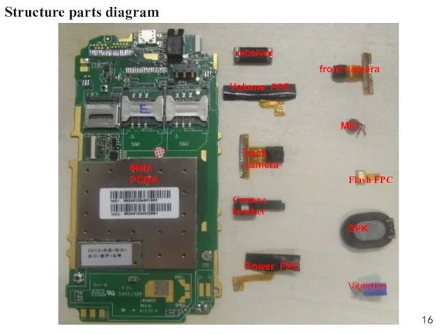
- 16. Structure parts diagram Main PCBA Vibration back camera front camera receiver Power FPC MIC Camera bracket
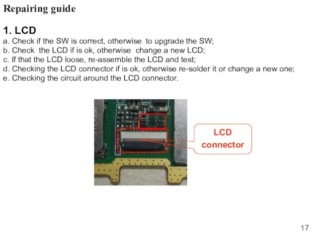
- 17. Repairing guide 1. LCD a. Check if the SW is correct, otherwise to upgrade the SW;
- 18. 2. Camera a. Checking the camera is assemble ok, re-assemble the camera and test; b. Using
- 19. 3. TP a. Checking the SW and upgrade the SW; b. Checking the FPC of TP
- 20. 4.Ring a. Checking the shrapnel of speaker if is ok; b. Checking the resistance of speaker
- 21. 5.receiver a. Checking the shrapnel of receiver if is ok; b. Checking the resistance of receiver
- 22. a. Checking the MIC and Vibrator is cold soldering, re-solder it; b. Change the MIC and
- 23. a. Checking the shrapnel of earphone if is ok; b. Checking the connector point on the
- 24. a. Checking the voltage of battery if is 3.8-4.2V and connect ok; b. Upgrade the SW;
- 25. a. Checking the voltage of battery if is over 3.4V; b. Checking the charger and USB
- 26. Checking the connector of T –card and SIM card; Change the connector of T –card and
- 27. a. Checking RF line if that is broken; b. Checking RF line assemble if is ok;
- 29. Скачать презентацию
content
1、 Product introduce..………..p3-p4
2、 Disassembly guide ……….p5-p17
3、Structure parts diagram…..p18
content
1、 Product introduce..………..p3-p4
2、 Disassembly guide ……….p5-p17
3、Structure parts diagram…..p18
Product introduce
Product introduce
Product introduce
Model :
Product size:123×63.5×11.9mm
Platform:MTK6572,dual-core 1.2GHz
Memory: 4GB+512MB (Nand&sdram+RAM)
System:Android 4.2
Frequency band: WCDMA:900/2100,GSM:900/1800MHz
Battery:
Product introduce
Model :
Product size:123×63.5×11.9mm
Platform:MTK6572,dual-core 1.2GHz
Memory: 4GB+512MB (Nand&sdram+RAM)
System:Android 4.2
Frequency band: WCDMA:900/2100,GSM:900/1800MHz
Battery:
Hot gun
1. Tools list
Tweezer /Cross screw driver/ Solder/Tommy bar/hot gun
Disassembly
Hot gun
1. Tools list
Tweezer /Cross screw driver/ Solder/Tommy bar/hot gun
Disassembly
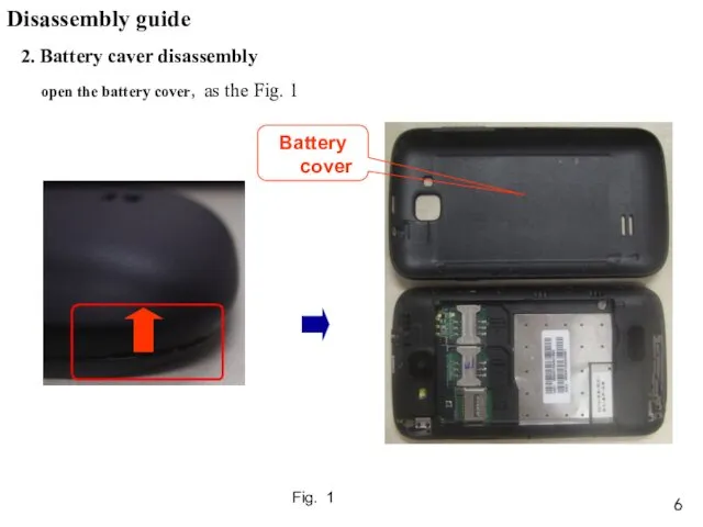
2. Battery caver disassembly
open the battery cover,as the Fig. 1
Fig. 1
Disassembly
2. Battery caver disassembly
open the battery cover,as the Fig. 1
Fig. 1
Disassembly

3. Back caver disassembly
1) Unscrew 10 screws in back cover ,as
3. Back caver disassembly
1) Unscrew 10 screws in back cover ,as
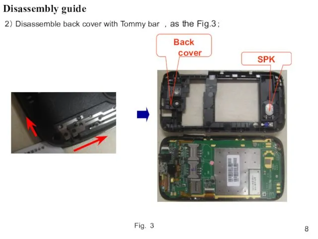
Fig. 3
2) Disassemble back cover with Tommy bar ,as the Fig.3;
Disassembly
Fig. 3
2) Disassemble back cover with Tommy bar ,as the Fig.3;
Disassembly
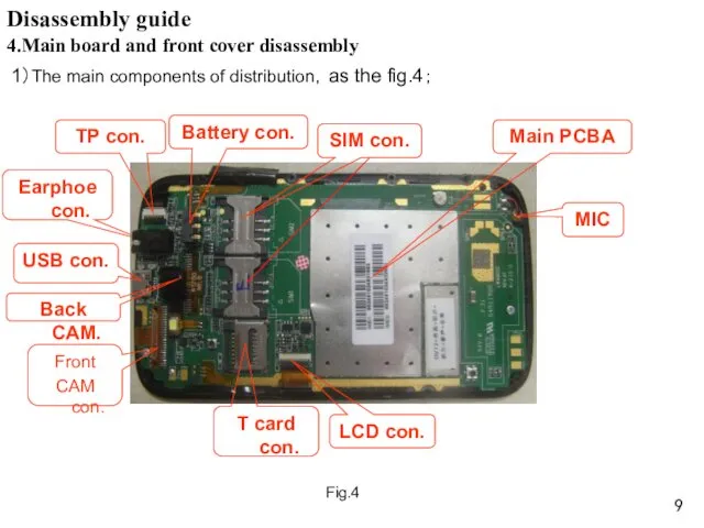
4.Main board and front cover disassembly
1)The main components of distribution,as
4.Main board and front cover disassembly
1)The main components of distribution,as
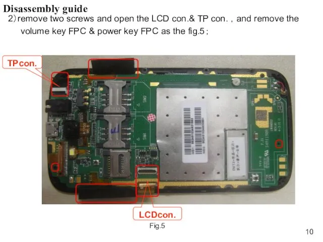
2)remove two screws and open the LCD con.& TP con.
2)remove two screws and open the LCD con.& TP con.
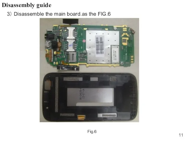
3) Disassemble the main board.as the FIG.6
Fig.6
Disassembly guide
3) Disassemble the main board.as the FIG.6
Fig.6
Disassembly guide
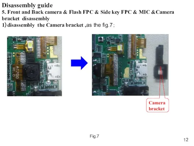
5. Front and Back camera & Flash FPC & Side key
5. Front and Back camera & Flash FPC & Side key
Disassembly guide
5. Front and Back camera & Flash FPC & Side
Disassembly guide
5. Front and Back camera & Flash FPC & Side
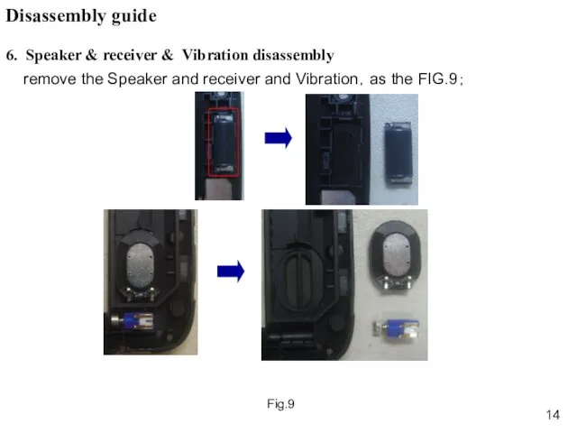
Fig.9
remove the Speaker and receiver and Vibration,as the FIG.9;
6. Speaker
Fig.9
remove the Speaker and receiver and Vibration,as the FIG.9;
6. Speaker
Structure parts diagram
3in1 module
(LCD, TP & front cover
Back cover
Battery cover
Structure parts diagram
3in1 module
(LCD, TP & front cover
Back cover
Battery cover
Structure parts diagram
Main PCBA
Vibration
back camera
front camera
receiver
Power FPC
MIC
Camera bracket
Flash FPC
Volume FPC
SPK
Structure parts diagram
Main PCBA
Vibration
back camera
front camera
receiver
Power FPC
MIC
Camera bracket
Flash FPC
Volume FPC
SPK
Repairing guide
1. LCD
a. Check if the SW is correct, otherwise to
Repairing guide
1. LCD
a. Check if the SW is correct, otherwise to
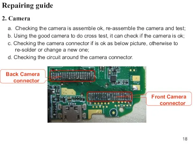
2. Camera
a. Checking the camera is assemble ok, re-assemble the camera
2. Camera
a. Checking the camera is assemble ok, re-assemble the camera
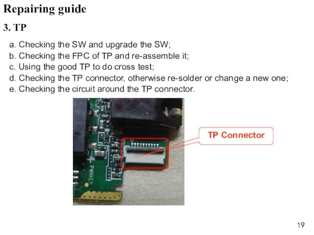
3. TP
a. Checking the SW and upgrade the SW;
b. Checking the
3. TP
a. Checking the SW and upgrade the SW;
b. Checking the
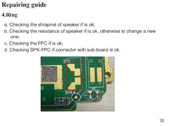
4.Ring
a. Checking the shrapnel of speaker if is ok;
b. Checking the
4.Ring
a. Checking the shrapnel of speaker if is ok;
b. Checking the
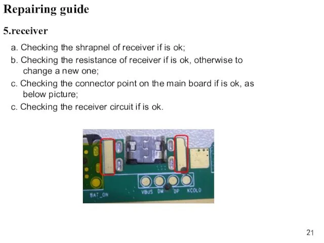
5.receiver
a. Checking the shrapnel of receiver if is ok;
b. Checking
5.receiver
a. Checking the shrapnel of receiver if is ok;
b. Checking
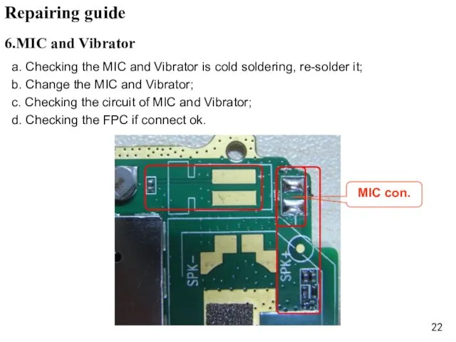
a. Checking the MIC and Vibrator is cold soldering, re-solder it;
b.
a. Checking the MIC and Vibrator is cold soldering, re-solder it;
b.
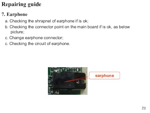
a. Checking the shrapnel of earphone if is ok;
b. Checking the
a. Checking the shrapnel of earphone if is ok;
b. Checking the
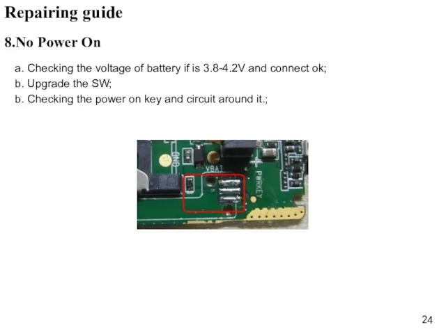
a. Checking the voltage of battery if is 3.8-4.2V and connect
a. Checking the voltage of battery if is 3.8-4.2V and connect
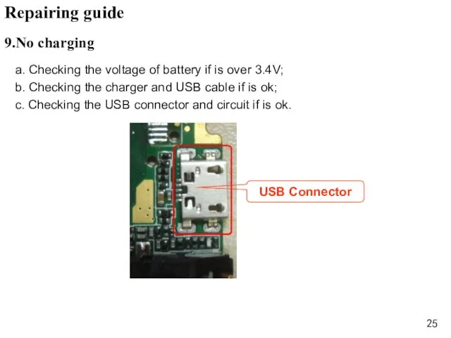
a. Checking the voltage of battery if is over 3.4V;
b. Checking
a. Checking the voltage of battery if is over 3.4V;
b. Checking
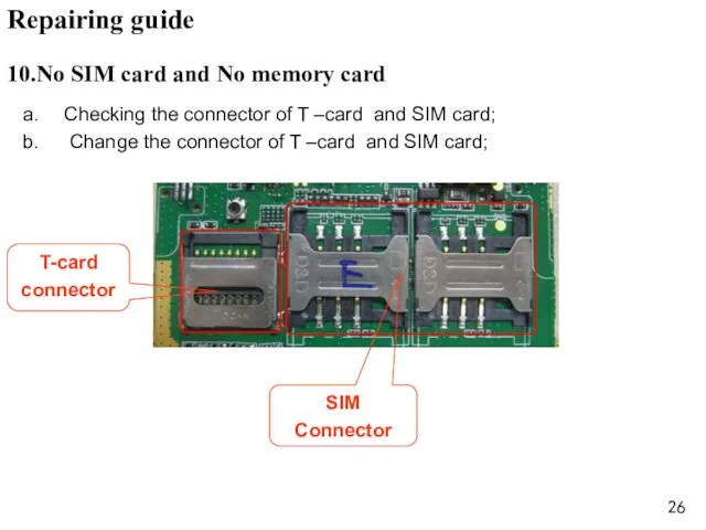
Checking the connector of T –card and SIM card;
Change the
Checking the connector of T –card and SIM card;
Change the
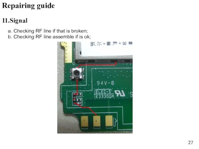
a. Checking RF line if that is broken;
b. Checking RF
a. Checking RF line if that is broken;
b. Checking RF
 : Особенности формирования произвольного внимания у детей 4-5 лет.
 Пороки вкуса и запаха
 Uterine sarcoma
 Учебно-методическое пособие Учимся считать на английском языке
 Мотовилихинская артиллерия в Афганистане
 Әсіпорынның архитектуралық құрылыс
 керамика66
 презентация мы здоровыми растем (2).ppt
 Полімери. Застосування
 Hydraulic Fracturing
 Политическая система общества
 Цифровые автоматы и регистры, счетчики
 Работа с поролоном. Поросенок
 Музей Приокского района. Детские программы
 Обобщение опыта Роль музыкально-дидактических игр в становлении ребенка Диск
 Операции над графами и их свойства
 РАЗВИВАЮЩАЯ СРЕДА В КОРРЕКЦИОННОЙ ГРУППЕ ЗНАЙКИ ПО ФГОС
 Внеклассное мероприятие У природы нет плохой погоды
 Использование информационных компьютерных технологий на уроках биологии
 Презентация Рассказы и сказки Н. Носова
 Объемно-планировочная структура многоэтажного жилого здания
 bd3ccfe5c6d24bb9a8b4ece584a2830f
 Моя семья. Екатерина Багринцева
 Инерция. Билет 2
 6 класс. Гидросфера 3 урок. Части мирового океана
 Проект в ДОУ
 Буква Э
 История развития телевидения