- Samsung For LED TV UE4,5 Series Training manual

Содержание
- 2. Ⅰ. Concept Ⅱ. Specification Ⅲ. Product Image Ⅳ. Inner Feature Ⅴ. Disassemble Ⅵ. Troubleshooting Ⅶ. Feature
- 3. Ⅰ. Product Concept “The Most Affordable LED TV ever” Picture Quality : Direct LED backlighting Panel
- 4. Ⅱ. Specification -3/23-
- 5. Ⅱ. Specification -3/23-
- 6. Ⅱ. Specification -3/23- Spec. Comparison
- 7. Ⅱ. Specification -3/23- Spec. Comparison
- 8. Ⅲ. Design TV Controller
- 9. Ⅲ. Design Plug & Play
- 10. Ⅲ. Design Plug & Play
- 11. Ⅲ. Design Plug & Play
- 12. Ⅲ. Design Connectios
- 13. Ⅲ. Design Connectios
- 14. Ⅲ. Design Changing the Input Source
- 15. Ⅲ. Design Display Modes(HDMI/DVI)
- 16. Ⅲ. Design Remote Control
- 17. Ⅲ. Design Viewing Front – UE22ES5000 -Speakers - Remote Control Sensor - Power Indicator - Jog
- 18. Ⅲ. Design Rear – UE22ES5000
- 19. Ⅲ. Design Viewing Front - UE32EH5000 -Speakers - Remote Control Sensor - Power Indicator - Jog
- 20. Ⅲ. Design Rear - UE32EH5000
- 21. Ⅲ. Design Viewing Front - UE40EH5000 - Speakers - Remote Control Sensor - Power Indicator -
- 22. Ⅲ. Design Rear - UE40EH5000
- 23. Ⅲ. Design Viewing Front - UE46EH5000 -Speakers - Remote Control Sensor - Power Indicator - Jog
- 24. Ⅲ. Design Rear - UE46EH5000
- 25. Ⅲ. Design Viewing Front – UE19ES4000 -Speakers - Remote Control Sensor - Power Indicator - Jog
- 26. Ⅲ. Design Rear – UE19ES4000
- 27. Ⅲ. Design Viewing Front - UE26EH4000 -Speakers - Remote Control Sensor - Power Indicator - Jog
- 28. Ⅲ. Design Rear – UE26EH4000
- 29. Ⅲ. Design Viewing Front - UE32EH4000 - Speakers - Remote Control Sensor - Power Indicator -
- 30. Ⅲ. Design Rear - UE32EH4000
- 31. Ⅳ. Inner Feature LAY OUT – UE19ES5000 Main Board SMPS Board Speaker (R) Speaker (L)
- 32. Ⅳ. Inner Feature LAY OUT – UE32EH5000 Main Board SMPS Board Speaker (R) Speaker (L)
- 33. Ⅳ. Inner Feature LAY OUT – UE40EH5000 Main Board SMPS Board Speaker (R) Speaker (L)
- 34. Ⅳ. Inner Feature LAY OUT – UE46EH5000 Main Board SMPS Board Speaker (R) Speaker (L)
- 35. Ⅳ. Inner Feature LAY OUT – UE19ES4000 Main Board SMPS Board Speaker (R) Speaker (L)
- 36. Ⅳ. Inner Feature Main Board SMPS Board Speaker (R) Speaker (L) LAY OUT – UE26EH4000
- 37. Main Board SMPS Board Speaker (R) Speaker (L) Ⅳ. Inner Feature LAY OUT – UE32EH4000
- 38. Ⅳ. Inner Feature Wiring Diagram
- 39. Ⅳ. Inner Feature RESET TREE SEMS 23 (Mstar X9) SMPS Standby B+ Power SW_POWER POWER_DET PANEL
- 40. Ⅳ. Inner Feature I2C SEMS23 (MSTAR X9) UART_RX2/GPIO44 UART_TX2/GPIO43 DDCR_CK DDCR_DA AT24C256 (0xA0) SCL_EEPROM SDA_EEPROM TUNER
- 41. Ⅳ. Inner Feature POWER TREE
- 42. Ⅳ. Inner Feature POWER TREE
- 43. Ⅳ. Inner Feature Main Board Layout
- 44. Ⅳ. Inner Feature Main Board Conn. Pin map
- 45. Ⅳ. Inner Feature Main Board Conn. Pin map
- 46. Ⅳ. Inner Feature Main Board Conn. Pin map
- 47. Ⅳ. Inner Feature Main Board Conn. Pin map
- 48. Ⅴ. Disassembly Place monitor face down on cushioned table. 2. Remove 4 screws from the stand.
- 49. Ⅴ. Disassembly 3. Remove stand. 4. 32/40" : Remove 1 screw of cover jack 46" :
- 50. Ⅴ. Disassembly 5. 32/40" : Remove the cover jack 46" : Remove the rear cover. 6.
- 51. Ⅴ. Disassembly 7. Remove the screws of rear-cover. 8. Remove the rear-cover. 40 32 46 46
- 52. Ⅴ. Disassembly 9.Remove the screws of main board and IP board and Panel. 10. Remove the
- 53. Ⅴ. Disassembly 11. Remove the LVDS cable and Panel drive cable 12. Completed disassembly
- 54. Ⅴ. Disassembly Place monitor face down on cushioned table. 2. Remove 4 screws from the stand.
- 55. Ⅴ. Disassembly 3. Remove stand. 4. Remove the 1 screw of cover jack
- 56. Ⅴ. Disassembly 5. Remove the cover jack. 6. Disconnect the function assy cable..
- 57. Ⅴ. Disassembly 7. Remove the screws of rear-cover. 8. Remove the rear-cover. 32 26
- 58. Ⅴ. Disassembly 9.Remove the screws of main board and IP board and Panel. 10. Remove the
- 59. Ⅴ. Disassembly 11. Remove the LVDS cable and Panel drive cable 12. Completed disassembly
- 60. Ⅴ. Disassembly(PTC) 1. Place monitor face up on cushioned table. 2. remove the T-CON Cover
- 61. Ⅴ. Disassembly(PTC) 3. first spread the PTC upper 4. Spread the both sides of PTC upper
- 62. Ⅴ. Disassembly(PTC) 5. Apart left and right sides of PTC 6. Raise up the PTC bottom
- 63. Ⅴ. Disassembly(PTC) 7. Disassembly is complete.
- 64. Ⅴ. Reassembly(PTC) 1. Cover the PTC bottom 2. Combine the hook of left and right side
- 65. Ⅴ. Disassembly(PTC) 3. Check to combine the top and bottom ※caution ※ Combine to stuck the
- 66. Ⅴ. Disassembly(PTC) 3. Check to combine the top and bottom
- 67. Ⅴ. Disassembly(PTC) ※caution ※ Combine to stuck the PTC Rib in middle molde
- 68. Ⅴ. Disassembly(PTC) 4. Disassembly is complete.
- 69. Ⅵ. Trouble Shooting Check List for Initial operation
- 70. Ⅵ. Trouble Shooting No power AND No Video
- 71. Ⅵ. Trouble Shooting No power AND No Video
- 72. Ⅵ. Trouble Shooting No power AND No Video
- 73. Ⅵ. Trouble Shooting RS232C code
- 74. Ⅵ. Trouble Shooting Calibration
- 75. Ⅵ. Trouble Shooting Calibration
- 76. Ⅵ. Trouble Shooting White Balance
- 77. Ⅵ. Trouble Shooting How to check the SW version
- 78. Ⅵ. Trouble Shooting How to check the SW version
- 79. Ⅵ. Trouble Shooting USB Download
- 80. Ⅵ. Trouble Shooting USB Download
- 81. Ⅵ. Trouble Shooting USB Download
- 83. Скачать презентацию
 Невербальные средства общения
 Астраханское ханство
 Дұрыс тамақтану пирамидасы
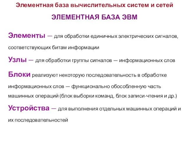 Элементная база вычислительных систем и сетей
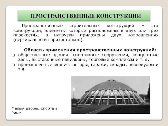 Пространственные конструкции
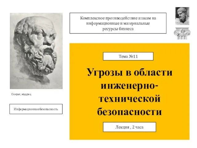 Угрозы в области инженерно-технической безопасности
 Регулирование территориальных сетевых организаций
 Классный час на тему : Моя малая родина
 Проблема общественного контроля над властью
 Архитектура персонального компьютера. Классификация программных средств. (Лекция 3)
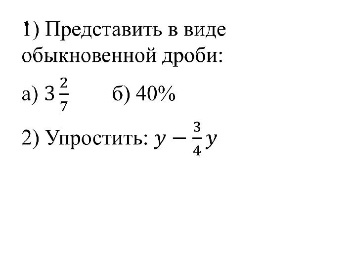 Презентация к уроку по теме Дробные выражения
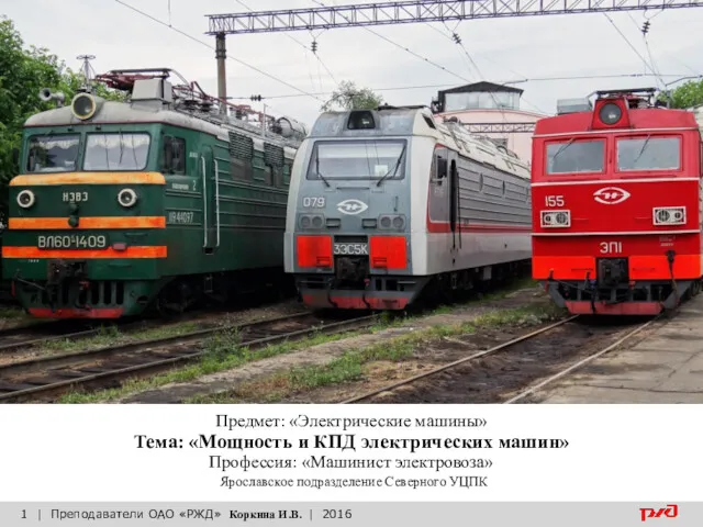 Мощность и КПД электрических машин
 Балық және балық өнімдерін алу технологиясы
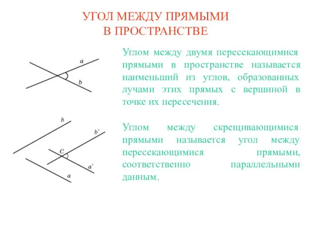 Угол между прямыми в пространстве
 Основы медицинской генетики
 Артикуляционная считалка № 5
 Презентация по технологической практике на ЖД станции Кобрин
 Федерация современного мечевого боя России
 Логические элементы на полевых транзисторах
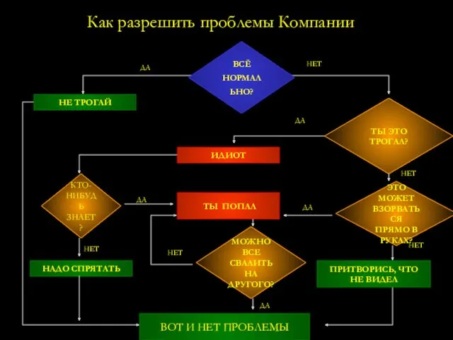 Как разрешить проблемы компании
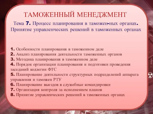 Процесс планирования в таможенных органах. Принятие управленческих решений в таможенных органах. Тема 7
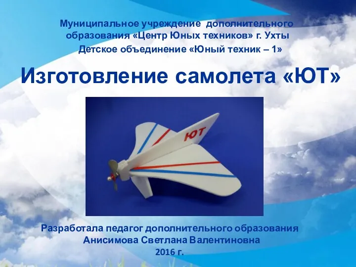 Изготовление самолета Юный техник
 Schleswig-Holzstein
 Осторожно тонкий лёд
 Векторы. Равенство векторов
 Пневматический транспорт. Применение, достоинства и недостатки
 Психофизическое развитие подростков (трудный возраст)
 Шаблон проекта