- Self-ameliorating inkjet printed composites

Содержание
- 2. Self-ameliorating inkjet printed composites for higher survivability www.sheffieldcomposites.co.uk Composites At Sheffield. © 2013 The University Of
- 3. www.sheffieldcomposites.co.uk Composites At Sheffield. Benefits of Inkjet Printing Direct write technology (no masks needed) Additive technology
- 4. www.sheffieldcomposites.co.uk Composites At Sheffield. Drop on Demand Printheads Heater © 2013 The University Of Sheffield
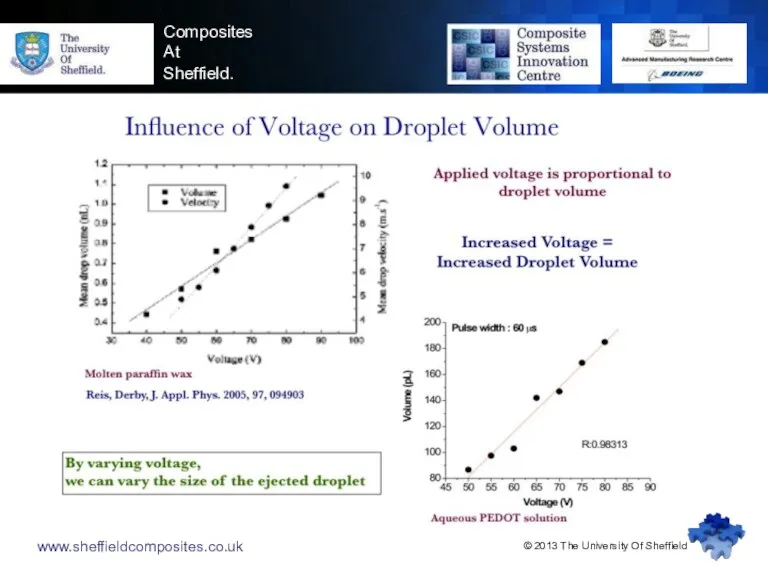
- 5. www.sheffieldcomposites.co.uk Composites At Sheffield. © 2013 The University Of Sheffield 1 Optimum printing
- 6. www.sheffieldcomposites.co.uk Composites At Sheffield. © 2013 The University Of Sheffield
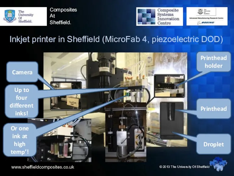
- 7. www.sheffieldcomposites.co.uk Composites At Sheffield. Inkjet printer in Sheffield (MicroFab 4, piezoelectric DOD) Up to four different
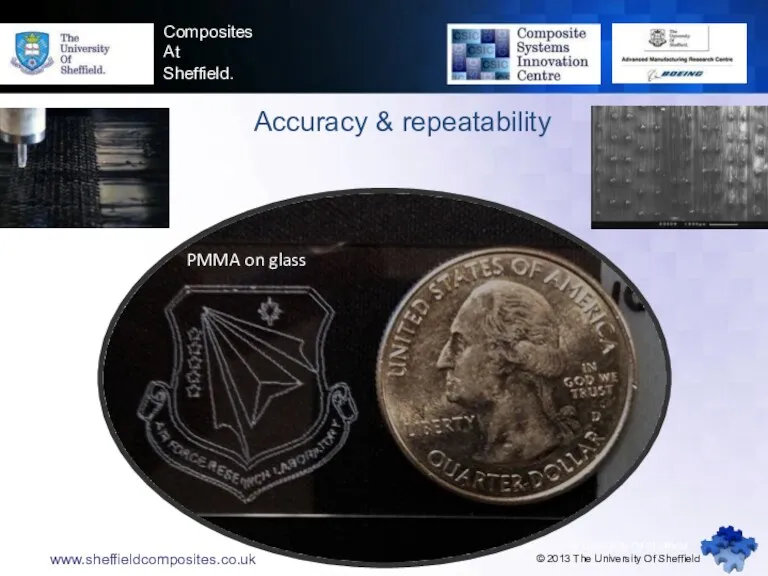
- 8. www.sheffieldcomposites.co.uk Accuracy & repeatability © 2013 The University Of Sheffield Composites At Sheffield. www.sheffieldcomposites.co.uk © 2013
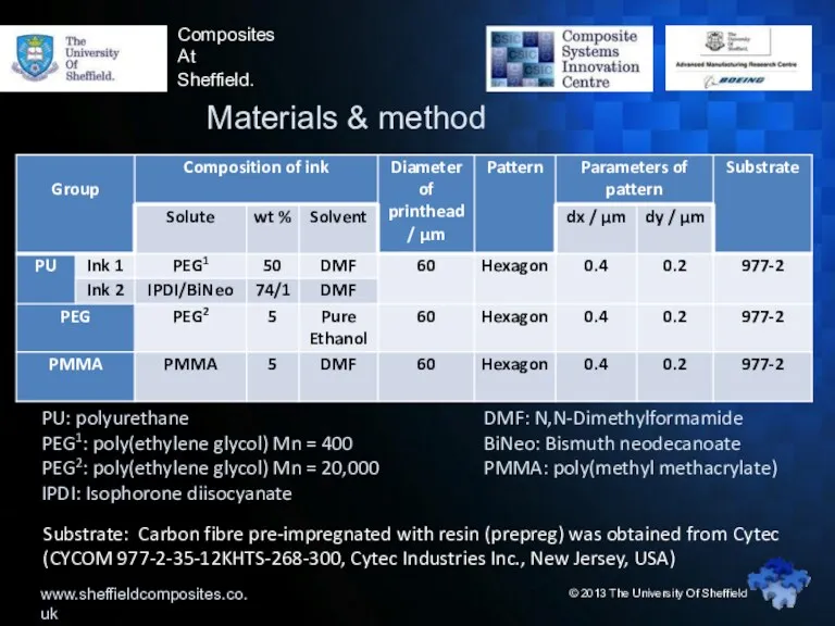
- 9. www.sheffieldcomposites.co.uk Composites At Sheffield. Materials & method © 2013 The University Of Sheffield PU: polyurethane PEG1:
- 10. www.sheffieldcomposites.co.uk Composites At Sheffield. Pattern – Hexagon hexagon © 2013 The University Of Sheffield %S ~40%
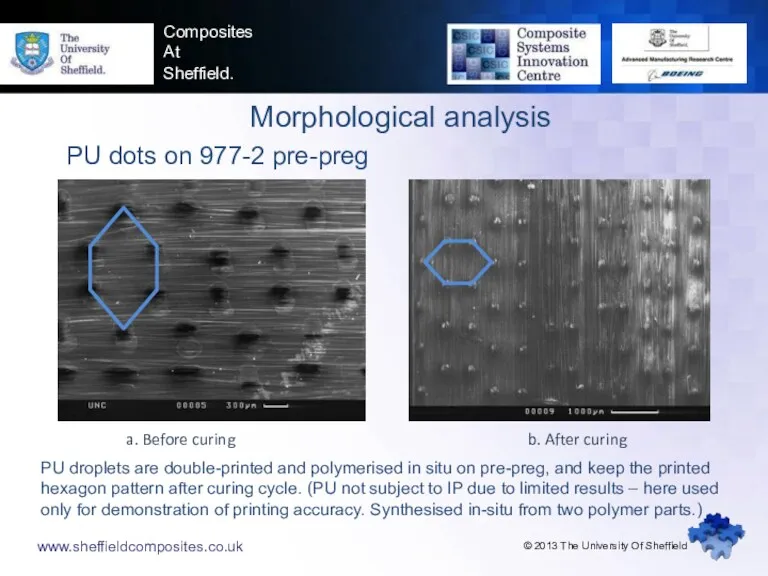
- 11. www.sheffieldcomposites.co.uk Composites At Sheffield. Morphological analysis PU dots on 977-2 pre-preg a. Before curing b. After
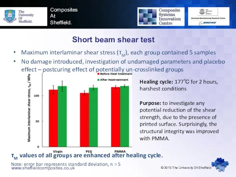
- 12. www.sheffieldcomposites.co.uk Composites At Sheffield. Short beam shear test Maximum interlaminar shear stress (τM), each group contained
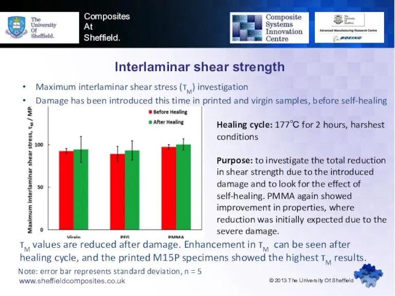
- 13. www.sheffieldcomposites.co.uk Composites At Sheffield. Interlaminar shear strength Maximum interlaminar shear stress (τM) investigation Damage has been
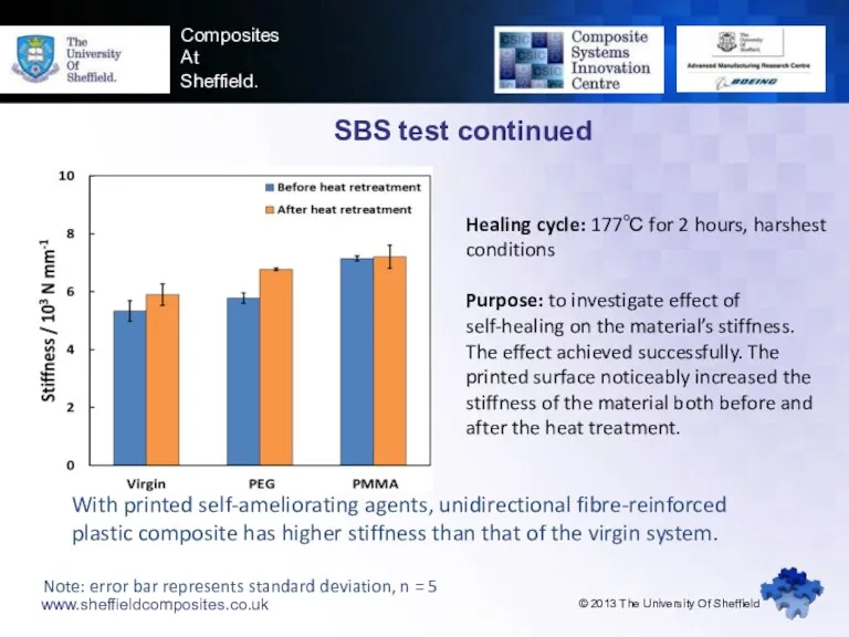
- 14. www.sheffieldcomposites.co.uk Composites At Sheffield. SBS test continued With printed self-ameliorating agents, unidirectional fibre-reinforced plastic composite has
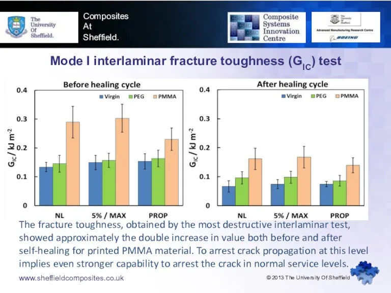
- 15. www.sheffieldcomposites.co.uk Composites At Sheffield. Mode I interlaminar fracture toughness (GIC) test The fracture toughness, obtained by
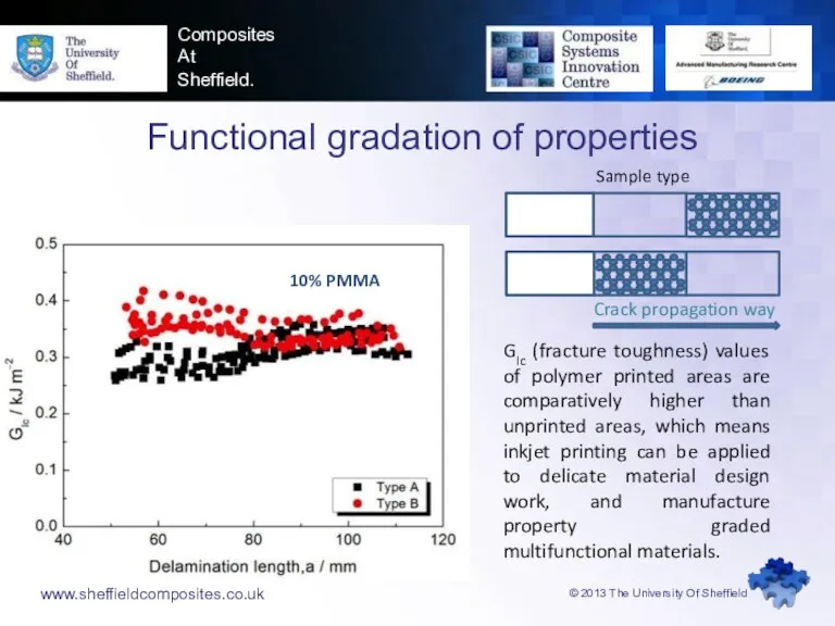
- 16. www.sheffieldcomposites.co.uk © 2013 The University Of Sheffield Composites At Sheffield. GIc (fracture toughness) values of polymer
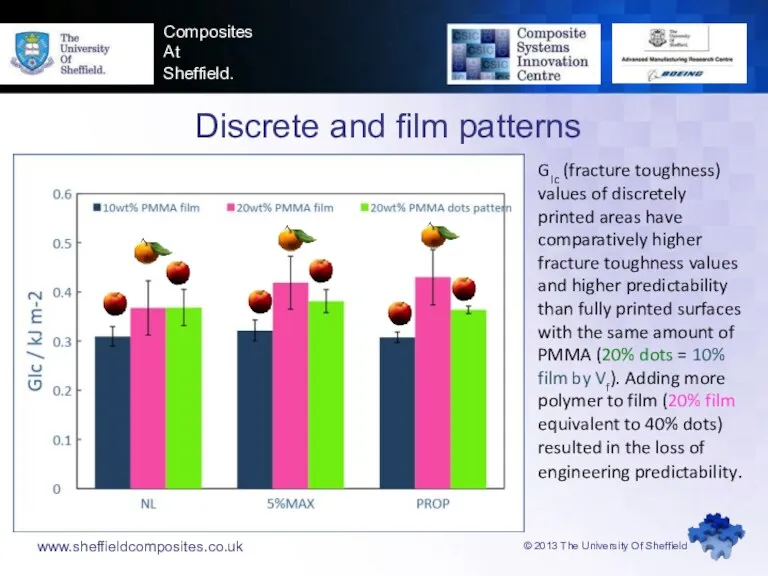
- 17. www.sheffieldcomposites.co.uk © 2013 The University Of Sheffield Composites At Sheffield. GIc (fracture toughness) values of discretely
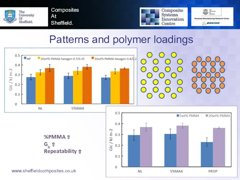
- 18. www.sheffieldcomposites.co.uk © 2013 The University Of Sheffield Composites At Sheffield. Patterns and polymer loadings %PMMA ⇧
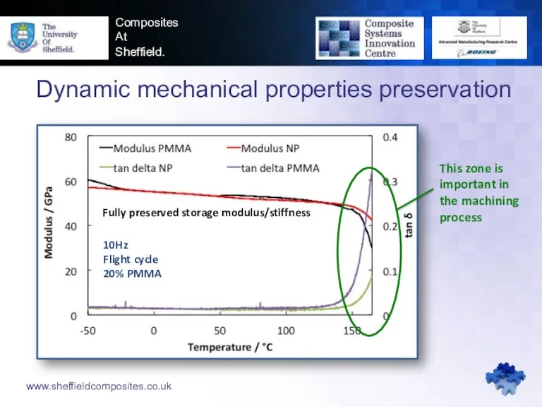
- 19. www.sheffieldcomposites.co.uk Composites At Sheffield. Dynamic mechanical properties preservation 10Hz Flight cycle 20% PMMA This zone is
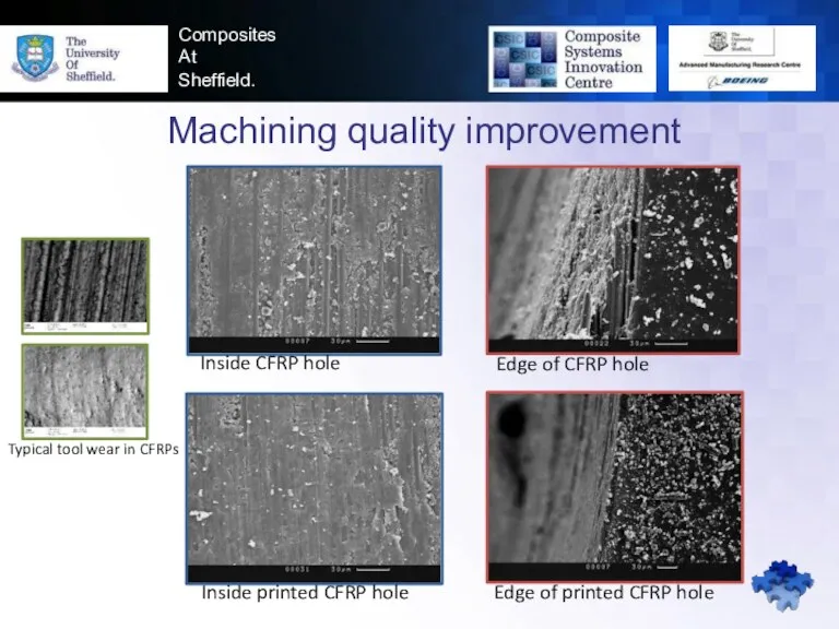
- 20. Composites At Sheffield. Machining quality improvement Inside CFRP hole Edge of CFRP hole Inside printed CFRP
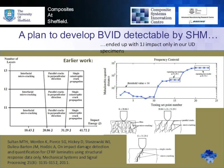
- 21. Composites At Sheffield. A plan to develop BVID detectable by SHM… Sultan MTH, Worden K, Pierce
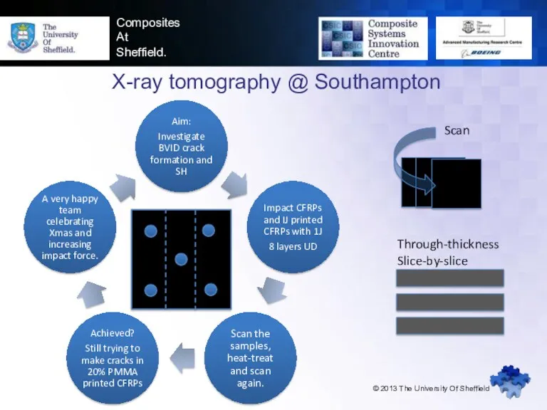
- 22. Composites At Sheffield. X-ray tomography @ Southampton © 2013 The University Of Sheffield Scan Through-thickness Slice-by-slice
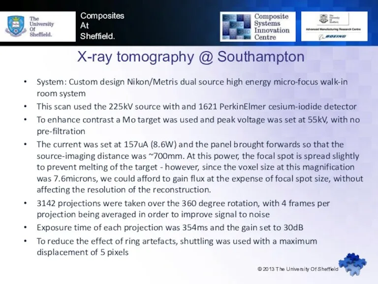
- 23. Composites At Sheffield. X-ray tomography @ Southampton © 2013 The University Of Sheffield System: Custom design
- 24. Composites At Sheffield.
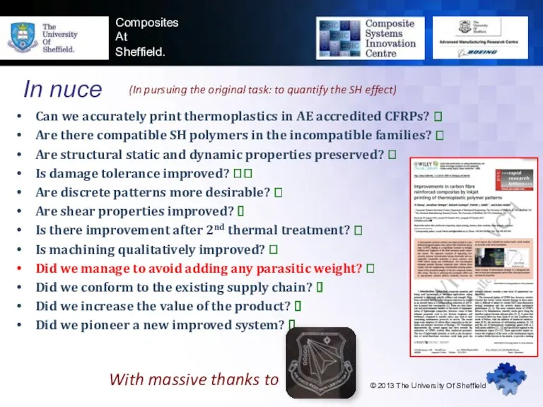
- 25. Composites At Sheffield. In nuce © 2013 The University Of Sheffield Can we accurately print thermoplastics
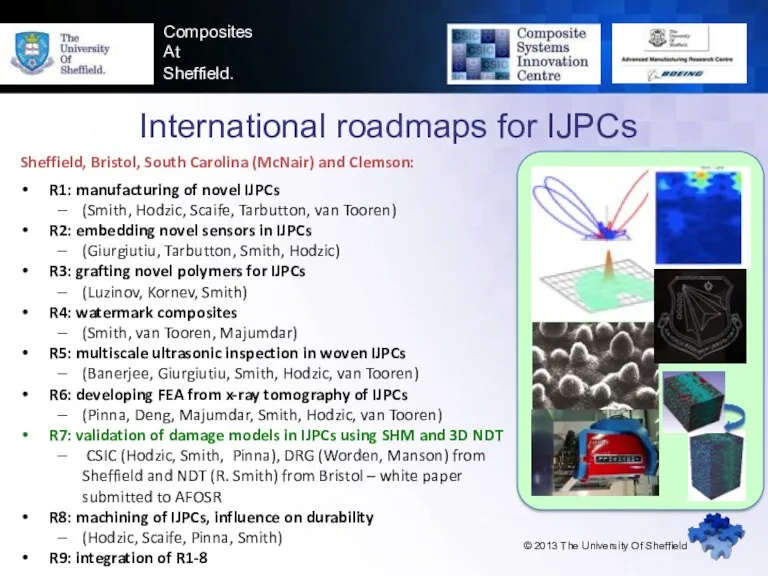
- 26. Composites At Sheffield. International roadmaps for IJPCs © 2013 The University Of Sheffield Sheffield, Bristol, South
- 27. Innovation and Research Manufacture/Characterization/Certification Center for Mechanics, Materials, and Non-Destructive Evaluation Laboratory for Active Materials and
- 29. Скачать презентацию
Self-ameliorating inkjet printed composites for higher survivability
www.sheffieldcomposites.co.uk
Composites
At
Sheffield.
© 2013 The
Self-ameliorating inkjet printed composites for higher survivability
www.sheffieldcomposites.co.uk
Composites
At
Sheffield.
© 2013 The
www.sheffieldcomposites.co.uk
Composites
At
Sheffield.
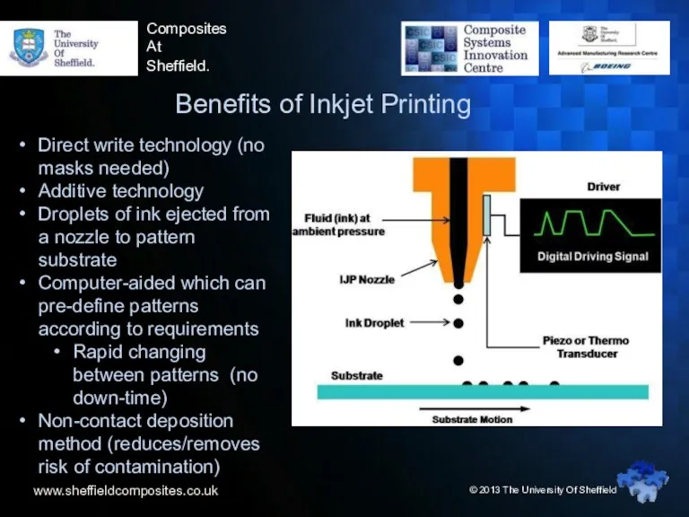
Benefits of Inkjet Printing
Direct write technology (no masks
www.sheffieldcomposites.co.uk
Composites
At
Sheffield.
Benefits of Inkjet Printing
Direct write technology (no masks
www.sheffieldcomposites.co.uk
Composites
At
Sheffield.
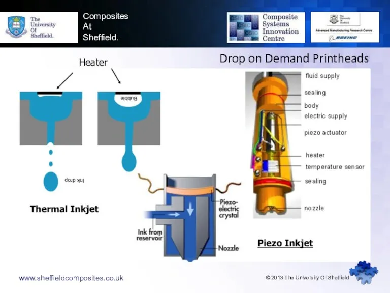
Drop on Demand Printheads
Heater
© 2013 The University Of Sheffield
www.sheffieldcomposites.co.uk
Composites
At
Sheffield.
Drop on Demand Printheads
Heater
© 2013 The University Of Sheffield
www.sheffieldcomposites.co.uk
Composites
At
Sheffield.
© 2013 The University Of Sheffield
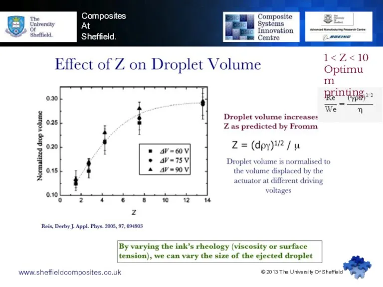
1 < Z <
www.sheffieldcomposites.co.uk
Composites
At
Sheffield.
© 2013 The University Of Sheffield
1 < Z <
www.sheffieldcomposites.co.uk
Composites
At
Sheffield.
© 2013 The University Of Sheffield
www.sheffieldcomposites.co.uk
Composites
At
Sheffield.
© 2013 The University Of Sheffield
www.sheffieldcomposites.co.uk
Composites
At
Sheffield.
Inkjet printer in Sheffield (MicroFab 4, piezoelectric DOD)
Up to
www.sheffieldcomposites.co.uk
Composites
At
Sheffield.
Inkjet printer in Sheffield (MicroFab 4, piezoelectric DOD)
Up to
www.sheffieldcomposites.co.uk
Accuracy & repeatability
© 2013 The University Of Sheffield
Composites
At
Sheffield.
www.sheffieldcomposites.co.uk
© 2013
www.sheffieldcomposites.co.uk
Accuracy & repeatability
© 2013 The University Of Sheffield
Composites
At
Sheffield.
www.sheffieldcomposites.co.uk
© 2013
www.sheffieldcomposites.co.uk
Composites
At
Sheffield.
Materials & method
© 2013 The University Of Sheffield
PU: polyurethane
PEG1:
www.sheffieldcomposites.co.uk
Composites
At
Sheffield.
Materials & method
© 2013 The University Of Sheffield
PU: polyurethane
PEG1:
www.sheffieldcomposites.co.uk
Composites
At
Sheffield.
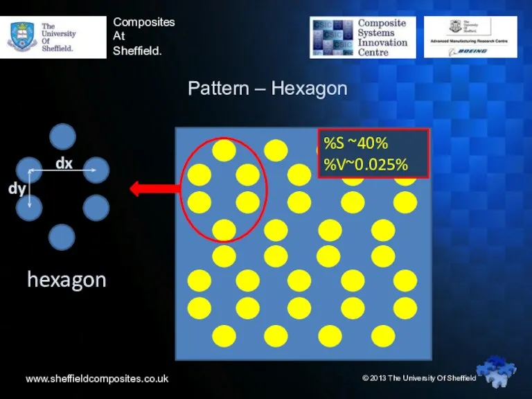
Pattern – Hexagon
hexagon
© 2013 The University Of Sheffield
%S
www.sheffieldcomposites.co.uk
Composites
At
Sheffield.
Pattern – Hexagon
hexagon
© 2013 The University Of Sheffield
%S
www.sheffieldcomposites.co.uk
Composites
At
Sheffield.
Morphological analysis
PU dots on 977-2 pre-preg
a. Before curing
www.sheffieldcomposites.co.uk
Composites
At
Sheffield.
Morphological analysis
PU dots on 977-2 pre-preg
a. Before curing
www.sheffieldcomposites.co.uk
Composites
At
Sheffield.
Short beam shear test
Maximum interlaminar shear stress (τM), each
www.sheffieldcomposites.co.uk
Composites
At
Sheffield.
Short beam shear test
Maximum interlaminar shear stress (τM), each
www.sheffieldcomposites.co.uk
Composites
At
Sheffield.
Interlaminar shear strength
Maximum interlaminar shear stress (τM) investigation
Damage has
www.sheffieldcomposites.co.uk
Composites
At
Sheffield.
Interlaminar shear strength
Maximum interlaminar shear stress (τM) investigation
Damage has
www.sheffieldcomposites.co.uk
Composites
At
Sheffield.
SBS test continued
With printed self-ameliorating agents, unidirectional fibre-reinforced plastic
www.sheffieldcomposites.co.uk
Composites
At
Sheffield.
SBS test continued
With printed self-ameliorating agents, unidirectional fibre-reinforced plastic
www.sheffieldcomposites.co.uk
Composites
At
Sheffield.
Mode I interlaminar fracture toughness (GIC) test
The fracture toughness,
www.sheffieldcomposites.co.uk
Composites
At
Sheffield.
Mode I interlaminar fracture toughness (GIC) test
The fracture toughness,
www.sheffieldcomposites.co.uk
© 2013 The University Of Sheffield
Composites
At
Sheffield.
GIc (fracture toughness) values
www.sheffieldcomposites.co.uk
© 2013 The University Of Sheffield
Composites
At
Sheffield.
GIc (fracture toughness) values
www.sheffieldcomposites.co.uk
© 2013 The University Of Sheffield
Composites
At
Sheffield.
GIc (fracture toughness) values
www.sheffieldcomposites.co.uk
© 2013 The University Of Sheffield
Composites
At
Sheffield.
GIc (fracture toughness) values
www.sheffieldcomposites.co.uk
© 2013 The University Of Sheffield
Composites
At
Sheffield.
Patterns and polymer loadings
%PMMA
www.sheffieldcomposites.co.uk
© 2013 The University Of Sheffield
Composites
At
Sheffield.
Patterns and polymer loadings
%PMMA
www.sheffieldcomposites.co.uk
Composites
At
Sheffield.
Dynamic mechanical properties preservation
10Hz
Flight cycle
20% PMMA
This zone is
important
www.sheffieldcomposites.co.uk
Composites
At
Sheffield.
Dynamic mechanical properties preservation
10Hz
Flight cycle
20% PMMA
This zone is
important
Composites
At
Sheffield.
Machining quality improvement
Inside CFRP hole
Edge of CFRP hole
Inside printed
Composites
At
Sheffield.
Machining quality improvement
Inside CFRP hole
Edge of CFRP hole
Inside printed
Composites
At
Sheffield.
A plan to develop BVID detectable by SHM…
Sultan MTH,
Composites
At
Sheffield.
A plan to develop BVID detectable by SHM…
Sultan MTH,
Composites
At
Sheffield.
X-ray tomography @ Southampton
© 2013 The University Of Sheffield
Scan
Through-thickness
Slice-by-slice
Composites
At
Sheffield.
X-ray tomography @ Southampton
© 2013 The University Of Sheffield
Scan
Through-thickness
Slice-by-slice
Composites
At
Sheffield.
X-ray tomography @ Southampton
© 2013 The University Of Sheffield
System:
Composites
At
Sheffield.
X-ray tomography @ Southampton
© 2013 The University Of Sheffield
System:
Composites
At
Sheffield.
Composites
At
Sheffield.
Composites
At
Sheffield.
In nuce
© 2013 The University Of Sheffield
Can we accurately
Composites
At
Sheffield.
In nuce
© 2013 The University Of Sheffield
Can we accurately
Composites
At
Sheffield.
International roadmaps for IJPCs
© 2013 The University Of Sheffield
Sheffield,
Composites
At
Sheffield.
International roadmaps for IJPCs
© 2013 The University Of Sheffield
Sheffield,
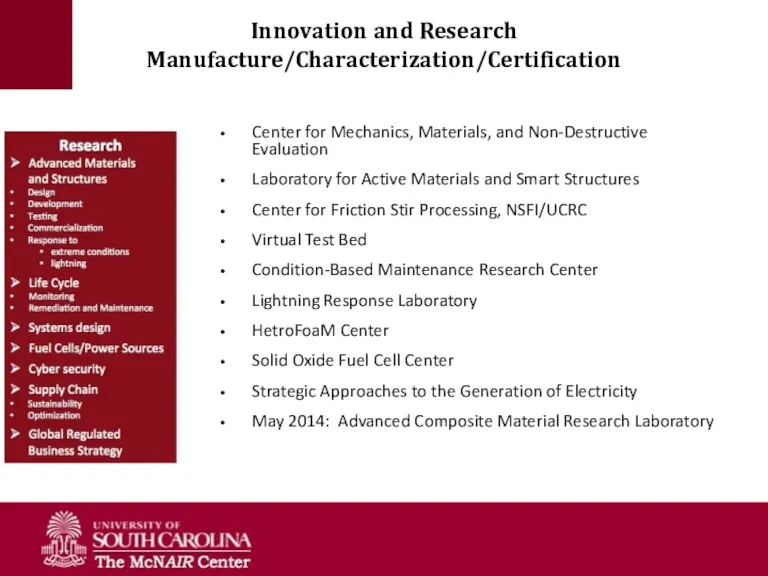
Innovation and Research Manufacture/Characterization/Certification
Center for Mechanics, Materials, and Non-Destructive Evaluation
Laboratory for
Innovation and Research Manufacture/Characterization/Certification
Center for Mechanics, Materials, and Non-Destructive Evaluation
Laboratory for
 Шаблон курсового проекта
 Использование ИКТ в образовательном пространстве ДОУ
 Тема: Здоровый образ жизни.
 Волоховой
 Реконструкция подстанции 110/10 кВ с разработкой релейной защиты силового трансформатора
 Программа по внеурочной деятельности пректного направления Мой родной край
 Презентация Виды работы с текстом учебника географии
 Лучевая диагностика туберкулеза органов дыхания
 Презентация Механизм взаимодействия учителя-логопеда с педагогом-психологом и социальным педагогом в рамках деятельности ПМПконсилиума общеобразовательной организации
 Презентация к уроку 70 лет со дня освобождения Кубани от фашистских захватчиков
 презентация к уроку Географическое положение Африки
 Первоклассник
 Под знаком двойной розы. Англия при Тюдорах
 презентацияАзбука нравственности
 Вторая Мировая война. Тихоокеанский фронт
 Рождение протестантизма православия
 Витамин В-12. Дефицитная анемия
 Природные зоны Австралии
 Сити-фермер - профессия будущего
 Зажимные устройства технологической оснастки и их расчёт
 Химический состав клетки. (9 класс)
 бизнес план
 Саул. Царственные задатки и непослушание, гордость, зависть
 Центральная и осевая симметрии презентации по геометрии для 8АВ
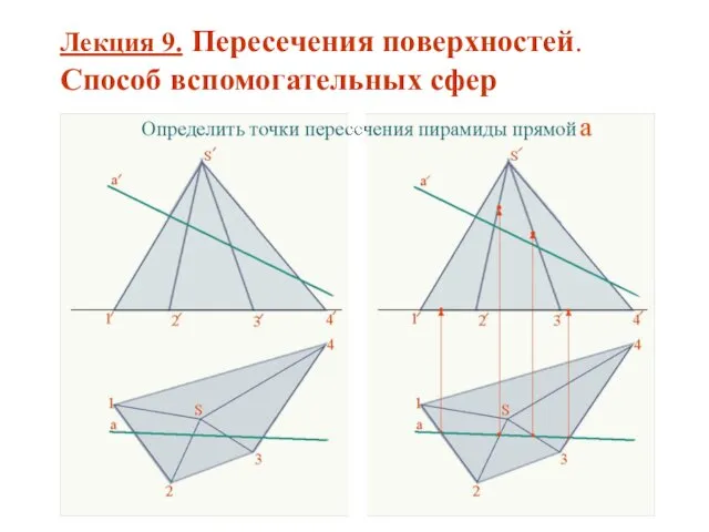 Пересечения поверхностей. Способ вспомогательных сфер. (Лекция 9)
 Атлас педагогических идей
 Слесарное дело. Тест
 Век медный, бронзовый, железный. Презентация к уроку химии 9 класс.