- Shanghai WTL Welding Equipment

Содержание
- 2. Catalogue 1、Introduction of working principle 2、Introduction of main circuit 3、Introduction of control circuit 4、Introduction of panel
- 3. 1、Introduction of working principle
- 4. working principle (MAGIC AC GTIG-200P)
- 5. System chart (MAGIC AC GTIG-200P)
- 6. Explosive drawing
- 7. Component listing
- 9. 2、Introduction of main circuit
- 10. main circuit of Full-bridge Inverter
- 11. Part1:Inorder to pass the EMI test we use an EMC filter interpose between the AC source.
- 12. PFC technology=green power energy P=UI cosφ cosφ=0.99 High power efficiency Global input voltage:95V---270V Avoid input voltage
- 13. PFC chip and theory ICE3PCS03G(see the PDF document) Power input : 95V~270VAC PFC output: 360(working)~385(open circuit)
- 14. PFC theory: Boost
- 15. PFC circuit PFC Inductance FRD IGBT current sense resistor OV protection Brownout protection
- 16. Photo of PFC part U3 PFC IGBT driver U1 PFC control chip
- 17. The location of PFC IGBT
- 18. Preparation of test PFC IGBT 1、We must Switch off the machine 2、After 5 minutes we can
- 19. PFC IGBT Test(A-1) PFC IGBT Test(A-2)
- 20. PFC IGBT Test(A-3) PFC IGBT Test(A-4)
- 21. PFC IGBT Test(A-5) PFC IGBT Test(A-6)
- 22. Solutions when the IGBT is damaged 1、 Check the circuit of PFC IGBT driver may be
- 23. Full-bridge circuit and PWM driver
- 24. Part5: Through the transformer and full-wave rectifier Circuit and full bridge inverter Getting what we want
- 25. The locations of AC IGBT U5 U6 AC Drive Part FRD
- 26. Solutions when the IGBT is damaged 1、 Check the circuit of AC IGBT driver may be
- 27. Part6: Schematic of HF part
- 28. Switch power Part7:the switch power supply +24V and -24V power for the machine Overvoltage protection input
- 29. 110V/220V input test circuit Voltage sampling Control PCB judge
- 30. 3、Introduction of control circuit
- 31. Introduction of control circuit
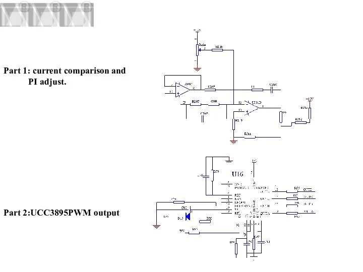
- 32. Part 1: current comparison and PI adjust. Part 2:UCC3895PWM output
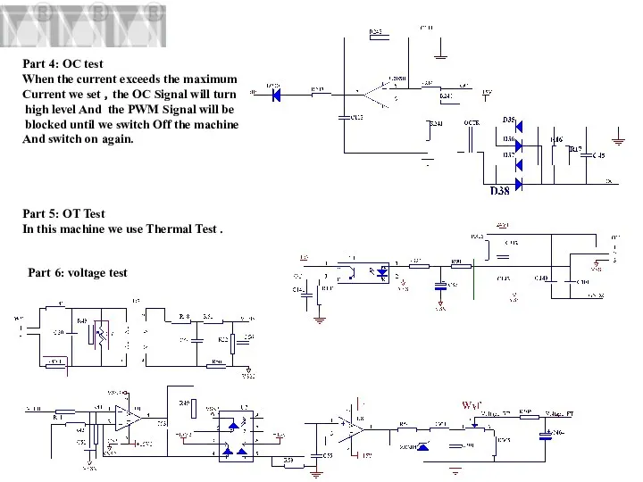
- 33. Part 4: OC test When the current exceeds the maximum Current we set ,the OC Signal
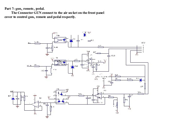
- 34. Part 7: gun、remote、pedal. The Connector GUN connect to the air socket on the front panel cover
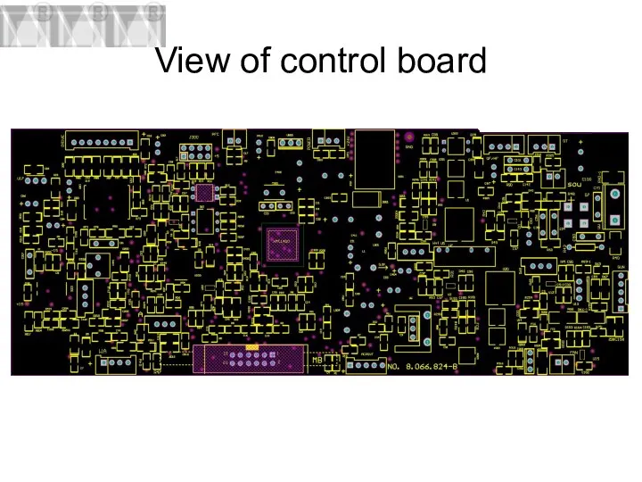
- 35. View of control board
- 36. Photo of control board POWER PFC IFB DRIVER GUN/REMOTE WVIN ACPOUT OT QF/HF FAN MB12 sou
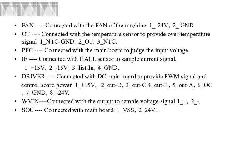
- 37. FAN ---- Connected with the FAN of the machine. 1_-24V,2_ GND OT ---- Connected with the
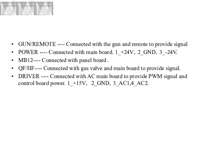
- 38. GUN/REMOTE ---- Connected with the gun and remote to provide signal POWER ---- Connected with main
- 39. 4、Introduction of panel circuit
- 40. Electrical drawing of panel circuit
- 41. panel PCB
- 42. Photo of panel board Current display LED2:Over-temprature or Over-current alarm LED1: power display Process selection PULSE
- 45. 5、Troubleshooting
- 46. A-1:When the machine is turned on , the power LED is not on. Resolution: 1.There is
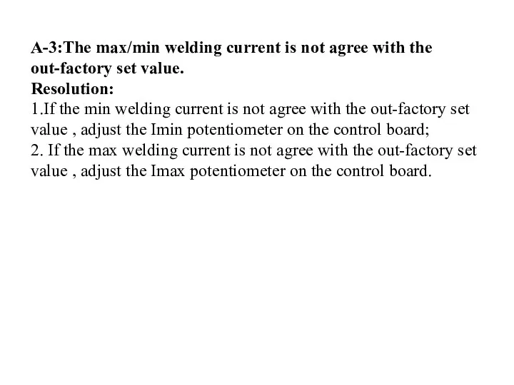
- 47. A-3:The max/min welding current is not agree with the out-factory set value. Resolution: 1.If the min
- 48. A-4:The display welding current is not agree with the actual current. Resolution: 1.The min display welding
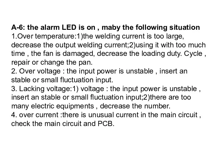
- 49. A-6: the alarm LED is on , maby the following situation 1.Over temperature:1)the welding current is
- 50. B-1:When the machine is turned on , the fan doesn’t work. Resolution: 1.There is something locking
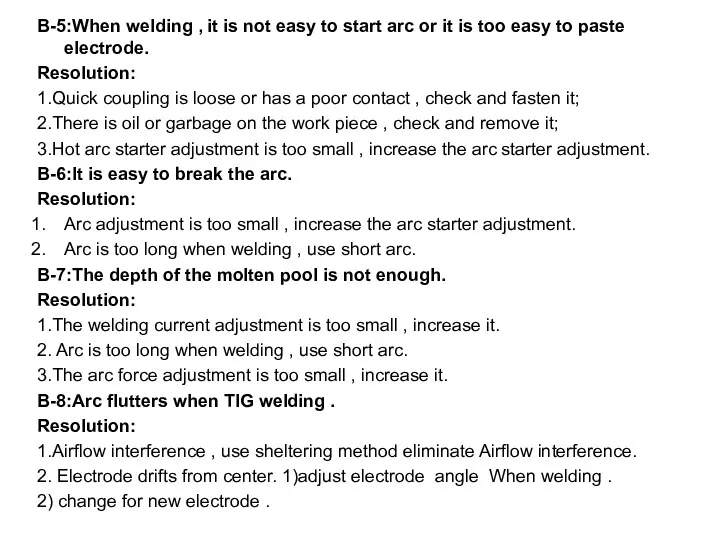
- 51. B-5:When welding , it is not easy to start arc or it is too easy to
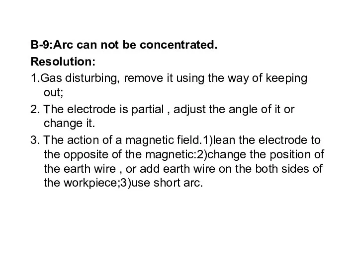
- 52. B-9:Arc can not be concentrated. Resolution: 1.Gas disturbing, remove it using the way of keeping out;
- 53. 6.Component test 1、 UC3895 Test 2、IGBT Test 3、FRD Test
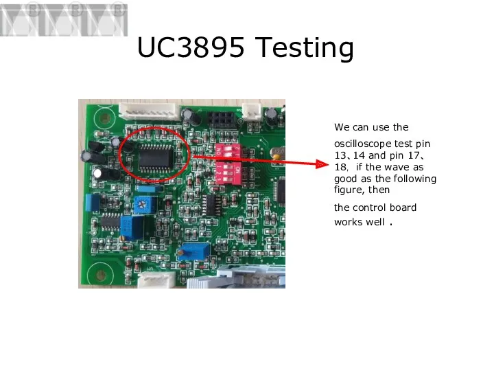
- 54. UC3895 Testing We can use the oscilloscope test pin 13、14 and pin 17、18, if the wave
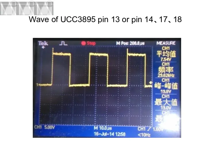
- 55. Wave of UCC3895 pin 13 or pin 14、17、18
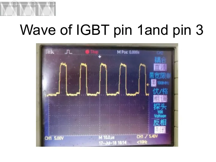
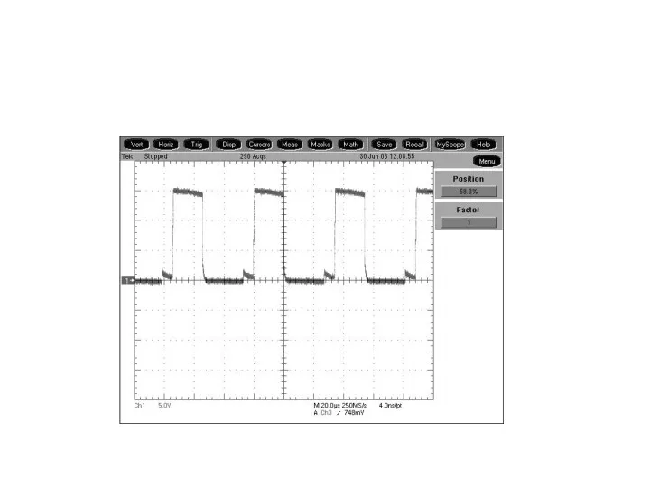
- 56. Wave of IGBT pin 1and pin 3
- 57. The location of IGBT G C E G C E G C E G C E
- 58. Preparation of test IGBT 1、We must Switch off the machine 2、After 5 minutes we can test
- 59. IGBT Test(A-1) IGBT Test(A-2)
- 60. IGBT Test(A-3) IGBT Test(A-4)
- 61. IGBT Test(A-5) IGBT Test(A-6)
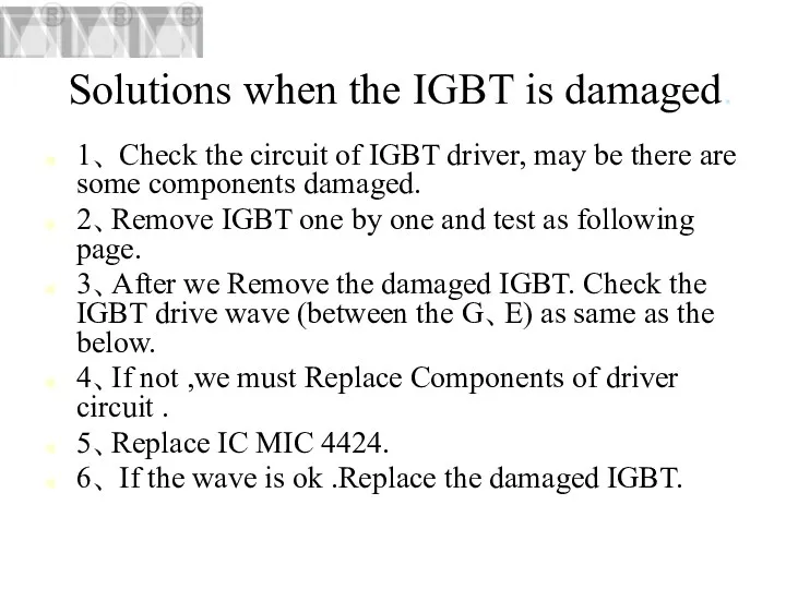
- 62. Solutions when the IGBT is damaged. 1、 Check the circuit of IGBT driver, may be there
- 64. IGBT Test(B-1) IGBT Test(B-2)
- 65. IGBT Test(B-3) IGBT Test(B-4)
- 66. The location of FRD
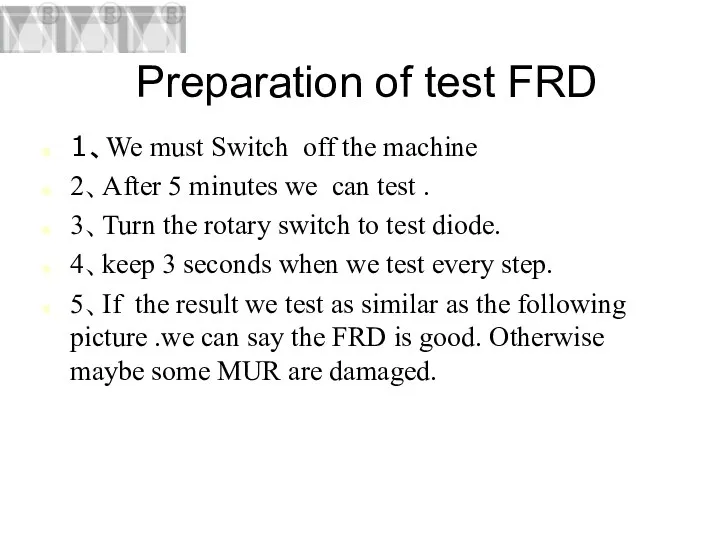
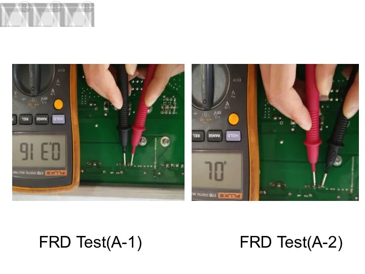
- 67. Preparation of test FRD 1、We must Switch off the machine 2、After 5 minutes we can test
- 68. FRD Test(A-1) FRD Test(A-2)
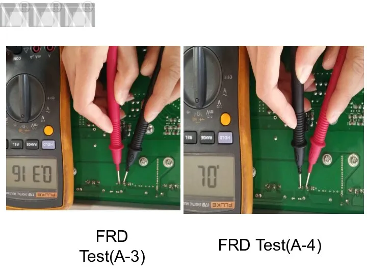
- 69. FRD Test(A-3) FRD Test(A-4)
- 70. Solutions when the FRD is damaged 1、 Remove FRD one by one and test as following
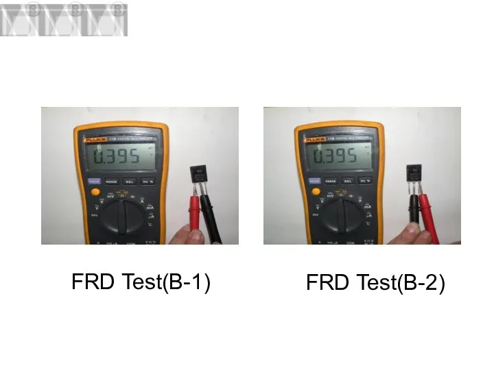
- 71. FRD Test(B-1) FRD Test(B-2)
- 72. FRD Test(B-3) FRD Test(B-4) FRD Test(B-3)
- 73. Q & A
- 75. Скачать презентацию
Catalogue
1、Introduction of working principle
2、Introduction of main circuit
3、Introduction of control circuit
4、Introduction of
Catalogue
1、Introduction of working principle
2、Introduction of main circuit
3、Introduction of control circuit
4、Introduction of

1、Introduction of working principle
1、Introduction of working principle
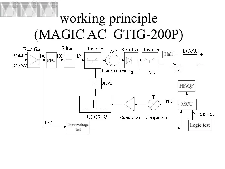
working principle
(MAGIC AC GTIG-200P)
working principle
(MAGIC AC GTIG-200P)
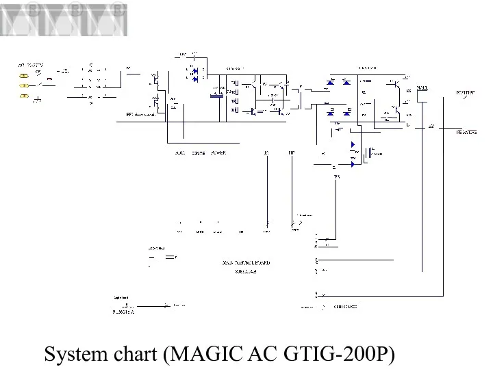
System chart (MAGIC AC GTIG-200P)
System chart (MAGIC AC GTIG-200P)
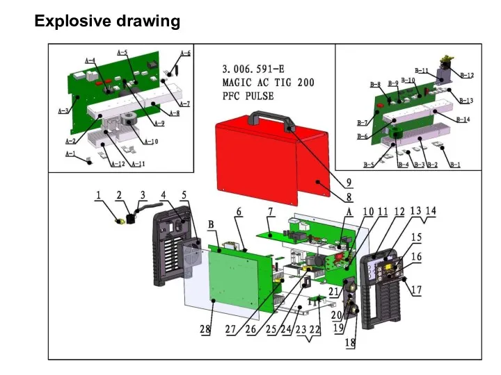
Explosive drawing
Explosive drawing
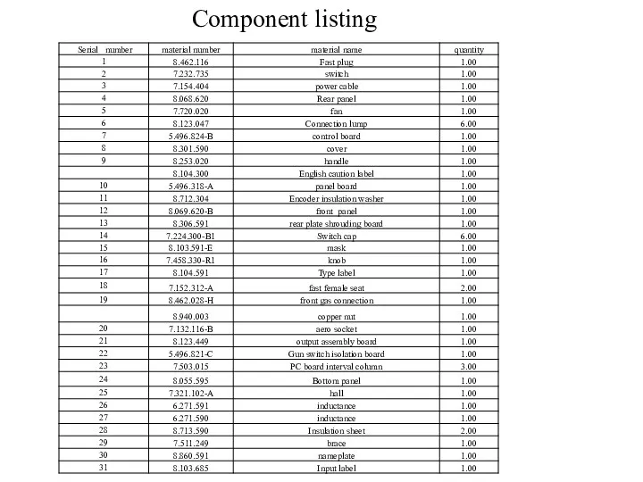
Component listing
Component listing


2、Introduction of main circuit
2、Introduction of main circuit
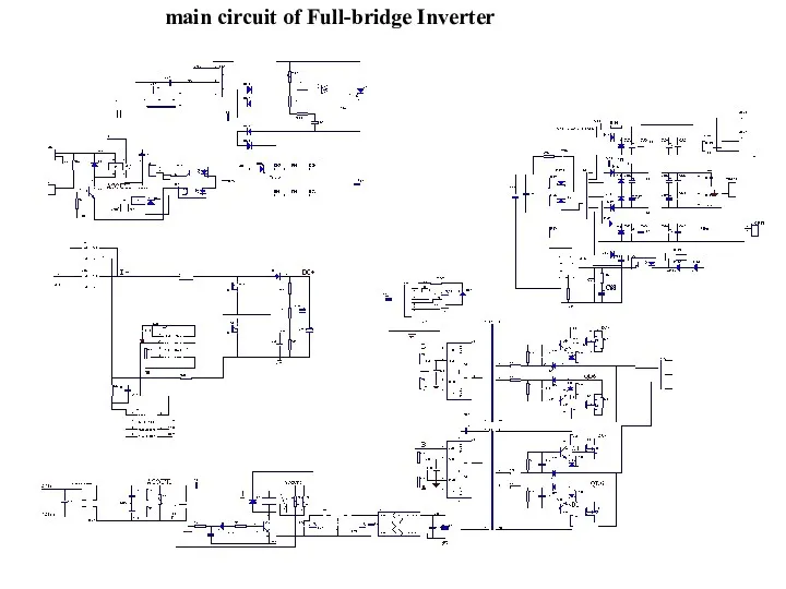
main circuit of Full-bridge Inverter
main circuit of Full-bridge Inverter

Part1:Inorder to pass the
EMI test we use an
EMC filter
Part1:Inorder to pass the
EMI test we use an
EMC filter

PFC technology=green power energy
P=UI cosφ
cosφ=0.99
High power efficiency
Global input
PFC technology=green power energy
P=UI cosφ
cosφ=0.99
High power efficiency
Global input
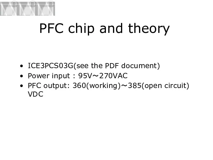
PFC chip and theory
ICE3PCS03G(see the PDF document)
Power input : 95V~270VAC
PFC output:
PFC chip and theory
ICE3PCS03G(see the PDF document)
Power input : 95V~270VAC
PFC output:
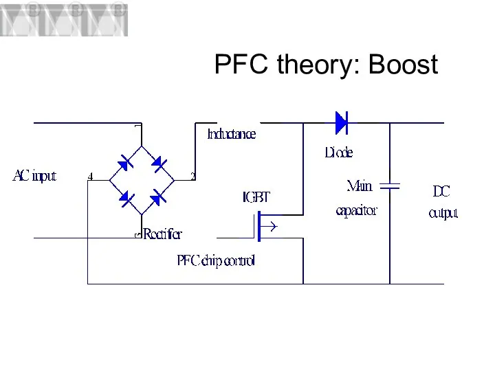
PFC theory: Boost
PFC theory: Boost
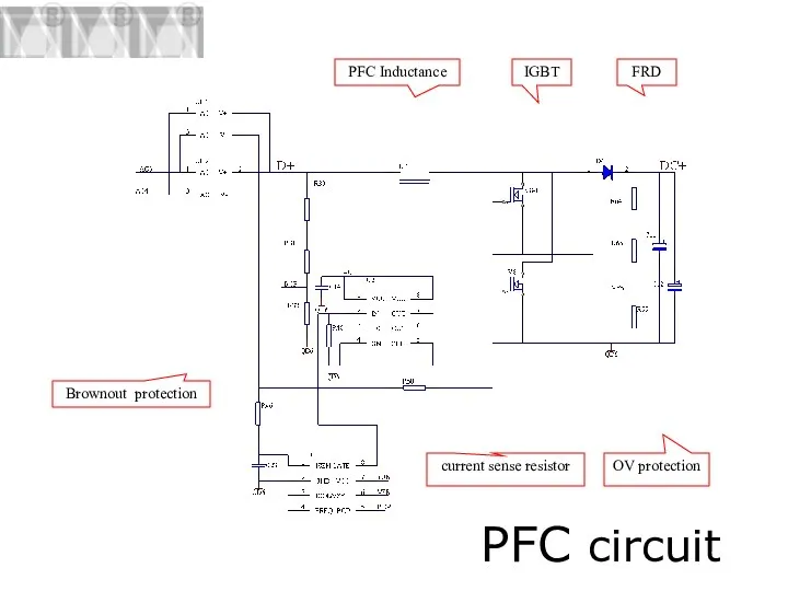
PFC circuit
PFC Inductance
FRD
IGBT
current sense resistor
OV protection
Brownout protection
PFC circuit
PFC Inductance
FRD
IGBT
current sense resistor
OV protection
Brownout protection
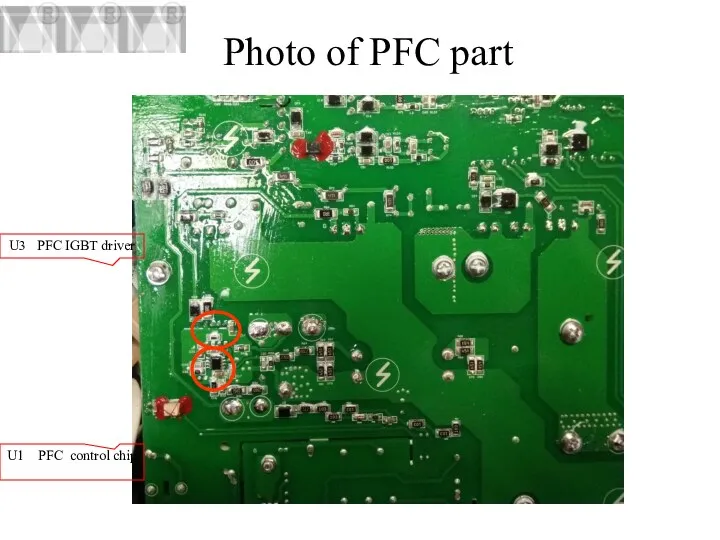
Photo of PFC part
U3 PFC IGBT driver
U1 PFC control chip
Photo of PFC part
U3 PFC IGBT driver
U1 PFC control chip
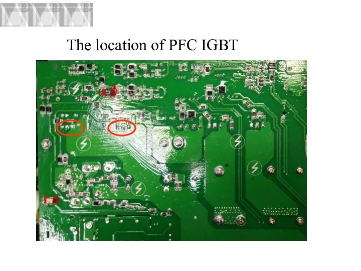
The location of PFC IGBT
The location of PFC IGBT
Preparation of test PFC IGBT
1、We must Switch off the machine
2、After
Preparation of test PFC IGBT
1、We must Switch off the machine
2、After
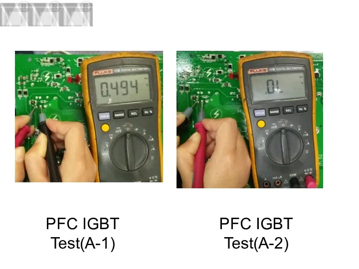
PFC IGBT Test(A-1)
PFC IGBT Test(A-2)
PFC IGBT Test(A-1)
PFC IGBT Test(A-2)
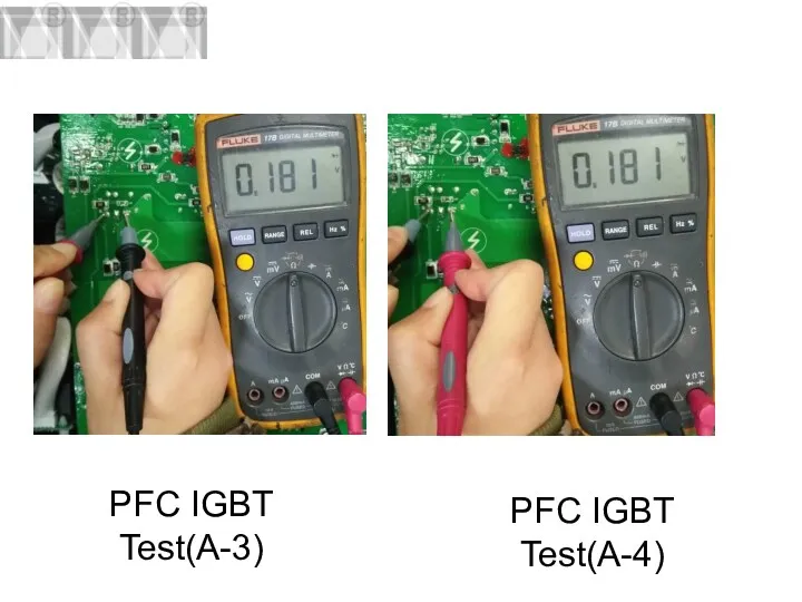
PFC IGBT Test(A-3)
PFC IGBT Test(A-4)
PFC IGBT Test(A-3)
PFC IGBT Test(A-4)
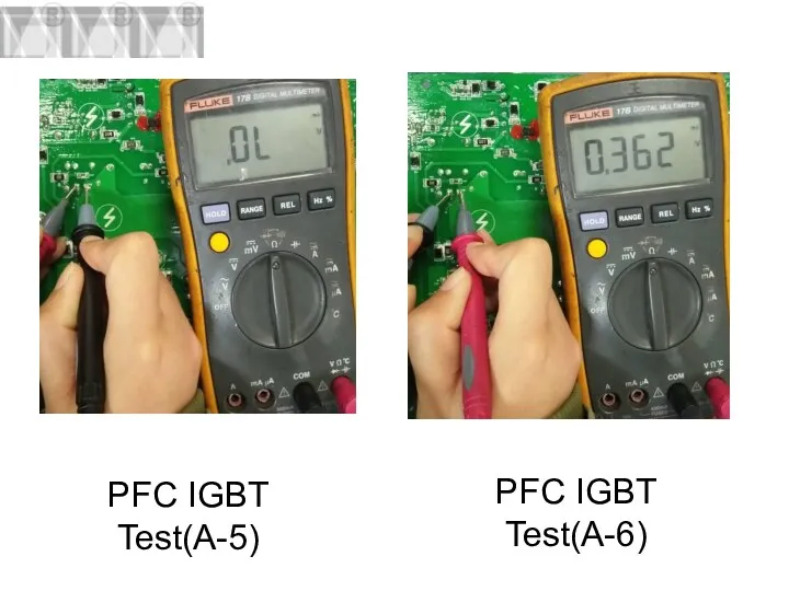
PFC IGBT Test(A-5)
PFC IGBT Test(A-6)
PFC IGBT Test(A-5)
PFC IGBT Test(A-6)
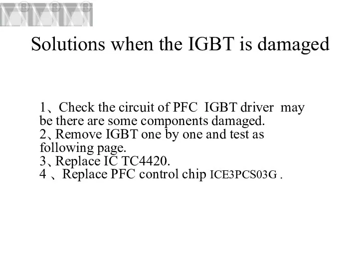
Solutions when the IGBT is damaged
1、 Check the circuit of PFC
Solutions when the IGBT is damaged
1、 Check the circuit of PFC
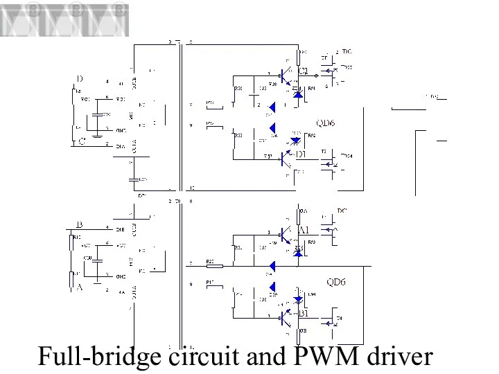
Full-bridge circuit and PWM driver
Full-bridge circuit and PWM driver

Part5: Through the transformer and full-wave rectifier Circuit and full bridge
Part5: Through the transformer and full-wave rectifier Circuit and full bridge
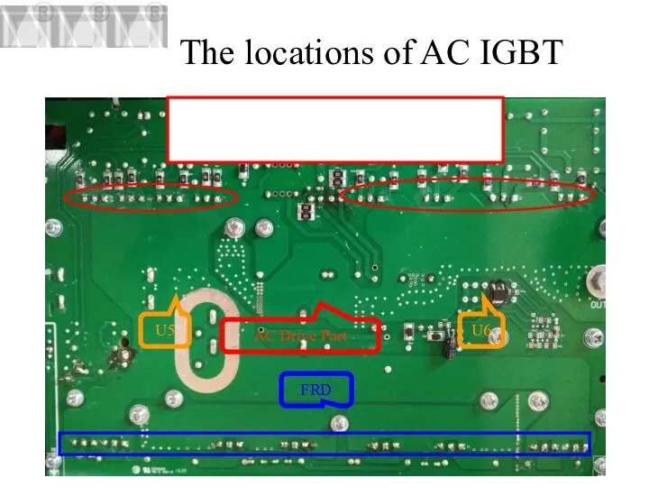
The locations of AC IGBT
U5
U6
AC Drive Part
FRD
The locations of AC IGBT
U5
U6
AC Drive Part
FRD
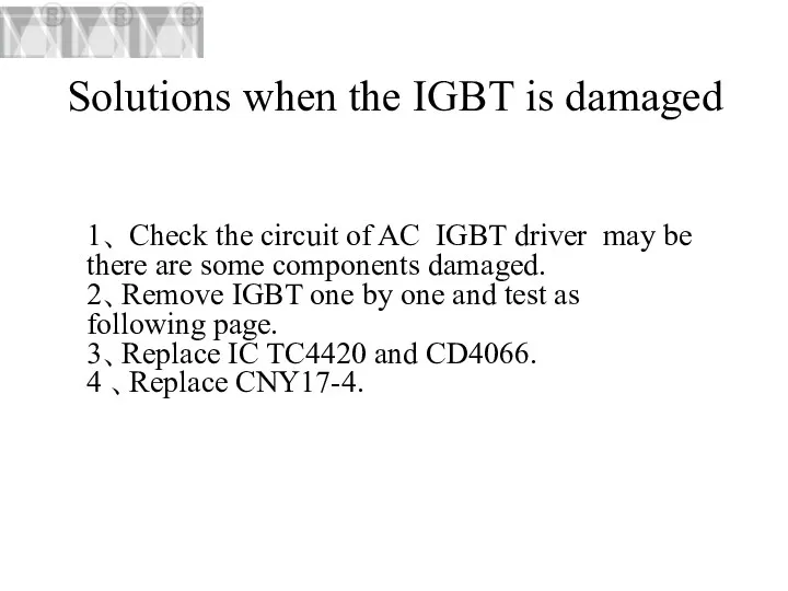
Solutions when the IGBT is damaged
1、 Check the circuit of AC
Solutions when the IGBT is damaged
1、 Check the circuit of AC
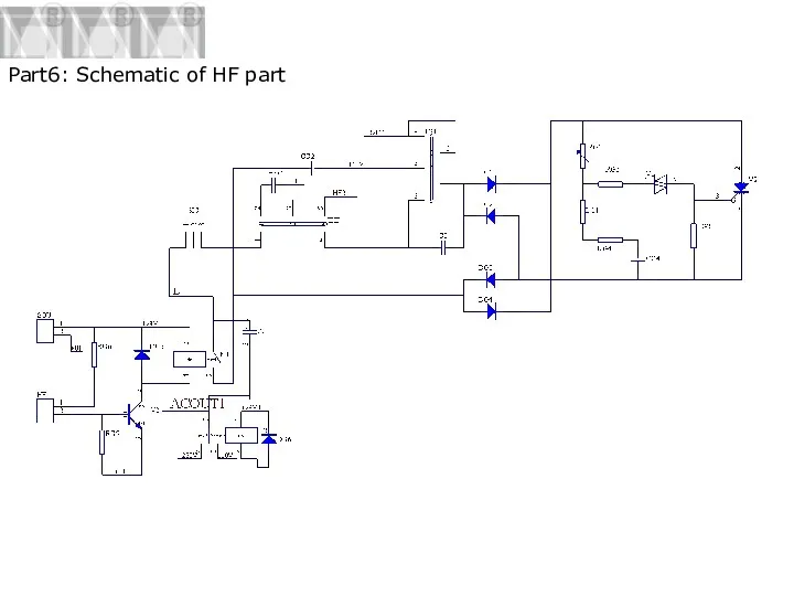
Part6: Schematic of HF part
Part6: Schematic of HF part
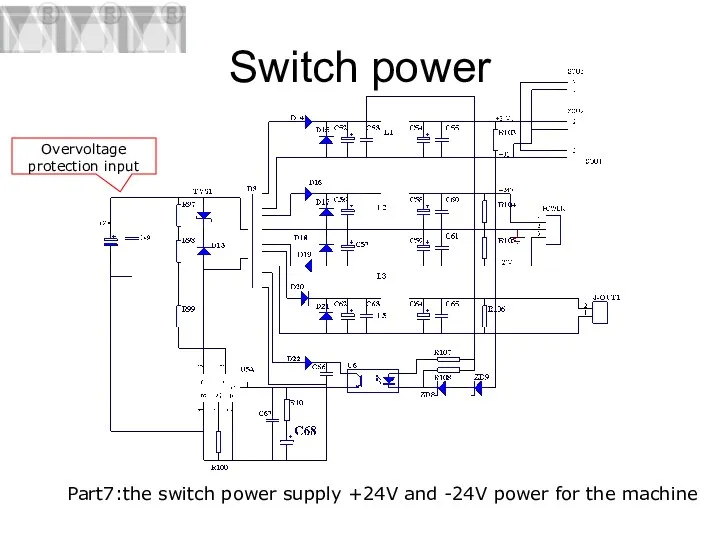
Switch power
Part7:the switch power supply +24V and -24V power for
Switch power
Part7:the switch power supply +24V and -24V power for
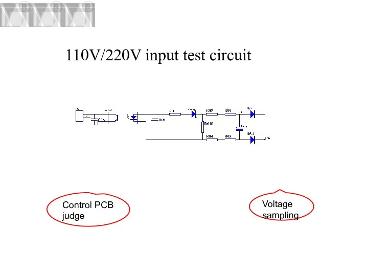
110V/220V input test circuit
Voltage
sampling
Control PCB judge
110V/220V input test circuit
Voltage
sampling
Control PCB judge
3、Introduction of control circuit
3、Introduction of control circuit
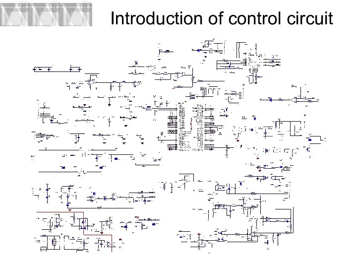
Introduction of control circuit
Introduction of control circuit
Part 1: current comparison and
PI adjust.
Part 2:UCC3895PWM output
Part 1: current comparison and
PI adjust.
Part 2:UCC3895PWM output
Part 4: OC test
When the current exceeds the maximum
Current
Part 4: OC test
When the current exceeds the maximum
Current
Part 7: gun、remote、pedal.
The Connector GUN connect to the air socket
Part 7: gun、remote、pedal.
The Connector GUN connect to the air socket
View of control board
View of control board

Photo of control board
POWER
PFC
IFB
DRIVER
GUN/REMOTE
WVIN
ACPOUT
OT
QF/HF
FAN
MB12
sou
Photo of control board
POWER
PFC
IFB
DRIVER
GUN/REMOTE
WVIN
ACPOUT
OT
QF/HF
FAN
MB12
sou
FAN ---- Connected with the FAN of the machine. 1_-24V,2_ GND
OT
FAN ---- Connected with the FAN of the machine. 1_-24V,2_ GND
OT
GUN/REMOTE ---- Connected with the gun and remote to provide signal
POWER
GUN/REMOTE ---- Connected with the gun and remote to provide signal
POWER
4、Introduction of panel circuit
4、Introduction of panel circuit
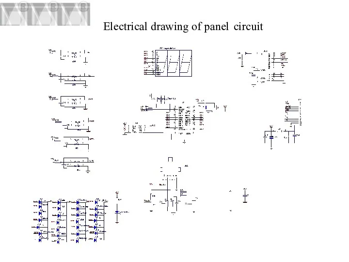
Electrical drawing of panel circuit
Electrical drawing of panel circuit
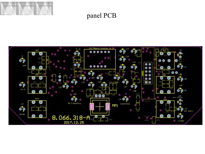
panel PCB
panel PCB
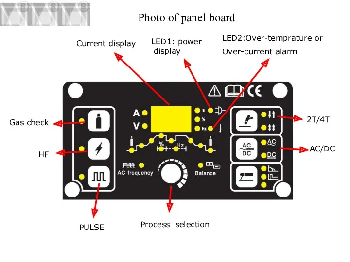
Photo of panel board
Current display
LED2:Over-temprature or
Over-current alarm
LED1: power display
Process
Photo of panel board
Current display
LED2:Over-temprature or
Over-current alarm
LED1: power display
Process
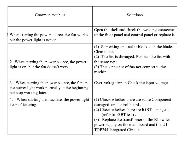
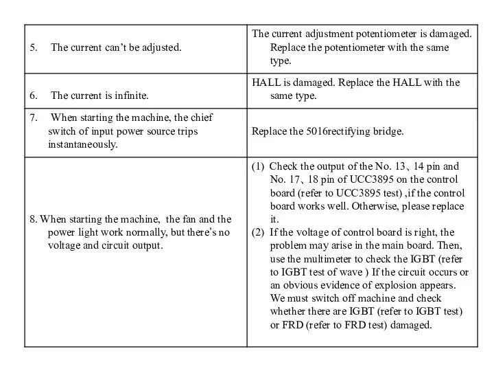

5、Troubleshooting
5、Troubleshooting

A-1:When the machine is turned on , the power LED is
A-1:When the machine is turned on , the power LED is
A-3:The max/min welding current is not agree with the out-factory set
A-3:The max/min welding current is not agree with the out-factory set

A-4:The display welding current is not agree with the actual current.
Resolution:
1.The
A-4:The display welding current is not agree with the actual current. Resolution: 1.The
A-6: the alarm LED is on , maby the following situation
A-6: the alarm LED is on , maby the following situation

B-1:When the machine is turned on , the fan doesn’t work.
Resolution:
1.There
B-1:When the machine is turned on , the fan doesn’t work.
Resolution:
1.There
B-5:When welding , it is not easy to start arc or
B-5:When welding , it is not easy to start arc or
B-9:Arc can not be concentrated.
Resolution:
1.Gas disturbing, remove it using the way
B-9:Arc can not be concentrated.
Resolution:
1.Gas disturbing, remove it using the way
6.Component test
1、 UC3895 Test
2、IGBT Test
3、FRD Test
6.Component test
1、 UC3895 Test
2、IGBT Test
3、FRD Test
UC3895 Testing
We can use the
oscilloscope test pin 13、14 and pin 17、18,
UC3895 Testing
We can use the
oscilloscope test pin 13、14 and pin 17、18,
Wave of UCC3895 pin 13 or pin 14、17、18
Wave of UCC3895 pin 13 or pin 14、17、18
Wave of IGBT pin 1and pin 3
Wave of IGBT pin 1and pin 3
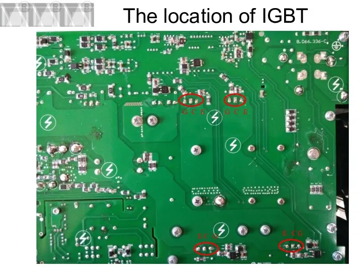
The location of IGBT
G
C
E
G
C
E
G
C
E
G
C
E
The location of IGBT
G
C
E
G
C
E
G
C
E
G
C
E

Preparation of test IGBT
1、We must Switch off the machine
2、After 5
Preparation of test IGBT
1、We must Switch off the machine
2、After 5
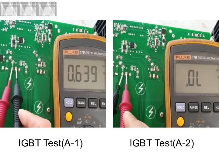
IGBT Test(A-1)
IGBT Test(A-2)
IGBT Test(A-1)
IGBT Test(A-2)
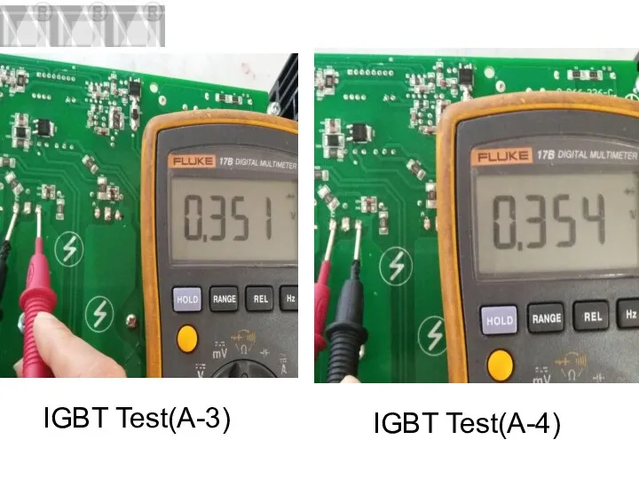
IGBT Test(A-3)
IGBT Test(A-4)
IGBT Test(A-3)
IGBT Test(A-4)
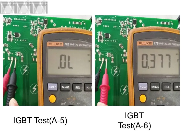
IGBT Test(A-5)
IGBT Test(A-6)
IGBT Test(A-5)
IGBT Test(A-6)
Solutions when the IGBT is damaged.
1、 Check the circuit of IGBT
Solutions when the IGBT is damaged.
1、 Check the circuit of IGBT
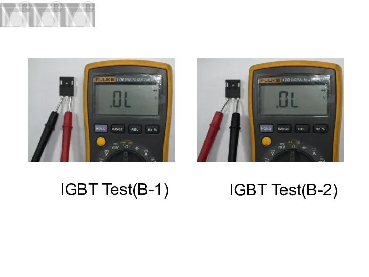
IGBT Test(B-1)
IGBT Test(B-2)
IGBT Test(B-1)
IGBT Test(B-2)

IGBT Test(B-3)
IGBT Test(B-4)
IGBT Test(B-3)
IGBT Test(B-4)
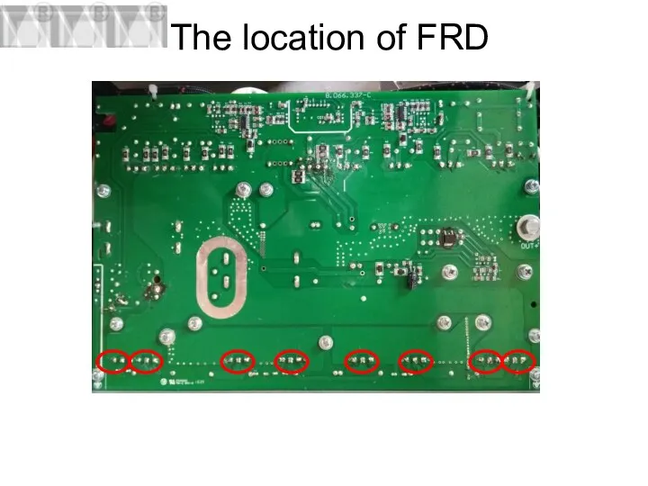
The location of FRD
The location of FRD
Preparation of test FRD
1、We must Switch off the machine
2、After 5
Preparation of test FRD
1、We must Switch off the machine
2、After 5
FRD Test(A-1)
FRD Test(A-2)
FRD Test(A-1)
FRD Test(A-2)
FRD Test(A-3)
FRD Test(A-4)
FRD Test(A-3)
FRD Test(A-4)
Solutions when the FRD is damaged
1、 Remove FRD one by one
Solutions when the FRD is damaged
1、 Remove FRD one by one
FRD Test(B-1)
FRD Test(B-2)
FRD Test(B-1)
FRD Test(B-2)

FRD Test(B-3)
FRD Test(B-4)
FRD Test(B-3)
FRD Test(B-3)
FRD Test(B-4)
FRD Test(B-3)

Q & A
Q & A
 презентация к уроку географии Западная Европа.
 Лучшие фотографии вторая половина 20 века
 Организационные основы гражданской обороны, нормативное правовое регулирование в области гражданской обороны
 Буква Г
 Работа с отзывами гостей гостиницы
 Використання ультразвуку в медецині
 Возбуждение и рассмотрение дела об административном правонарушении
 Роль религии в жизни общества
 Умный дом. Что же такое умный дом?
 Промышленный маркетинг в металлургической отрасли. Стратегический маркетинг и стратегическое позиционирование предприятий
 Обследование зданий и сооружений. Сбор и анализ технической документации при обследовании (лекция 3, продолжение)
 ПрезентацияЛегун
 Формирование территории России
 Ель (лат.Picea)
 Легенды села Чибирлей и села 2-е Тарлаково Кузнецкого района
 Фовизм
 Электронные библиотеки. За и против
 Биржевые кризисы
 Present Simple Present Continuous
 МУРАЛЫ И ГРАФФИТИ КАК ЭЛЕМЕНТ НАСКАЛЬНОЙ ЖИВОПИСИ
 Дисперсные системы: общая характеристика и классификация
 Выпуклость функции. Точки перегиба
 Презентация о подготовке к экзаменам
 УГЛЕВОДОРОДЫ
 Правила эксплуатации путевого инструмента
 Совершенствование организации складской логистической системы компании ООО БестОйл
 Инструкция для водителей перевозчиков в топливном проекте
 Презентация: Вернуть бы маму на мгновенье