- SKIF injector complex

Содержание
- 2. Main injector parameters E = 3 GeV I = 400 mA εX = 90 pm*rad C
- 3. Main parameters of the LINAC Main linac parameters User modes of the SKIF storage ring
- 4. Scheme of the linear accelerator with energy of 200 MeV
- 5. RF gun with frequency of 178 MHz Cathode is based on the RF triode GS-34
- 6. Field distribution along the axis of the cavity Simulation of the emission beam by code ASTRA
- 7. Bunching cavity with frequency of 535 MHz (the third harmonic)
- 8. Buncher-preaccelerator and regular accelerating structure Beam energy of 42 MeV with RF power of 25 MW
- 9. Beam dynamics simulation Beam size in bunching system Beam size in regular structure Output beam parameters
- 10. The booster lattice consists of four super periods. The horizontal emittance at 3 GeV is 37.4
- 11. Booster lattice Super period consists of 5 cells with two modified cells at the edges to
- 12. Main parameters of the booster magnets Booster magnets
- 13. LINAC to Booster transfer line 2 dipoles with rotation angle 230 mrad, 2 dipoles with rotation
- 14. Booster Injection 4.5 m Kicker’s current form Injection kicker Injection septum magnet
- 15. Booster extraction scheme. 1- equilibrium orbit, 2- orbit before extraction, 3- extracted beam. Booster Extraction Booster
- 16. Booster to Storage ring transfer line 1 horizontal dipole with rotation angle 161 mrad, 2 vertical
- 17. Injection to Storage Ring 2D model of the Lembertson’s septum-magnet Magnetic fields in aperture (Hin =
- 18. Estimates of injection The usual mode is injection train of bunches up to 300 nsec long
- 20. Скачать презентацию
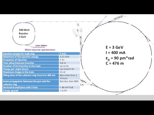
Main injector parameters
E = 3 GeV
I = 400 mA
εX = 90
Main injector parameters
E = 3 GeV
I = 400 mA
εX = 90
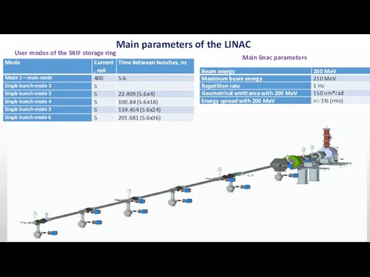
Main parameters of the LINAC
Main linac parameters
User modes of the SKIF
Main parameters of the LINAC
Main linac parameters
User modes of the SKIF
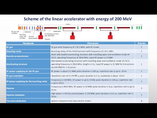
Scheme of the linear accelerator with energy of 200 MeV
Scheme of the linear accelerator with energy of 200 MeV
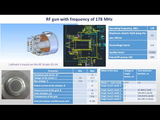
RF gun with frequency of 178 MHz
Cathode is based on the
RF gun with frequency of 178 MHz
Cathode is based on the
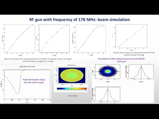
Field distribution along the axis of the cavity
Simulation of the emission
Field distribution along the axis of the cavity
Simulation of the emission
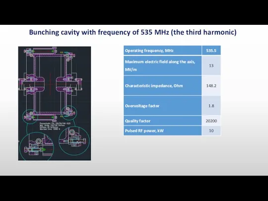
Bunching cavity with frequency of 535 MHz (the third harmonic)
Bunching cavity with frequency of 535 MHz (the third harmonic)
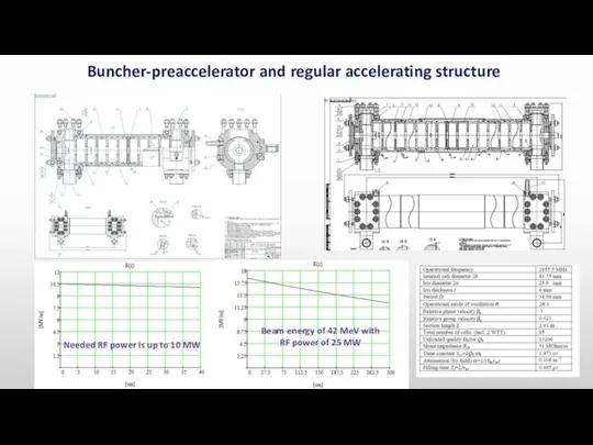
Buncher-preaccelerator and regular accelerating structure
Beam energy of 42 MeV with RF
Buncher-preaccelerator and regular accelerating structure
Beam energy of 42 MeV with RF
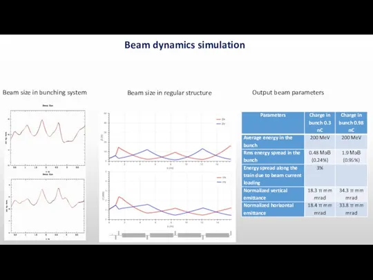
Beam dynamics simulation
Beam size in bunching system
Beam size in regular structure
Output
Beam dynamics simulation
Beam size in bunching system
Beam size in regular structure
Output
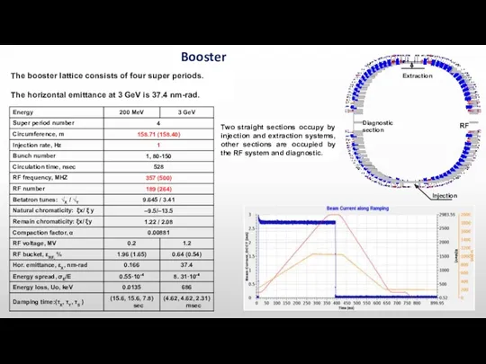
The booster lattice consists of four super periods.
The horizontal emittance at
The booster lattice consists of four super periods.
The horizontal emittance at
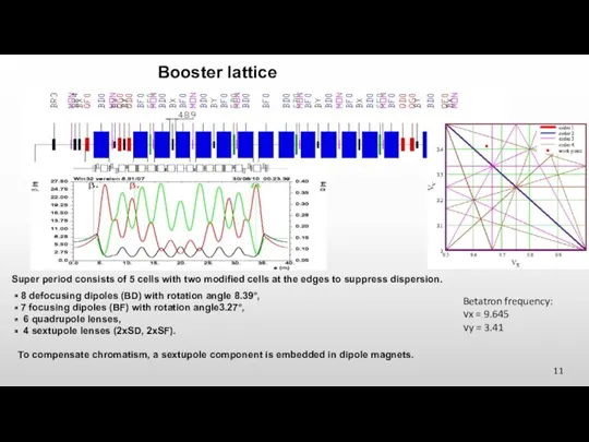
Booster lattice
Super period consists of 5 cells with two modified cells
Booster lattice
Super period consists of 5 cells with two modified cells
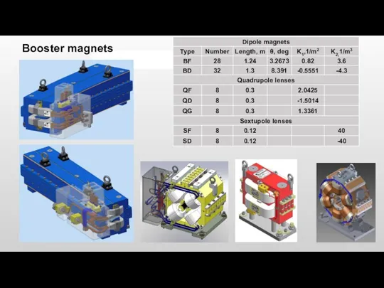
Main parameters of the booster magnets
Booster magnets
Main parameters of the booster magnets
Booster magnets
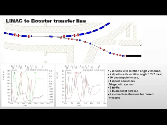
LINAC to Booster transfer line
2 dipoles with rotation angle 230
LINAC to Booster transfer line
2 dipoles with rotation angle 230
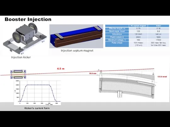
Booster Injection
4.5 m
Kicker’s current form
Injection kicker
Injection septum magnet
Booster Injection
4.5 m
Kicker’s current form
Injection kicker
Injection septum magnet
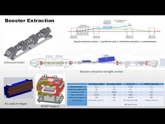
Booster extraction scheme. 1- equilibrium orbit, 2- orbit before extraction, 3-
Booster extraction scheme. 1- equilibrium orbit, 2- orbit before extraction, 3-
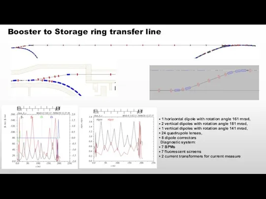
Booster to Storage ring transfer line
1 horizontal dipole with rotation
Booster to Storage ring transfer line
1 horizontal dipole with rotation
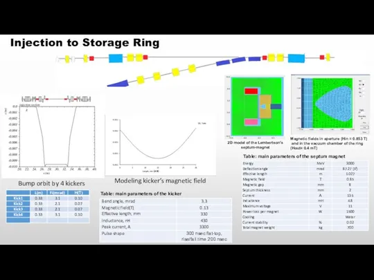
Injection to Storage Ring
2D model of the Lembertson’s septum-magnet
Magnetic fields in
Injection to Storage Ring
2D model of the Lembertson’s septum-magnet
Magnetic fields in
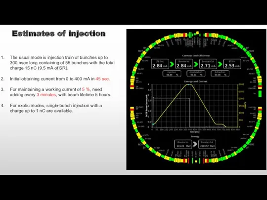
Estimates of injection
The usual mode is injection train of bunches up
Estimates of injection
The usual mode is injection train of bunches up
 Любимые места моего района
 Тренажер. Задание 20 ЕГЭ по русскому языку
 Русский модерн
 Нейровизуализационные методы диагностики заболевании нервной системы
 Фотоматериалы к проекту Путешествие по Золотому кольцу России Диск
 Рекомендации по работе с родителями
 Характеристика, руководство, сопровождение сюжетно-ролевых игр
 История возникновения проблемы фирменного стиля
 ИТ в сфере управления
 ЕГЭ по русскому языку: выполнение тестовых заданий
 Субсидии на газификацию
 Методика профессионального обучения
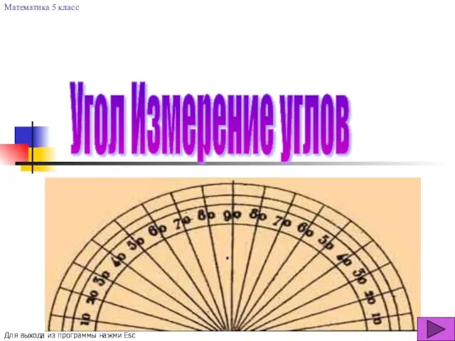 Угол. Измерение углов
 акция засветись
 Childhood Education and References for Sustainable Education
 Tattoo_salon
 Джанни Родари, сказка Приключения Чиполлино
 Твой бюджет. Благоустройство детской площадки. Пулковский парк в Московском районе
 презентация Готовимся к школе
 Программа поэтапной работы над проектом
 Мистецьке життя краю Тернопільщини
 Родительское собрание в 1 классе
 Игра Большая игра, посвященная юбилею пионерии.
 Комбинационные логические устройства. Арифметико-логические устройства (АЛУ). Лекция 4
 Плотность нефти и нефтепродуктов
 Автоматизация процесса пропарки и пропитки древесной щепы в производстве ХТММ
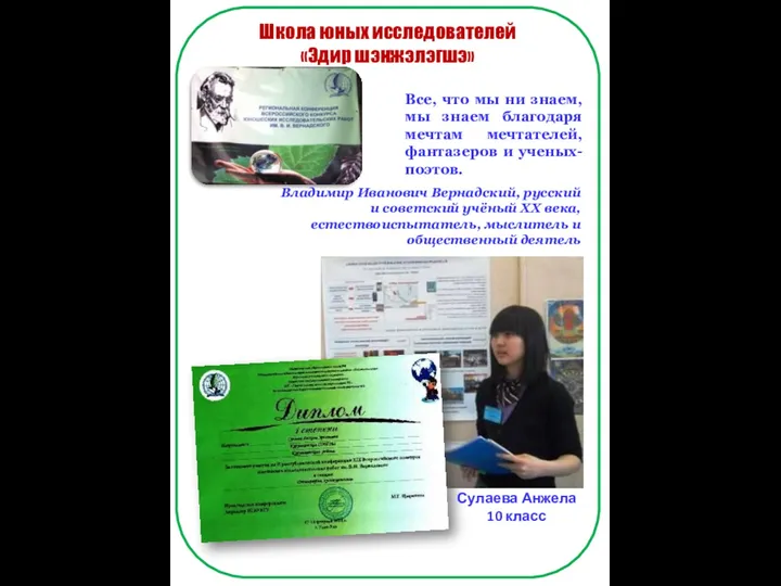 Выставка исследовательская деятельность
 Праздник Ильин день