- STP Specific Training Packages. Sakhalin Energy LNG/OET/TLU

Содержание
- 2. Sakhalin Energy LNG/OET/TLU S T P Unit 6200
- 3. Process Introduction Purpose of the Unit Process description Equipment Health, Safety and Environment Routine checks The
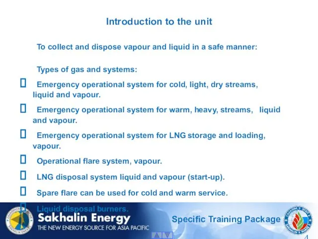
- 4. Introduction to the unit To collect and dispose vapour and liquid in a safe manner: Types
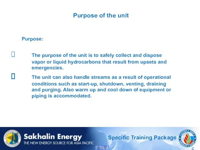
- 5. Purpose of the unit Purpose: The purpose of the unit is to safely collect and dispose
- 6. Unit 6400 position on the Plant overview 6200
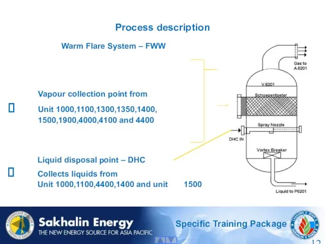
- 7. Process description Warm Flare System (FWW) All the warm vapours are collected into a single 48”
- 8. Process description Warm Liquid Disposal System (DHC) The warm liquids from manual drains are collected in
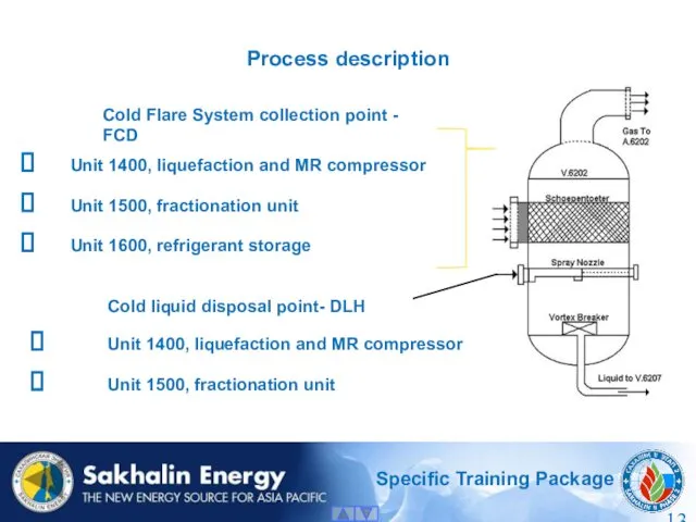
- 9. Process description Cold Flare System (FCD) Cold dry and light hydrocarbon vapours from unit 1400, 1500
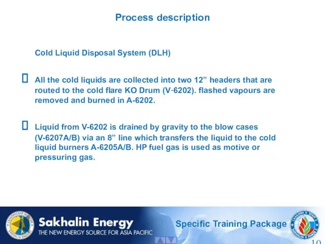
- 10. Process description Cold Liquid Disposal System (DLH) All the cold liquids are collected into two 12”
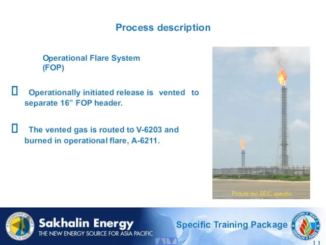
- 11. Process description Operationally initiated release is vented to separate 16” FOP header. The vented gas is
- 12. Process description Liquid disposal point – DHC Collects liquids from Unit 1000,1100,4400,1400 and unit 1500 Warm
- 13. Process description Cold liquid disposal point- DLH Unit 1400, liquefaction and MR compressor Unit 1500, fractionation
- 14. LNG Storage and Loading Flare – FLP Unit 3400, LNG storage and loading Boil-off gas compressors
- 15. Fuel Gas: High pressure fuel gas is used for: Motive gas in the blow cases V-6207A/B.
- 16. Blow case: Liquid from the cold flare KO drums is drained by gravity to one of
- 17. Flare Overview
- 18. Major equipment 3 flare KO drums One blow case (two vessels) Two warm liquid disposal pumps
- 19. Health, Safety and Environment Health, Safety: Noise when the flare is operating. Radiated heat from the
- 20. Environment Controlled releases to atmosphere from the flares and liquid disposal burners pose no harm to
- 22. Скачать презентацию
Sakhalin Energy LNG/OET/TLU
S T P
Unit 6200
Sakhalin Energy LNG/OET/TLU
S T P
Unit 6200
Process Introduction
Purpose of the Unit
Process description
Equipment
Health, Safety and Environment
Routine checks
The
Process Introduction
Purpose of the Unit
Process description
Equipment
Health, Safety and Environment
Routine checks
The
Introduction to the unit
To collect and dispose vapour and liquid in
Introduction to the unit
To collect and dispose vapour and liquid in
Purpose of the unit
Purpose:
The purpose of the unit is to
Purpose of the unit
Purpose:
The purpose of the unit is to
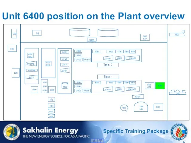
Unit 6400 position on the Plant overview
6200
Unit 6400 position on the Plant overview
6200
Process description
Warm Flare System (FWW)
All the warm vapours are collected
Process description
Warm Flare System (FWW)
All the warm vapours are collected
Process description
Warm Liquid Disposal System (DHC)
The warm liquids from manual
Process description
Warm Liquid Disposal System (DHC)
The warm liquids from manual
Process description
Cold Flare System (FCD)
Cold dry and light hydrocarbon vapours from
Process description
Cold Flare System (FCD)
Cold dry and light hydrocarbon vapours from
Process description
Cold Liquid Disposal System (DLH)
All the cold liquids are
Process description
Cold Liquid Disposal System (DLH)
All the cold liquids are
Process description
Operationally initiated release is vented to separate 16” FOP header.
Process description
Operationally initiated release is vented to separate 16” FOP header.
Process description
Liquid disposal point – DHC
Collects liquids from
Unit 1000,1100,4400,1400 and
Process description
Liquid disposal point – DHC
Collects liquids from
Unit 1000,1100,4400,1400 and
Process description
Cold liquid disposal point- DLH
Unit 1400, liquefaction and MR
Process description
Cold liquid disposal point- DLH
Unit 1400, liquefaction and MR
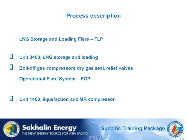
LNG Storage and Loading Flare – FLP
Unit 3400, LNG storage and
LNG Storage and Loading Flare – FLP
Unit 3400, LNG storage and
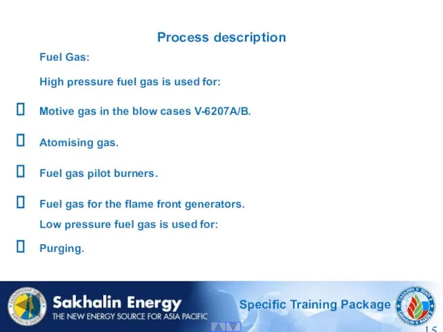
Fuel Gas:
High pressure fuel gas is used for:
Motive gas in
Fuel Gas:
High pressure fuel gas is used for:
Motive gas in
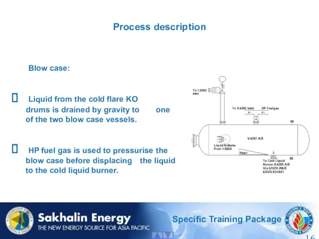
Blow case:
Liquid from the cold flare KO drums is drained by
Liquid from the cold flare KO drums is drained by
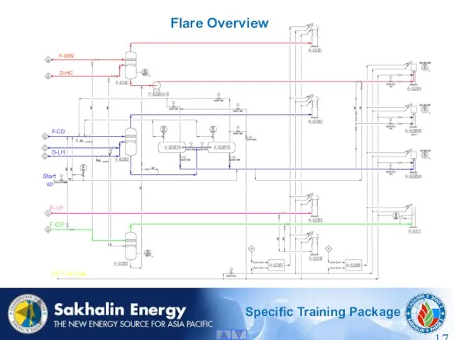
Flare Overview
Flare Overview
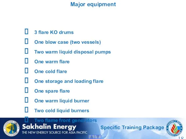
Major equipment
3 flare KO drums
One blow case (two vessels)
Two warm liquid
Major equipment
3 flare KO drums
One blow case (two vessels)
Two warm liquid
Health, Safety and Environment
Health, Safety:
Noise when the flare is operating.
Radiated heat
Health, Safety and Environment
Health, Safety:
Noise when the flare is operating.
Radiated heat
Environment
Controlled releases to atmosphere from the flares and liquid disposal
Environment
Controlled releases to atmosphere from the flares and liquid disposal
 ПРЕЗЕНТАЦИЯ: РАЗВИТИЕ ИГРОВОЙ ДЕЯТЕЛЬНОСТИ ДЕТЕЙ ДОШКОЛЬНОГО ВОЗРАСТА
 Строение периферического отдела скелета животных
 Описание климата по климатограммам
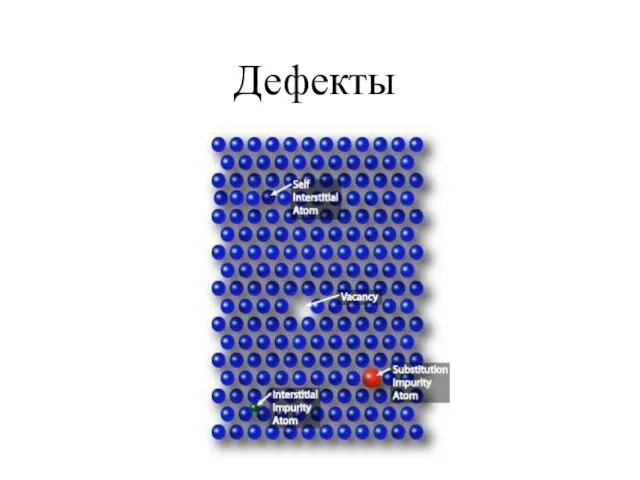 Кристаллизация Осмия. Дефекты. Поликристаллы
 Обструктивные уропатии
 Строение атома
 12 ИЮНЯ ДЕНЬ РОССИИ
 Предмет и метод экономической теории
 Урок естествознания 10 класс Традиции и революции в естествознании. Религиозная традиция
 Школы менеджмента
 Взаимодействие с родителями в процессе обучения ребёнка мелкой моторики.
 Классификация инноваций
 Минералы Урала
 презентация Реакции обмена
 Атмосфера. Ветер
 Презентация Фосфор
 Электропитание и электроснабжение нетяговых потребителей
 Презентация Трудности адаптации ребенка в 5 классе
 Северная война 1700-1721
 Разработка мобильных приложений на 1С и организация взаимодействия через Интернет
 Второстепенные члены предложения. Повторение и систематизация материала
 Развитию речи у детей старшего дошкольного возраста на тему: Здравствуй, лето!
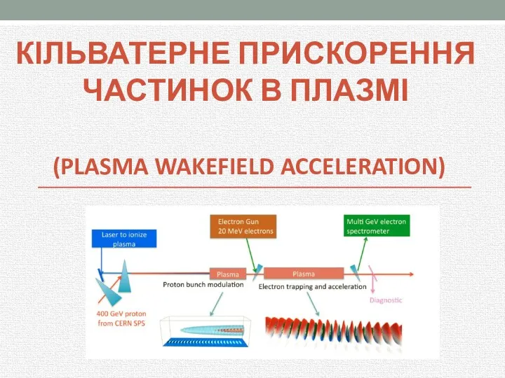 Кільватерне прискорення частинок в плазмі (plasma wakefield acceleration)
 Апаптоз патофизилогиясы
 Презентация Кабинет педагога-психолога
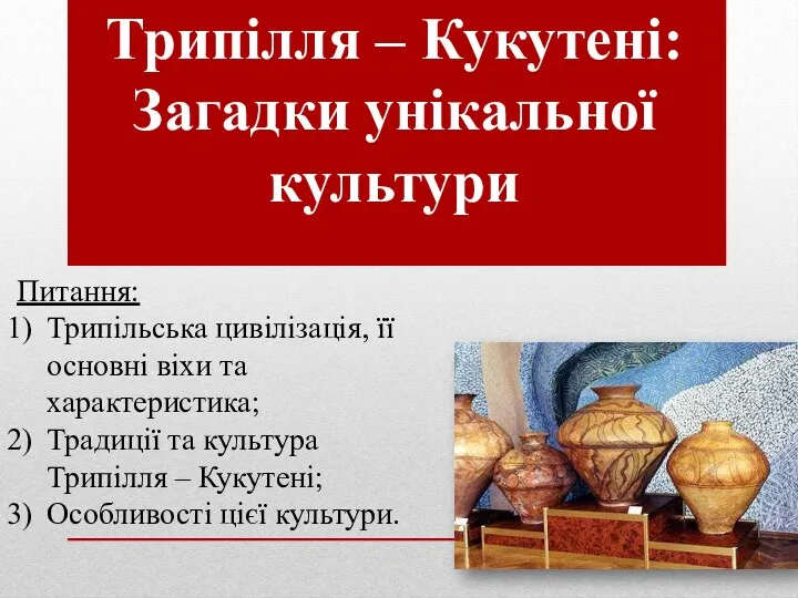 Трипілля – Кукутені. Загадки унікальної культури
 Русская архитектура XVI - XVII веков
 Портфолио Натальи Рудяковой. Маркетолог