- Tool and Spindle Calibration

Содержание
- 3. Why to calibrate a spindle? Robots need to be taught about tools in order to know
- 4. Objectives The objective of the spindle calibration procedure is to: Define the spindle center point (XYZ)
- 5. 2. Three probes / spikes One long probe (spike) One short probe (spike) A third spike
- 6. Step 1: Create a new spindle calibration From the tool calibration form, create a new spindle
- 7. Step 2: Teach short probe (Example based on a robot holding the spindle…) Teaching is required
- 8. Step 2: Teach short probe. Measure 1/3 The first ‘teach’ gives the values below:
- 9. Step 2: Teach short probe. Measure 2/3 And for the second ‘teach’:
- 10. Step 2: Teach short probe. Measure 3/3 Finally for the third ‘teach’:
- 11. Step 3: Measure short probe length The short probe length is then measured with the tool
- 12. Step 4: Measure long probe The short probe method is repeated with the long probe…
- 13. Step 4: Teach long probe. Measure 1/3 The first ‘teach’ gives the values below:
- 14. Step 4: Teach long probe. Measure 2/3 And for the second ‘teach’:
- 15. Step 4: Teach long probe. Measure 3/3 Finally for the third ‘teach’:
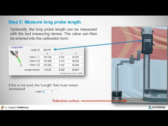
- 16. Step 5: Measure long probe length 222.915 If this is not used, the “Length” field must
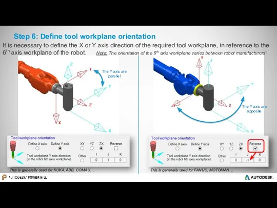
- 17. Step 6: Define tool workplane orientation This is generally used for KUKA, ABB, COMAU… This is
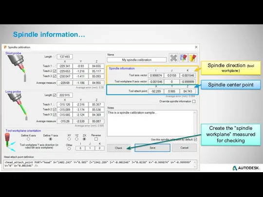
- 18. Spindle information… Spindle direction (tool workplane) Spindle center point Create the “spindle workplane” measured for checking
- 19. Step 7: Measure cutting tool length The cutting tool length is measured in the same way
- 20. Tool information is displayed 149.746 This information should go in the robot controller or in the
- 21. Tool length database Tool length can be stored in the tool length database as described below:
- 22. Step 8: Update CAD & simulation For the most accurate simulation the .mtd file can be
- 23. Autodesk ® PowerMill ® Robot Part on robot / External static spindle
- 24. Part-on-robot / External static spindle This will give the position of the robot spike tip from
- 25. The same as above needs to be done with the long probe... and the coordinate from
- 27. Скачать презентацию

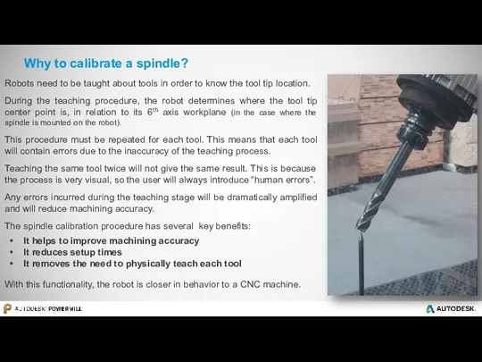
Why to calibrate a spindle?
Robots need to be taught about tools
Why to calibrate a spindle?
Robots need to be taught about tools
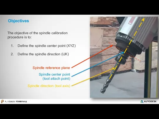
Objectives
The objective of the spindle calibration procedure is to:
Define the
Objectives
The objective of the spindle calibration procedure is to:
Define the
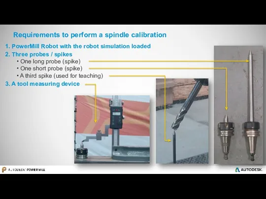
2. Three probes / spikes
One long probe (spike)
One short
2. Three probes / spikes
One long probe (spike)
One short
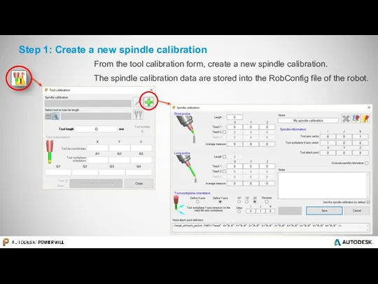
Step 1: Create a new spindle calibration
From the tool calibration form,
Step 1: Create a new spindle calibration
From the tool calibration form,
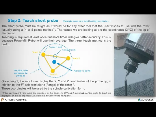
Step 2: Teach short probe (Example based on a robot holding
Step 2: Teach short probe (Example based on a robot holding
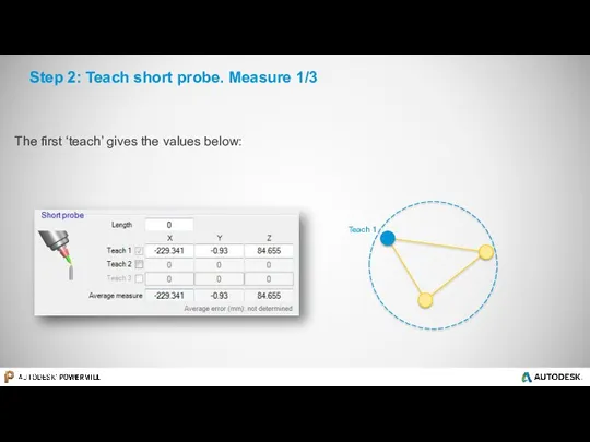
Step 2: Teach short probe. Measure 1/3
The first ‘teach’ gives the
Step 2: Teach short probe. Measure 1/3
The first ‘teach’ gives the
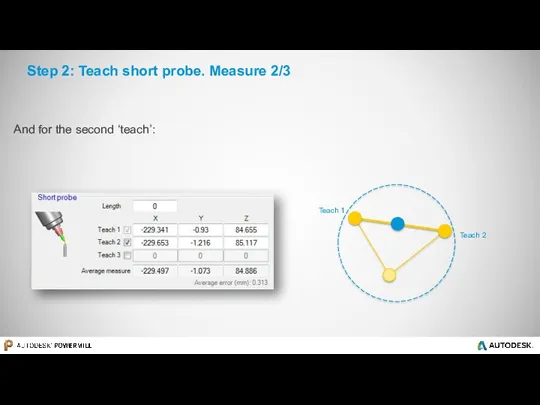
Step 2: Teach short probe. Measure 2/3
And for the second ‘teach’:
Step 2: Teach short probe. Measure 2/3
And for the second ‘teach’:
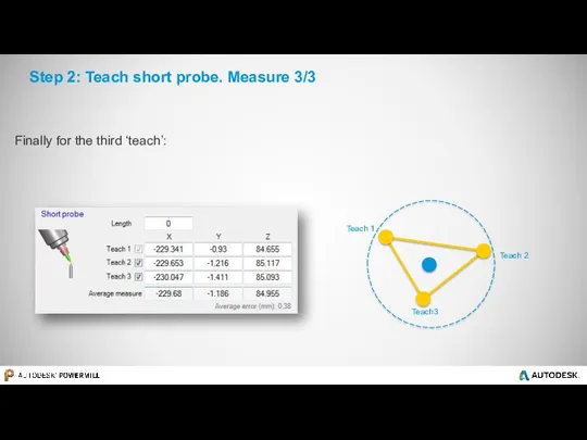
Step 2: Teach short probe. Measure 3/3
Finally for the third ‘teach’:
Step 2: Teach short probe. Measure 3/3
Finally for the third ‘teach’:
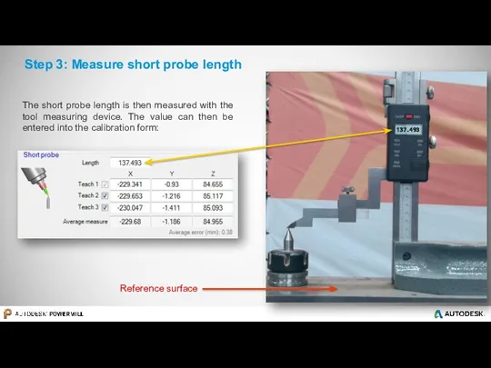
Step 3: Measure short probe length
The short probe length is then
Step 3: Measure short probe length
The short probe length is then
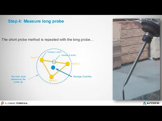
Step 4: Measure long probe
The short probe method is repeated with
Step 4: Measure long probe
The short probe method is repeated with
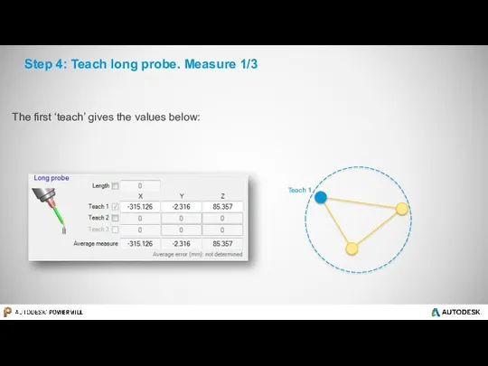
Step 4: Teach long probe. Measure 1/3
The first ‘teach’ gives the
Step 4: Teach long probe. Measure 1/3
The first ‘teach’ gives the
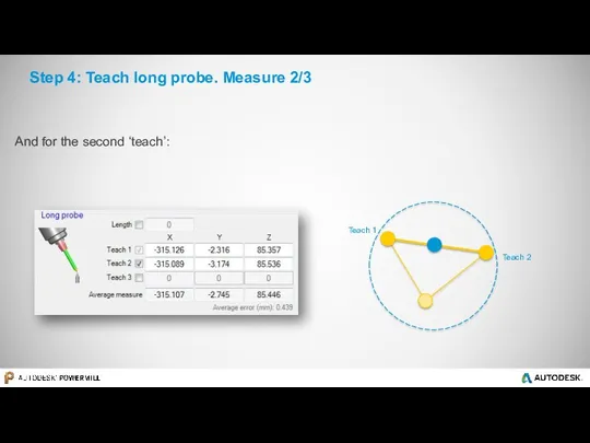
Step 4: Teach long probe. Measure 2/3
And for the second ‘teach’:
Step 4: Teach long probe. Measure 2/3
And for the second ‘teach’:
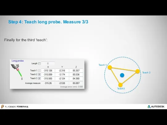
Step 4: Teach long probe. Measure 3/3
Finally for the third ‘teach’:
Step 4: Teach long probe. Measure 3/3
Finally for the third ‘teach’:
Step 5: Measure long probe length
222.915
If this is not used, the
Step 5: Measure long probe length
222.915
If this is not used, the
Step 6: Define tool workplane orientation
This is generally used for KUKA,
Step 6: Define tool workplane orientation
This is generally used for KUKA,
Spindle information…
Spindle direction (tool workplane)
Spindle center point
Create the “spindle workplane” measured
Spindle information…
Spindle direction (tool workplane)
Spindle center point
Create the “spindle workplane” measured
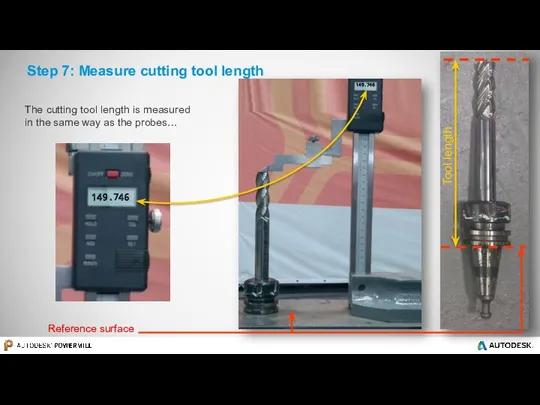
Step 7: Measure cutting tool length
The cutting tool length is measured
Step 7: Measure cutting tool length
The cutting tool length is measured
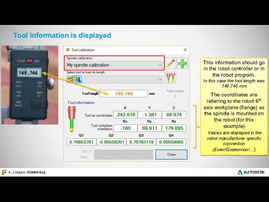
Tool information is displayed
149.746
This information should go in the robot controller
Tool information is displayed
149.746
This information should go in the robot controller
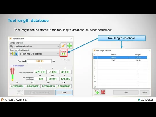
Tool length database
Tool length can be stored in the tool length
Tool length database
Tool length can be stored in the tool length
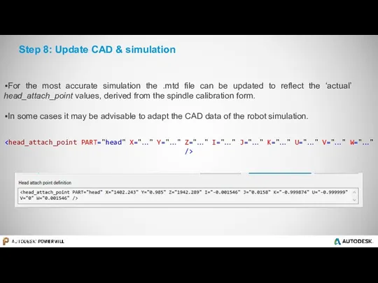
Step 8: Update CAD & simulation
For the most accurate simulation the
Step 8: Update CAD & simulation
For the most accurate simulation the

Autodesk ® PowerMill ® Robot
Part on robot / External static
Autodesk ® PowerMill ® Robot Part on robot / External static
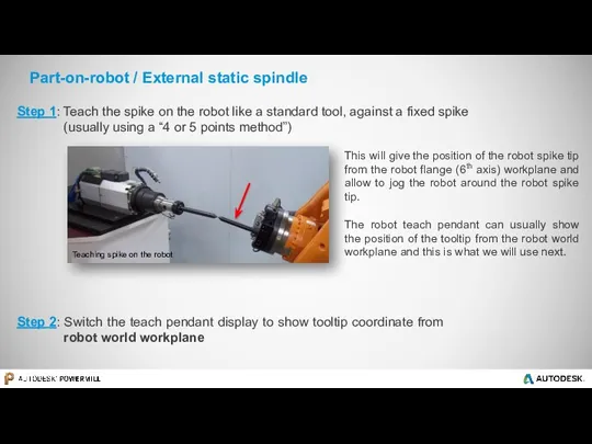
Part-on-robot / External static spindle
This will give the position of the
Part-on-robot / External static spindle
This will give the position of the
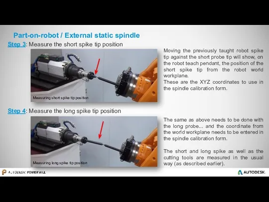
The same as above needs to be done with the long
The same as above needs to be done with the long
 Презентация Путешествие в страну Здоровья
 Физиология внешней нервной деятельности. Торможение условных рефлексов. Типы ВНД
 Инженерно-геологические изыскания
 Программа СОЦИАЛЬНО - ПЕДАГОГИЧЕСКАЯ ПОДДЕРЖКА УЧАЩИХСЯ В ОБРАЗОВАТЕЛЬНОМ УЧРЕЖДЕНИИ
 Инструкция по работе с дилерскими подсайтами
 Презентация От благодарных читателей
 Кредитная и банковская системы
 Роль иероглифов в китайской культуре
 Вымирание горбатых китов
 Отчет по неделе игры и игрушки (подготовительная группа)
 Отчет о работе НОУ 2014/15
 Аналитический отчёт
 Презентации учащихся 4 класса о космосе к дням науки
 Электродвигатели постоянного тока
 Конституционное право
 Теория фотоэффекта
 Надзор прокурора за исполнением судебных решений о применении принудительных мер медицинского характера
 Презентация1
 Презентация Принципы построения предметно-развивающей среды
 8 Марта
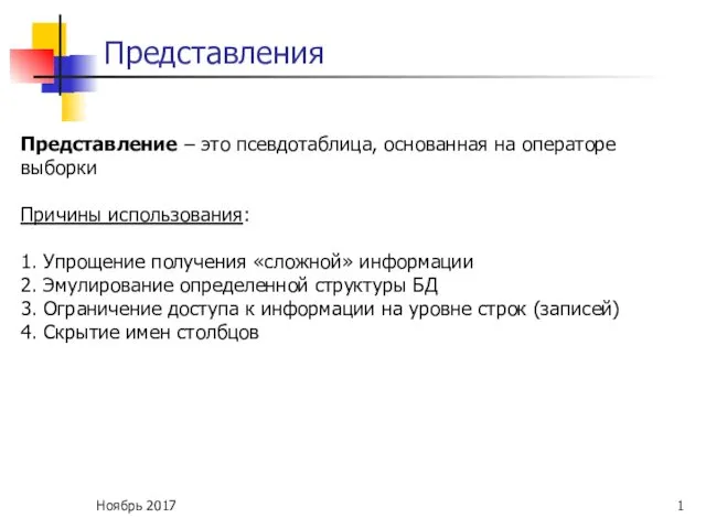 Представления
 Презентация к уроку по теме Алкены
 Курорт на черном море город Анапа
 Классный уголок
 Средства физического воспитания
 Интеллектуальная игра по географии Путешествие по странам и континентам
 Все вокруг-геометрия! Мастер-класс. Элементы Пентамино
 Системный анализ. (Лекция 2)