- Tube Bundle Frame Report

Содержание
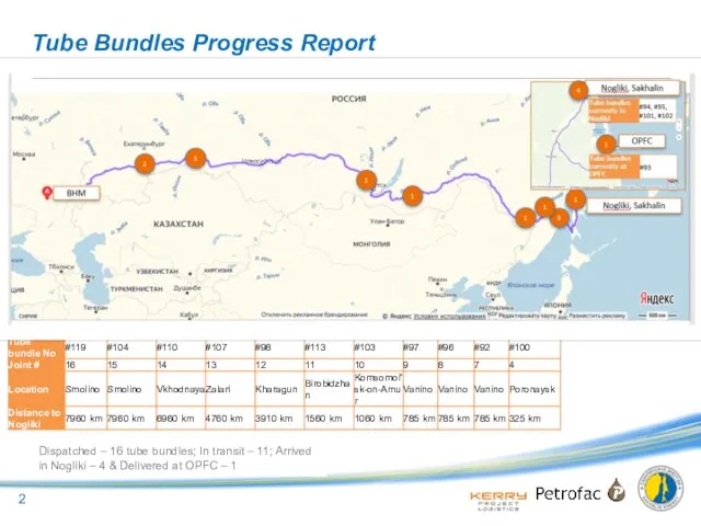
- 2. Tube Bundles Progress Report Dispatched – 16 tube bundles; In transit – 11; Arrived in Nogliki
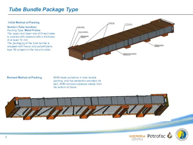
- 3. Tube Bundle Package Type Section (Tube bundles) Packing Type: Metal Frame The upper and lower row
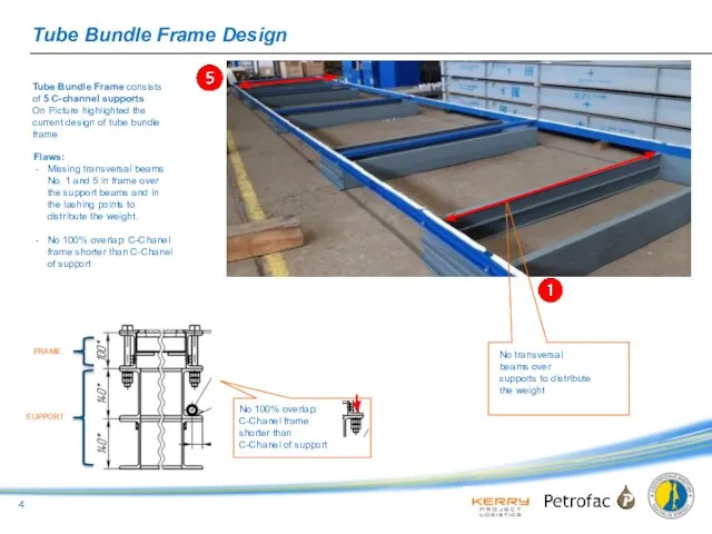
- 4. Tube Bundle Frame Design Tube Bundle Frame consists of 5 C-channel supports On Picture highlighted the
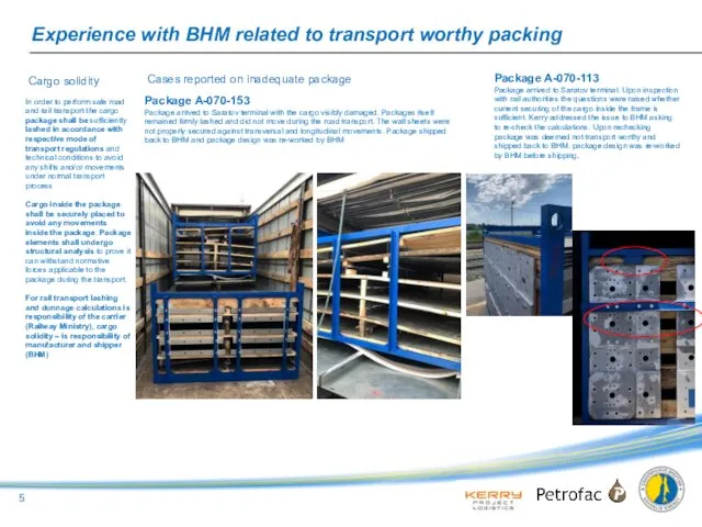
- 5. Experience with BHM related to transport worthy packing In order to perform safe road and rail
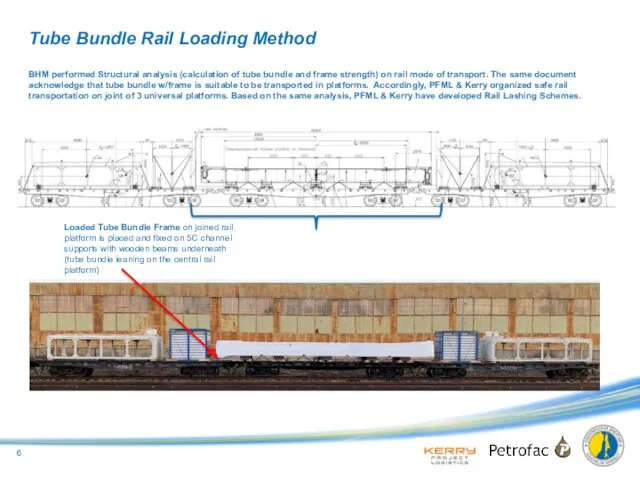
- 6. Tube Bundle Rail Loading Method BHM performed Structural analysis (calculation of tube bundle and frame strength)
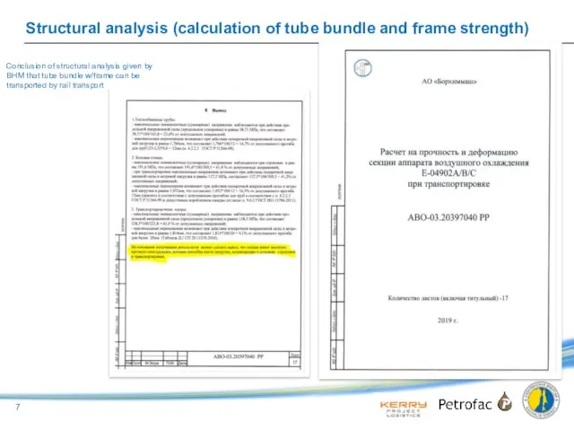
- 7. Structural analysis (calculation of tube bundle and frame strength) Conclusion of structural analysis given by BHM
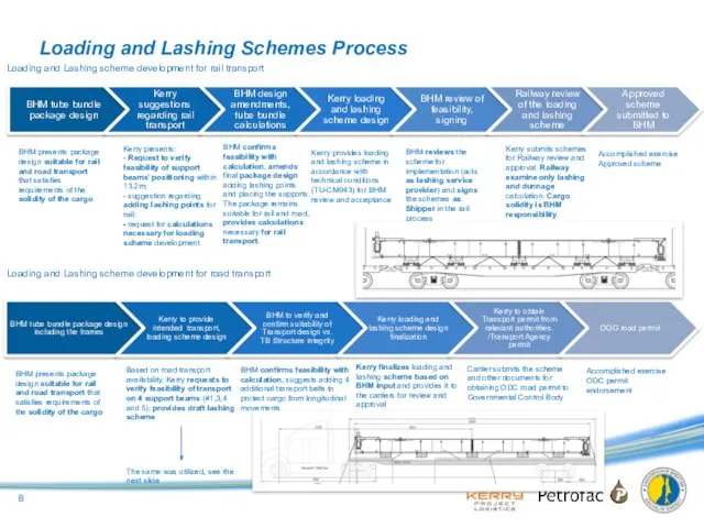
- 8. Loading and Lashing Schemes Process Loading and Lashing scheme development for rail transport Loading and Lashing
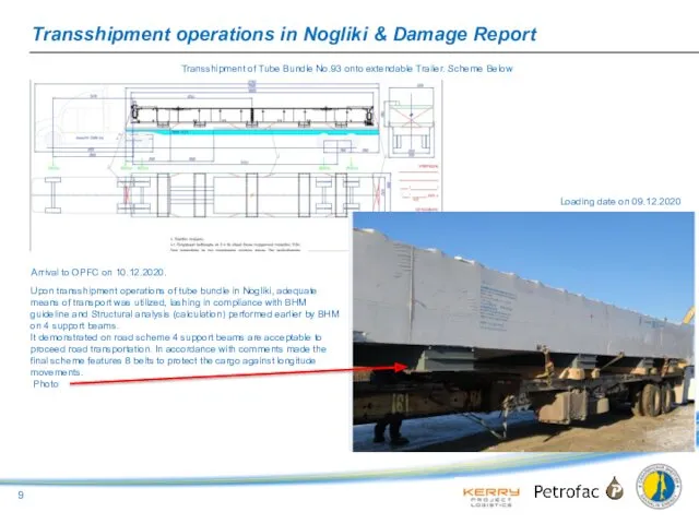
- 9. Transshipment operations in Nogliki & Damage Report Upon transshipment operations of tube bundle in Nogliki, adequate
- 10. Damage Report Root cause (hypothesis): Route cause hypothesis: There are no transversal beams to distribute tube
- 11. Inspection Visual Inspection of tube bundle # 102 on rail platforms Upon the notification of the
- 13. Скачать презентацию
Tube Bundles Progress Report
Dispatched – 16 tube bundles; In transit –
Tube Bundles Progress Report
Dispatched – 16 tube bundles; In transit –
Tube Bundle Package Type
Section (Tube bundles)
Packing Type: Metal Frame
The
Tube Bundle Package Type
Section (Tube bundles)
Packing Type: Metal Frame
The
Tube Bundle Frame Design
Tube Bundle Frame consists of 5 C-channel
Tube Bundle Frame Design
Tube Bundle Frame consists of 5 C-channel
Experience with BHM related to transport worthy packing
In order to
Experience with BHM related to transport worthy packing
In order to
Tube Bundle Rail Loading Method
BHM performed Structural analysis (calculation of
Tube Bundle Rail Loading Method
BHM performed Structural analysis (calculation of
Structural analysis (calculation of tube bundle and frame strength)
Conclusion of structural
Structural analysis (calculation of tube bundle and frame strength)
Conclusion of structural
Loading and Lashing Schemes Process
Loading and Lashing scheme development for rail
Loading and Lashing Schemes Process
Loading and Lashing scheme development for rail
Transshipment operations in Nogliki & Damage Report
Upon transshipment operations of
Transshipment operations in Nogliki & Damage Report
Upon transshipment operations of
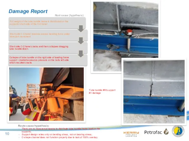
Damage Report
Root cause (hypothesis):
Route cause hypothesis:
There are no transversal beams
Damage Report
Root cause (hypothesis):
Route cause hypothesis:
There are no transversal beams
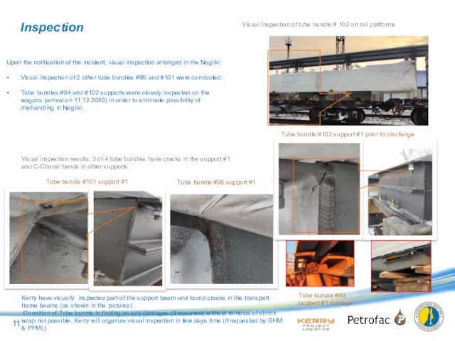
Inspection
Visual Inspection of tube bundle # 102 on rail platforms
Upon
Inspection
Visual Inspection of tube bundle # 102 on rail platforms
Upon
 Актуальные вопросы преподавания предмета Основы религиозных культур и светской этики
 Менингококковая инфекция. Менингеальный синдром в клинике инфекционных болезней
 Преступления против основ конституционного строя и безопасности государства
 Программы для занятий
 Операциялық жүйе
 Общие сведения о программе 1С: Предприятие - ЗУП. Начальное заполнение информационной базы в 1С:
 Кто говорит, что на войне не страшно, тот ничего не знает о войне. 9 мая - День Победы
 Рисунок птицы в простой графическом редакторе
 Методическая разработка образовательной программы по образовательной области ПОЗНАВАТЕЛЬНОЕ РАЗВИТИЕ. Тема Проектная деятельность с детьми старшего дошкольного возраста
 Дизартрии у детей. Взгляд невролога
 Измерение углов. Транспортир.
 Цветотерапия - как средство снятия стресса
 Промышленный дизайн
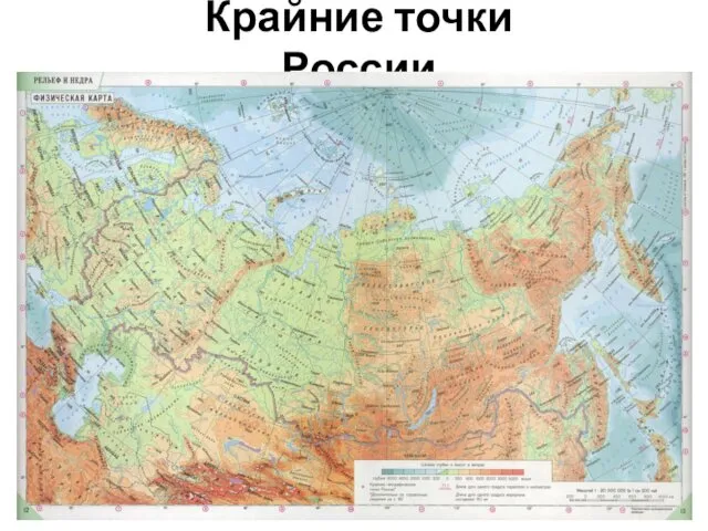 Крайние точки России
 Мастер-класс Розы из кленовых листьев
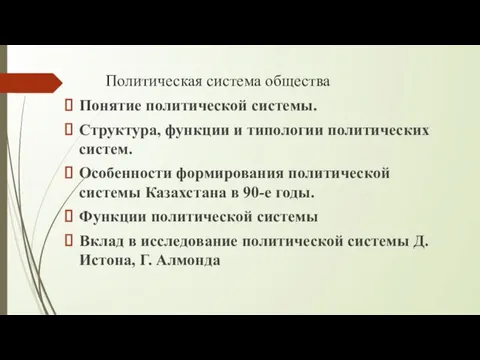 Политическая система общества
 АҚ Өскемен құс фабрикасы
 Utilajul frigorific din sala de comerț
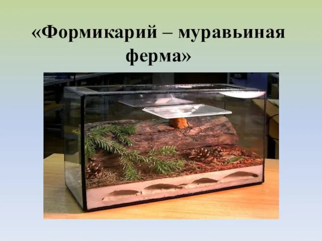 Формикарий – муравьиная ферма
 Серия мин ТМ-62
 Русский алфавит или азбука
 МАТЕМАТИКА Угол
 Развитие и воспитание учащихся в процессе обучения биологии
 Способы доказательств теоремы Пифагора
 Образование как общественное явление
 Товароведные характеристики и особенности реализации ювелирных изделий
 Презентация Детская организация РОСТ
 Размещение объявлений на ДомКлик для клиентов и партнеров