- Введение в оптические транспортные сети OTN

Содержание
- 2. Передача трафика поверх сети SDH
- 3. Преимущества концепции OTN/OTH
- 4. Сводка Рекомендаций МСЭ-Т по оптическим транспортным сетям OTN
- 5. Электрический и оптический уровни OTN
- 6. Электро-оптический уровень OTN
- 7. Подуровни электро-оптического уровня OTN The electro-optical layer is composed of three functional sublayers: The client signal
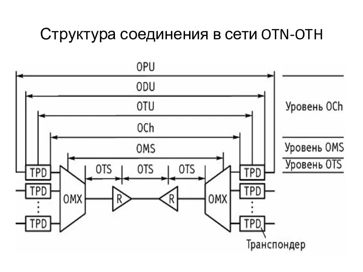
- 8. Структура соединения в сети OTN-OTH
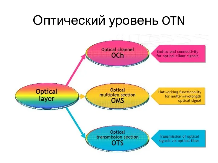
- 9. Оптический уровень OTN
- 10. Подуровни оптического уровня OTN(1) The optical layer is composed of three functional sublayers: OCh, OMS, OTS.
- 11. Подуровни оптического уровня OTN(2) Multiplexing several optical channels creates the Optical Multiplex Section (OMS) layer. It
- 12. Подуровни оптического уровня OTN(3) The Optical Transmission Section (OTS) layer provides transport function for the OMS
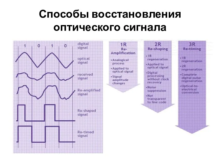
- 13. Способы восстановления оптического сигнала
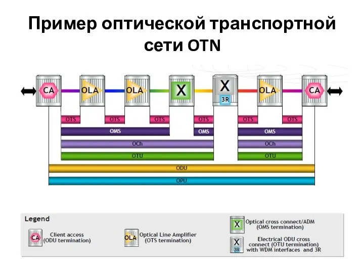
- 14. Пример оптической транспортной сети OTN
- 15. Организация участков оптической транспортной сети (1) The client access (CA) equipment mappes the client signal, e.g.
- 16. Организация участков оптической транспортной сети (2) The optical transmission section OTS with its associated overhead is
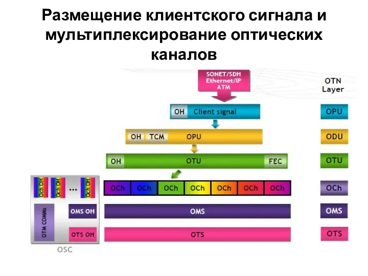
- 17. Размещение клиентского сигнала и мультиплексирование оптических каналов
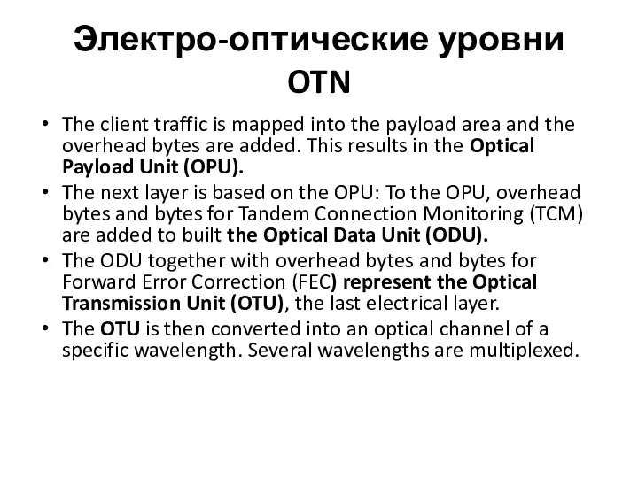
- 18. Электро-оптические уровни OTN The client traffic is mapped into the payload area and the overhead bytes
- 19. Секция мультиплексирования OMS и секция передачи OTS Additional overhead bytes for each optical channel are added.
- 20. Оптические транспортные модули(1)
- 21. Оптические транспортные модули(1)
- 22. Структуры транспортных модулей(1)
- 23. Структуры транспортных модулей(2) In the OTM-0.m the “0” refers to a special case of reduced functionality:
- 24. Схема мультиплексирования OTM
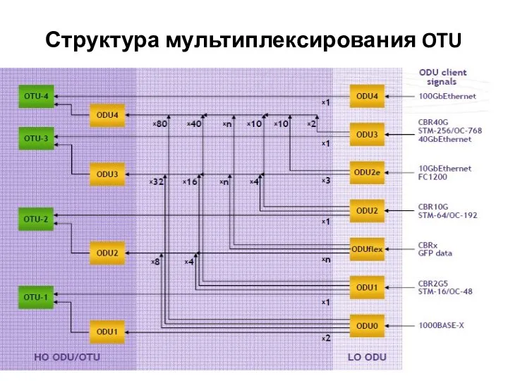
- 25. Структура мультиплексирования OTU
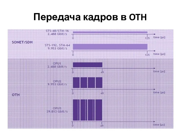
- 26. Передача кадров в OTH
- 27. Структура кадра OTH
- 28. Структура заголовка OTUk(1)
- 29. Структура заголовка OTUk(2)
- 30. Структура заголовка OTUk(3)
- 31. Структура заголовка ODU (1)
- 32. Структура заголовка ODU (2)
- 33. Структура заголовка OPU
- 34. Уровни контроля модемных соединений ТСМ
- 35. Проверочное поле FEC
- 37. Скачать презентацию
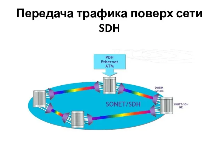
Передача трафика поверх сети SDH
Передача трафика поверх сети SDH
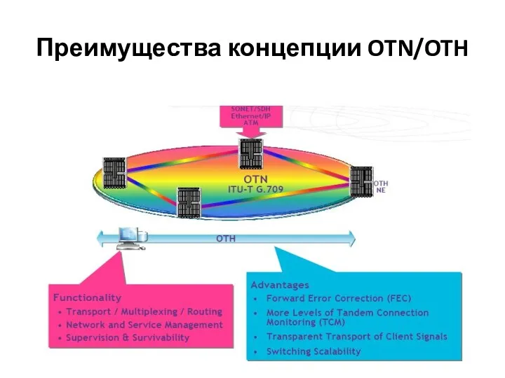
Преимущества концепции OTN/OTH
Преимущества концепции OTN/OTH
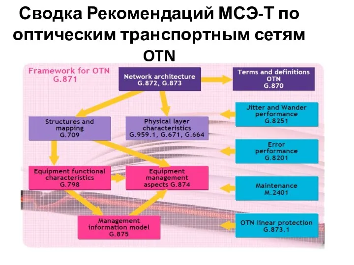
Сводка Рекомендаций МСЭ-Т по оптическим транспортным сетям OTN
Сводка Рекомендаций МСЭ-Т по оптическим транспортным сетям OTN

Электрический и оптический уровни OTN
Электрический и оптический уровни OTN
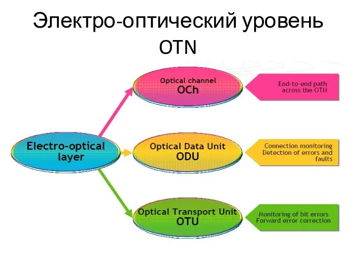
Электро-оптический уровень OTN
Электро-оптический уровень OTN
Подуровни электро-оптического уровня OTN
The electro-optical layer is composed of three functional
Подуровни электро-оптического уровня OTN
The electro-optical layer is composed of three functional
Структура соединения в сети OTN-OTH
Структура соединения в сети OTN-OTH
Оптический уровень OTN
Оптический уровень OTN
Подуровни оптического уровня OTN(1)
The optical layer is composed of three functional
Подуровни оптического уровня OTN(1)
The optical layer is composed of three functional
Подуровни оптического уровня OTN(2)
Multiplexing several optical channels creates the Optical Multiplex
Подуровни оптического уровня OTN(2)
Multiplexing several optical channels creates the Optical Multiplex
Подуровни оптического уровня OTN(3)
The Optical Transmission Section (OTS) layer provides transport
Подуровни оптического уровня OTN(3)
The Optical Transmission Section (OTS) layer provides transport
Способы восстановления оптического сигнала
Способы восстановления оптического сигнала
Пример оптической транспортной сети OTN
Пример оптической транспортной сети OTN
Организация участков оптической транспортной сети (1)
The client access (CA) equipment mappes
Организация участков оптической транспортной сети (1)
The client access (CA) equipment mappes
Организация участков оптической транспортной сети (2)
The optical transmission section OTS with
Организация участков оптической транспортной сети (2)
The optical transmission section OTS with
Размещение клиентского сигнала и мультиплексирование оптических каналов
Размещение клиентского сигнала и мультиплексирование оптических каналов
Электро-оптические уровни OTN
The client traffic is mapped into the payload area
Электро-оптические уровни OTN
The client traffic is mapped into the payload area
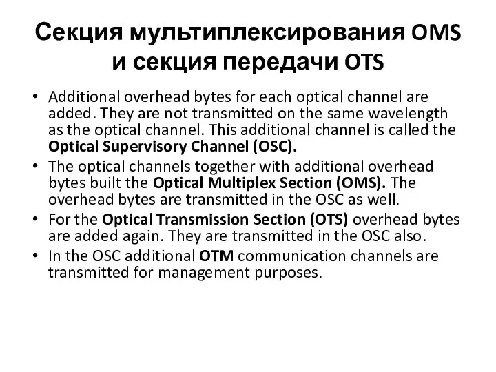
Секция мультиплексирования OMS и секция передачи OTS
Additional overhead bytes for each
Секция мультиплексирования OMS и секция передачи OTS
Additional overhead bytes for each
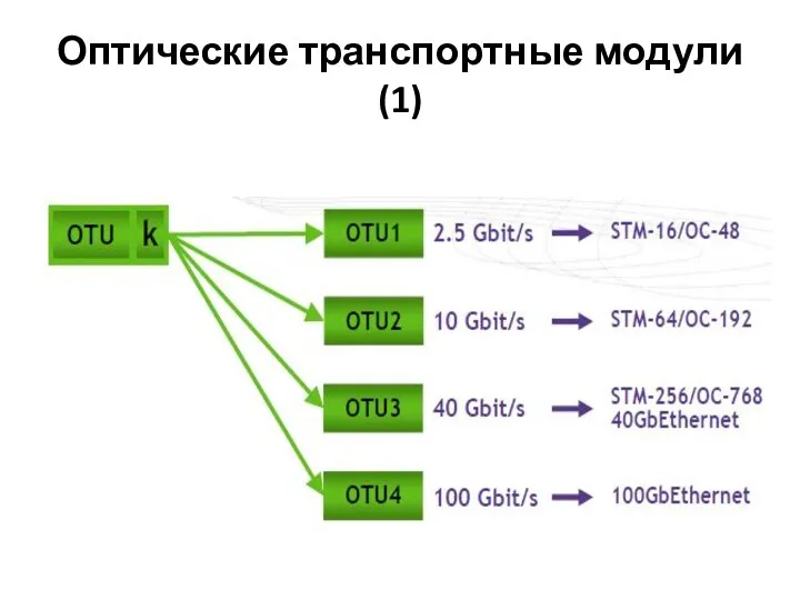
Оптические транспортные модули(1)
Оптические транспортные модули(1)
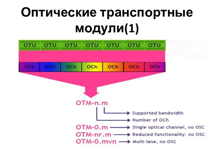
Оптические транспортные модули(1)
Оптические транспортные модули(1)
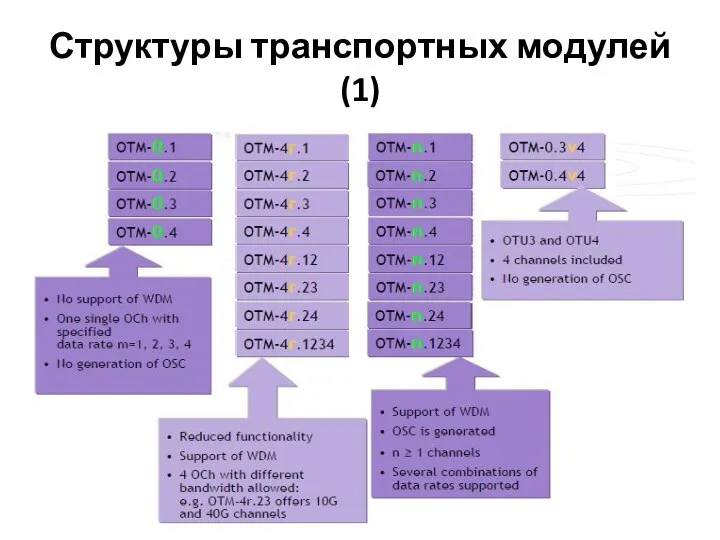
Структуры транспортных модулей(1)
Структуры транспортных модулей(1)
Структуры транспортных модулей(2)
In the OTM-0.m the “0” refers to a special
Структуры транспортных модулей(2)
In the OTM-0.m the “0” refers to a special
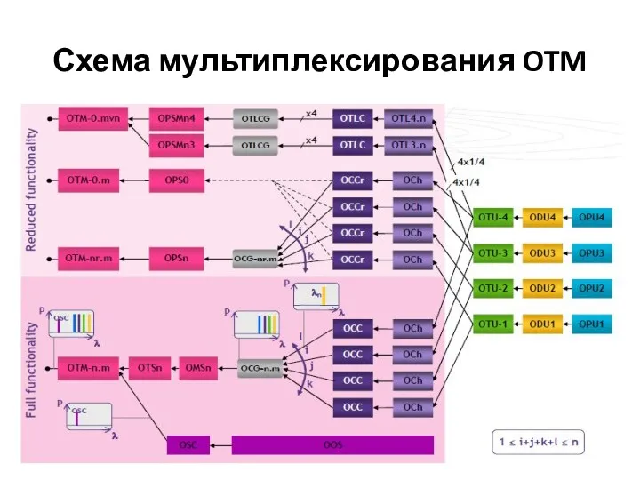
Схема мультиплексирования OTM
Схема мультиплексирования OTM
Структура мультиплексирования OTU
Структура мультиплексирования OTU
Передача кадров в OTH
Передача кадров в OTH
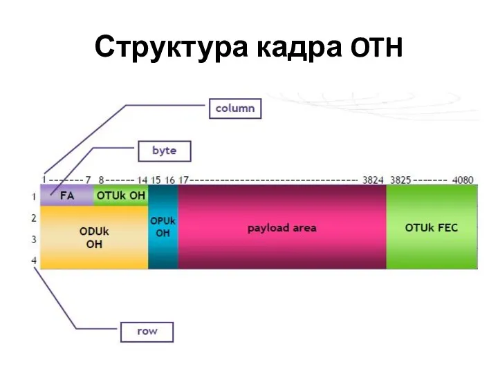
Структура кадра OTH
Структура кадра OTH
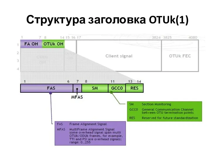
Структура заголовка OTUk(1)
Структура заголовка OTUk(1)
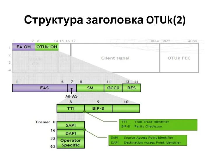
Структура заголовка OTUk(2)
Структура заголовка OTUk(2)
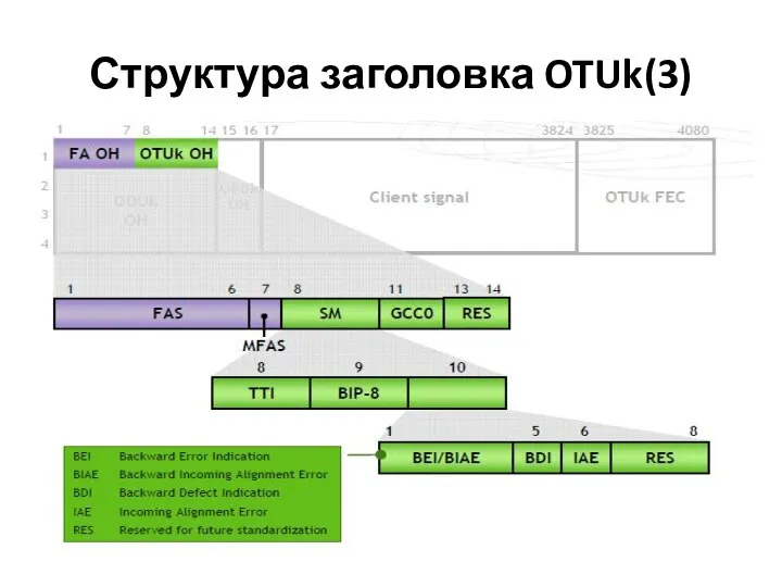
Структура заголовка OTUk(3)
Структура заголовка OTUk(3)
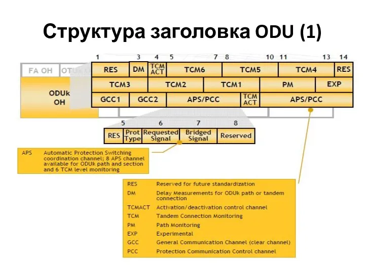
Структура заголовка ODU (1)
Структура заголовка ODU (1)
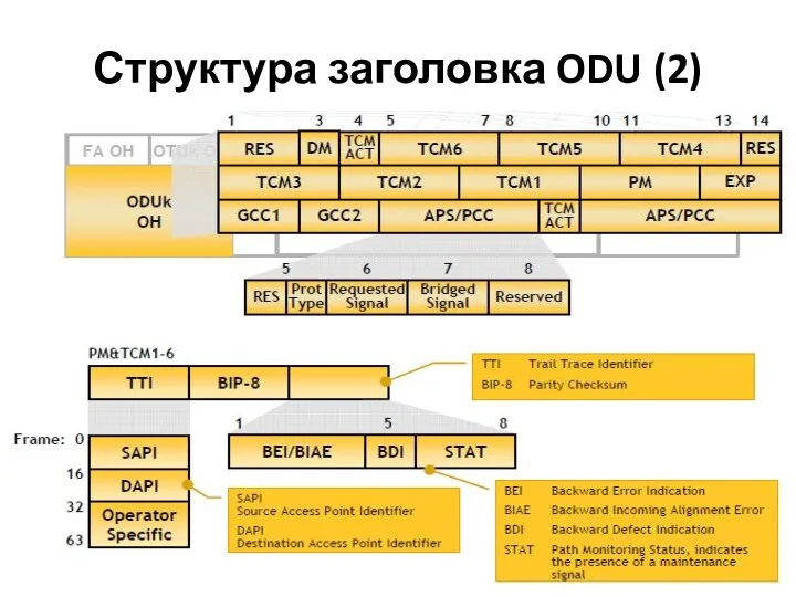
Структура заголовка ODU (2)
Структура заголовка ODU (2)
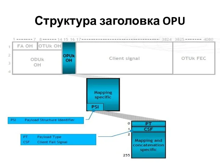
Структура заголовка OPU
Структура заголовка OPU
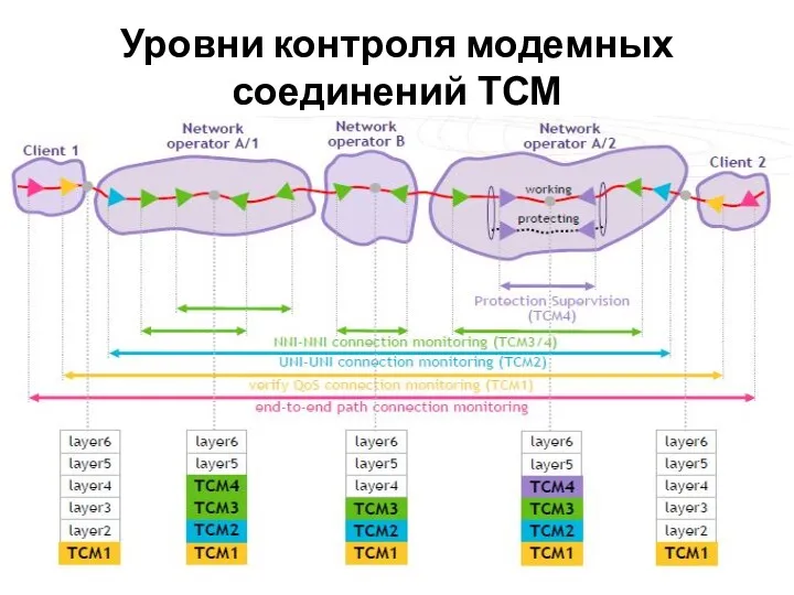
Уровни контроля модемных соединений ТСМ
Уровни контроля модемных соединений ТСМ
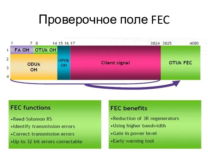
Проверочное поле FEC
Проверочное поле FEC
 ММ-задание по R-диагностике заболеваний органов дыхания
 Магнитное поле.Вектор магнитной индукции
 Единый деловой стиль одежды в школе
 Детские вопросы и как на них отвечать
 Найди недостающий фрагмент. Развивающая игра для детей
 Инновационный менеджмент. Лекция 2
 Приглашение на свадьбу
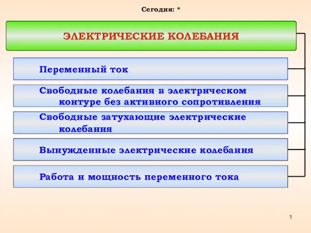 Электрические колебания. Переменный ток
 родительское собрание
 Bekanntschaft. Thema 1
 Кодирование информации, 8 класс
 книга, презентация
 Лексикология и ее разделы
 Особенности проекта НВАЭС-2
 Профилактика наследственных заболеваний. (Лекция 6)
 Поговорил бы кто со мной...Телефон доверия.
 Моя профессия педагог-психолог
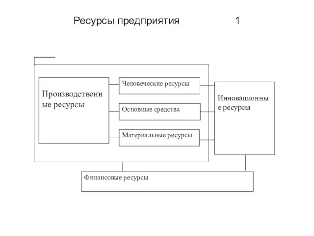 Ресурсы предприятия
 Презентация. Летний оздоровительный лагерь.
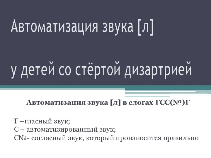 Автоматизация звука [Л]
 Вопросы знатокам 10-11 классов
 Дорожные знаки. Что расскажет улица
 Культура Ярославского края в 19 веке. 4 класс
 Толкование норм права
 Метод качественной оценки риска
 Эволюция менеджмента
 Город сквозь времена и страны
 iGRUShKI_IZ_POROLONA_aGAFONOVA_r_R