- High Lift Devices

Содержание
- 2. PURPOSE OF HIGH LIFT DEVICES To reduce the take-off and landing distances.
- 3. FLAPS A hinged portion of the trailing or leading edge which can be deflected downwards and
- 4. PLAIN FLAP Simple construction, good increase of lift, but high drag. Mainly used on low speed
- 5. SPLIT FLAP It is a part of the lower surface of the wing trailing edge, the
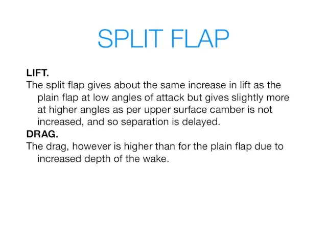
- 6. SPLIT FLAP LIFT. The split flap gives about the same increase in lift as the plain
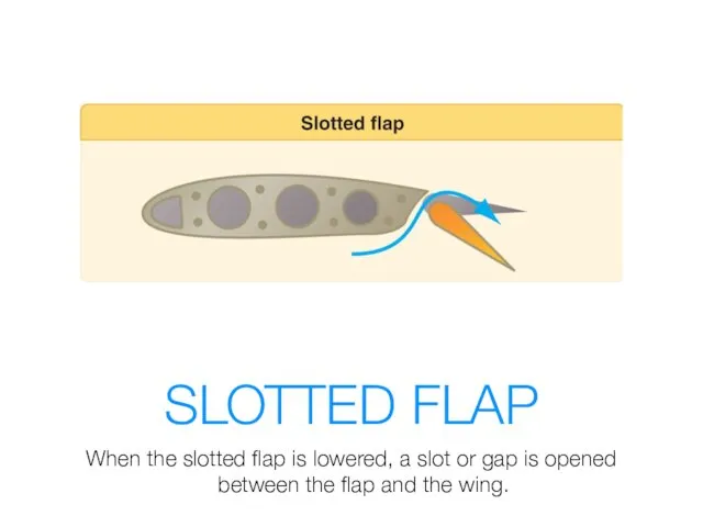
- 7. SLOTTED FLAP When the slotted flap is lowered, a slot or gap is opened between the
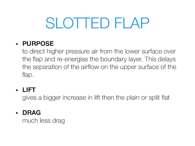
- 8. SLOTTED FLAP PURPOSE to direct higher pressure air from the lower surface over the flap and
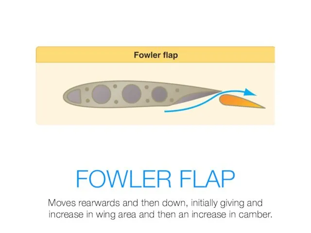
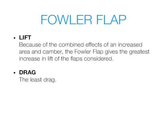
- 9. FOWLER FLAP Moves rearwards and then down, initially giving and increase in wing area and then
- 10. FOWLER FLAP LIFT Because of the combined effects of an increased area and camber, the Fowler
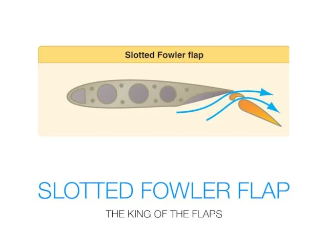
- 11. SLOTTED FOWLER FLAP THE KING OF THE FLAPS
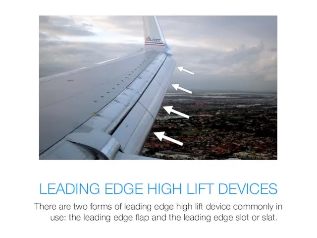
- 12. LEADING EDGE HIGH LIFT DEVICES There are two forms of leading edge high lift device commonly
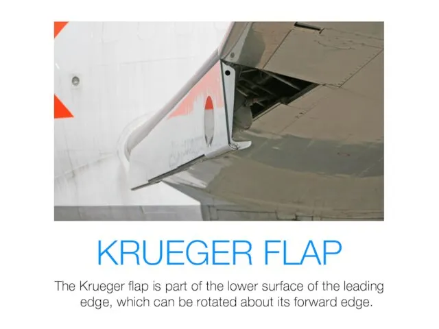
- 13. KRUEGER FLAP The Krueger flap is part of the lower surface of the leading edge, which
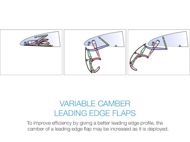
- 14. VARIABLE CAMBER LEADING EDGE FLAPS To improve efficiency by giving a better leading edge profile, the
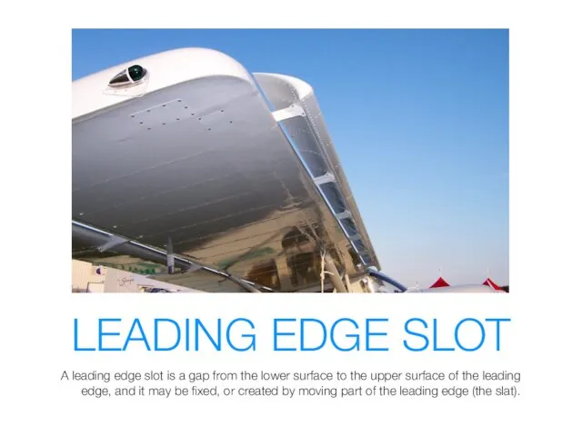
- 15. LEADING EDGE SLOT A leading edge slot is a gap from the lower surface to the
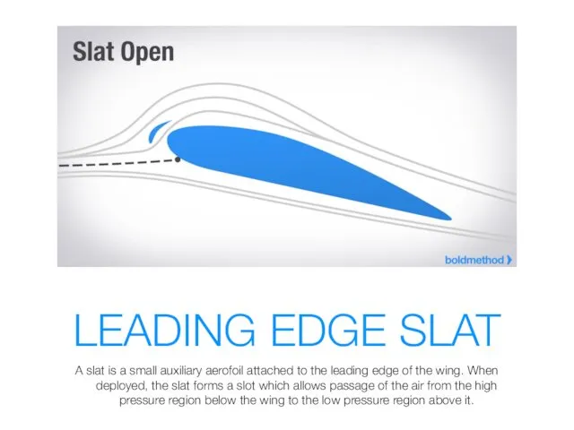
- 16. LEADING EDGE SLAT A slat is a small auxiliary aerofoil attached to the leading edge of
- 17. AUTOMATIC SLOTS On some aircraft the slots are not controlled by a pilot, but operate automatically.
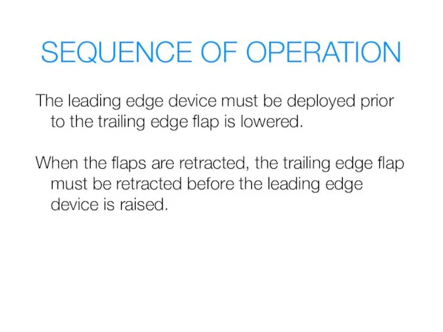
- 18. SEQUENCE OF OPERATION The leading edge device must be deployed prior to the trailing edge flap
- 19. ASYMMETRY OF HIGH LIFT DEVICES ROLL! YAW!
- 20. FLAP LOAD RELIEF SYSTEM
- 21. FLAPS OPERATION
- 23. Скачать презентацию
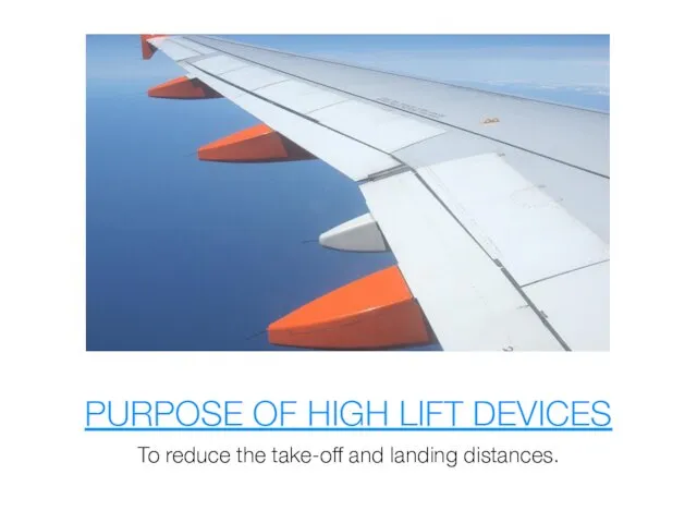
PURPOSE OF HIGH LIFT DEVICES
To reduce the take-off and landing distances.
PURPOSE OF HIGH LIFT DEVICES
To reduce the take-off and landing distances.
FLAPS
A hinged portion of the trailing or leading edge which can
FLAPS
A hinged portion of the trailing or leading edge which can
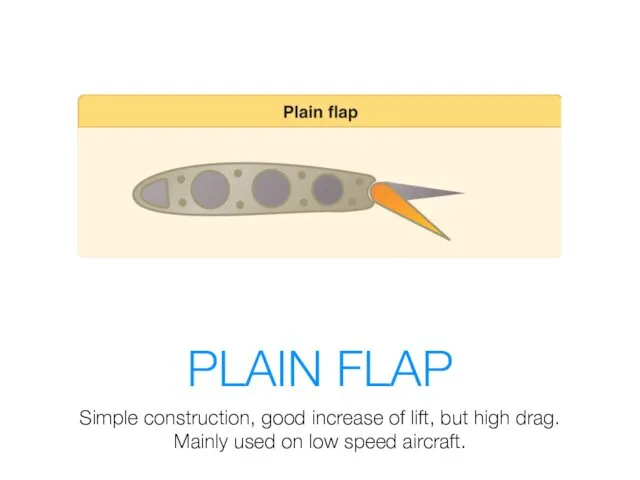
PLAIN FLAP
Simple construction, good increase of lift, but high drag.
Mainly used
PLAIN FLAP
Simple construction, good increase of lift, but high drag.
Mainly used
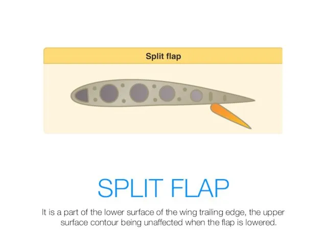
SPLIT FLAP
It is a part of the lower surface of the
SPLIT FLAP
It is a part of the lower surface of the
SPLIT FLAP
LIFT.
The split flap gives about the same increase in lift
SPLIT FLAP
LIFT.
The split flap gives about the same increase in lift
SLOTTED FLAP
When the slotted flap is lowered, a slot or gap
SLOTTED FLAP
When the slotted flap is lowered, a slot or gap
SLOTTED FLAP
PURPOSE
to direct higher pressure air from the lower surface over
SLOTTED FLAP
PURPOSE to direct higher pressure air from the lower surface over
FOWLER FLAP
Moves rearwards and then down, initially giving and increase in
FOWLER FLAP
Moves rearwards and then down, initially giving and increase in
FOWLER FLAP
LIFT
Because of the combined effects of an increased area and
FOWLER FLAP
LIFT Because of the combined effects of an increased area and
SLOTTED FOWLER FLAP
THE KING OF THE FLAPS
SLOTTED FOWLER FLAP
THE KING OF THE FLAPS
LEADING EDGE HIGH LIFT DEVICES
There are two forms of leading edge
LEADING EDGE HIGH LIFT DEVICES
There are two forms of leading edge
KRUEGER FLAP
The Krueger flap is part of the lower surface of
KRUEGER FLAP
The Krueger flap is part of the lower surface of
VARIABLE CAMBER
LEADING EDGE FLAPS
To improve efficiency by giving a better leading
VARIABLE CAMBER
LEADING EDGE FLAPS
To improve efficiency by giving a better leading
LEADING EDGE SLOT
A leading edge slot is a gap from the
LEADING EDGE SLOT
A leading edge slot is a gap from the
LEADING EDGE SLAT
A slat is a small auxiliary aerofoil attached to
LEADING EDGE SLAT
A slat is a small auxiliary aerofoil attached to
AUTOMATIC SLOTS
On some aircraft the slots are not controlled by a
AUTOMATIC SLOTS
On some aircraft the slots are not controlled by a
SEQUENCE OF OPERATION
The leading edge device must be deployed prior to
SEQUENCE OF OPERATION
The leading edge device must be deployed prior to
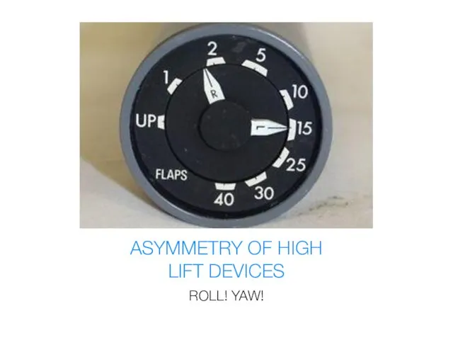
ASYMMETRY OF HIGH
LIFT DEVICES
ROLL! YAW!
ASYMMETRY OF HIGH
LIFT DEVICES
ROLL! YAW!

FLAP LOAD RELIEF SYSTEM
FLAP LOAD RELIEF SYSTEM
FLAPS OPERATION
FLAPS OPERATION
Похожие презентации
 Суффиксы существительных -er (-or), -ist, -ian, -ity, -ing, -hood, -ment, -ness, -y, -th, -ant, -ism, -ure, -ship
 Possessive pronouns
 Well-being and money
 [ʤ] – перед гласными e, i, y
 Спряжение глагола to be
 My dream restaurant
 Jeopardy
 Our approach for support in project’s development process
 English Language Day
 Образование множественного числа существительных.
 Environmental pollution. Water pollution
 Особенности подготовки к ЕГЭ по английскому языку (раздел Говорение. Сравнение фотографий (задание #4)
 phpv0d5iZ_Present-Simple-vs-Present-Continuous
 Linkin Park
 Present Tenses
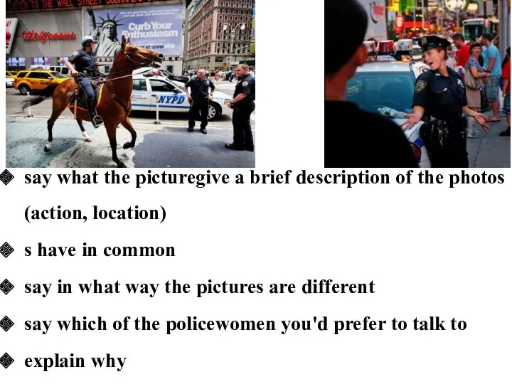 Сравнение. Полицейские
 Present Simple vs Present Continuous
 What are you wearing
 Past Tenses
 Language and speech. Types of speech
 My best friend
 Quantifiers. What are quantifiers?
 Information Visualization Course
 The secrets of the nature
 Food
Food Learn the colours
 Lexical stylistic devices