- th-Tune new firmware. Programmers’ guide

Содержание
- 2. Introduction This presentation provides some basic explanation to develop an application with one th-Tune display connected
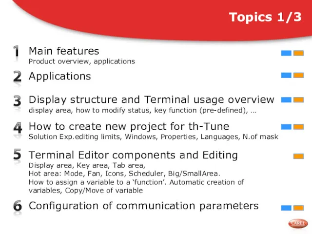
- 3. Topics 1/3 Main features Product overview, applications Applications Display structure and Terminal usage overview display area,
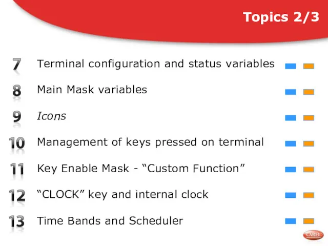
- 4. Topics 2/3 Terminal configuration and status variables Main Mask variables Icons Key Enable Mask - “Custom
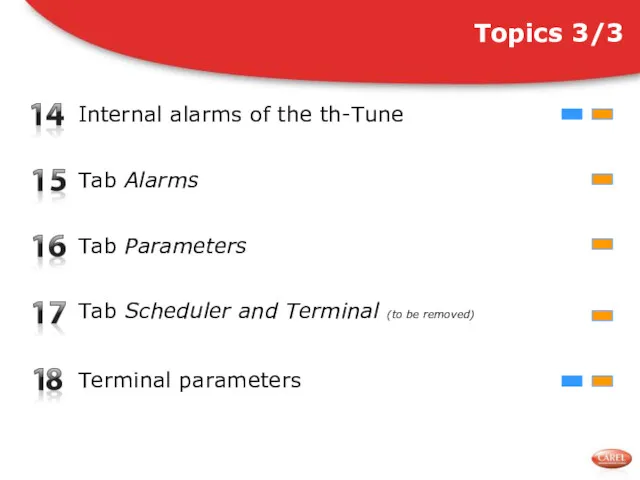
- 5. Topics 3/3 Internal alarms of the th-Tune Terminal parameters Tab Alarms Tab Scheduler and Terminal (to
- 6. Standard power supply (115..230 Vac) or 24 Vac/Vdc Temperature and Humidity measurements Internal clock Compatible with
- 7. Easy To use User Terminal as well as Commissioning terminal Compatible with the most common wall
- 8. “Dummy” user interface (predefined keyfunction & navigation must be supported by the controller) Can be used
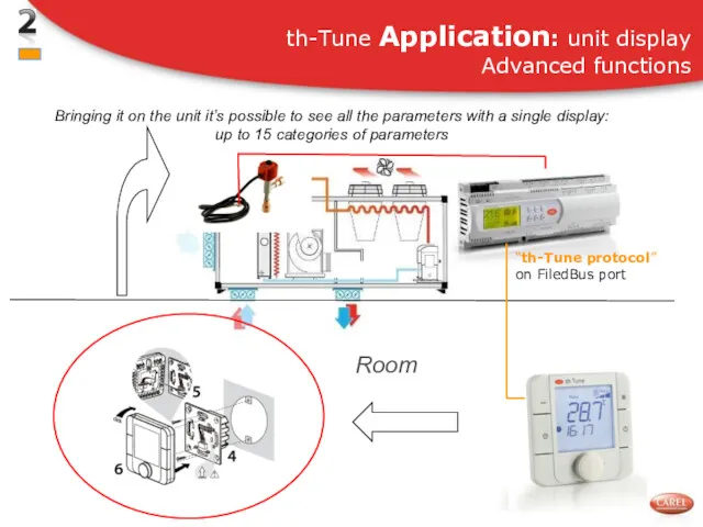
- 9. th-Tune Application: unit display Advanced functions Bringing it on the unit it’s possible to see all
- 10. th-Tune Application: user terminal for basic settings ON-OFF, setpoints, temperature and humidity measurement, function enabling, TIME
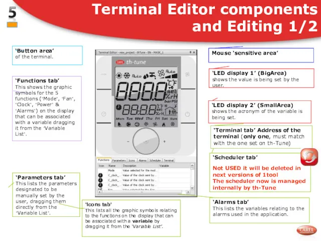
- 11. Display structure and Terminal usage overview 1/3 “Mode” area “Fan” area “BigArea” Shows the value of
- 12. Display structure and Terminal usage overview 2/3 “Mode” When pressing the ‘Mode’ button, the symbol relating
- 13. Display structure and Terminal usage overview 3/3 “Mode”+ “Clock” When pressing these buttons together for 5
- 14. Specific Terminal Editor thTune terminal: only ‘EN’ language Only 1 mask/terminal Most part of editing menu/tools/properties
- 15. Check list of variables available in Modbus Use de Modbus master DEMO to understand how it
- 16. Terminal Editor components and Editing 1/2
- 17. How to associate a Variable to a Symbol/Function/Status/Variable drag&drop from Variablelist to Symbol/Function/Status/Variable or to Listview
- 18. Inside project you must set this comunication parameters on FieldBus port COM_PROTOCOL_FIELDBUS=19 (th-Tune protocol) COM_BAUDRATE_FIELDBUS=4 (19200baud)
- 19. Make sure that baudrate and address on the th-Tune are correct: see section 18 for th-Tune
- 20. There are some variables indicating the status and the configuration of the terminal that must be
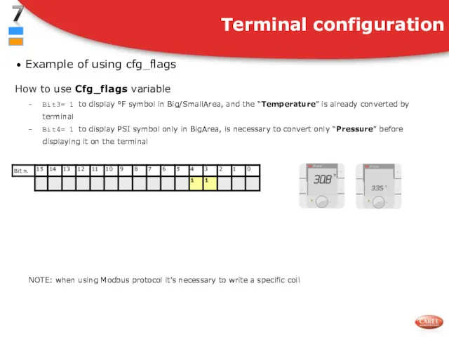
- 21. Use Cfg_flags variable to configure the terminal Terminal configuration Cfg_flags NOTE: when using Modbus protocol, it’s
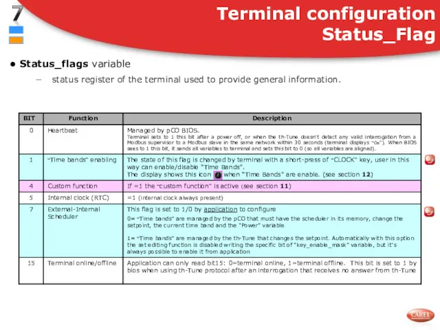
- 22. Status_flags variable status register of the terminal used to provide general information. Terminal configuration Status_Flag
- 23. How to use Cfg_flags variable Bit3= 1 to display °F symbol in Big/SmallArea, and the “Temperature”
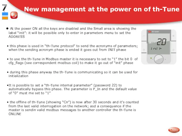
- 24. New management at the power on of th-Tune At the power ON all the keys are
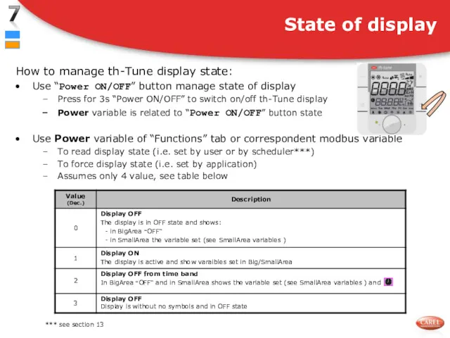
- 25. How to manage th-Tune display state: Use “Power ON/OFF” button manage state of display Press for
- 26. The “Mode” area includes several symbols: heating, cooling, etc To change mode press the Mode button
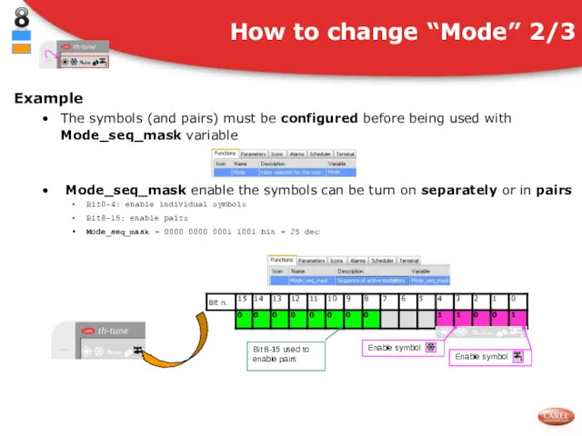
- 27. Example The symbols (and pairs) must be configured before being used with Mode_seq_mask variable Mode_seq_mask enable
- 28. Pairs of symbols The pairs of symbols must be configured before being used (max 8 pairs)
- 29. The “Fan” area includes several symbols: Fan_Speed1, Speed2, Speed3, Auto To change the Fan status press
- 30. Fan_control_override: details
- 31. How to override “Fan” area Example 1: overwrite Enable override “Auto” symbol in blinking mode Enable
- 32. The “BigArea” shows the value of one (fixed) or more variables (the Carousel) To define what
- 33. Example 1 To show the room temperature read by internal sensor ? Set Cfg_big_area=1 dec The
- 34. The “SmallArea” shows the value of a variable or the clock (similar to “BigArea”) To define
- 35. Example To show the room temperature read by internal sensor ? Set Cfg_small_area =1 dec “Cfg_small_area”
- 36. “Carousel” is a simple menu for user with a short list of variables To select the
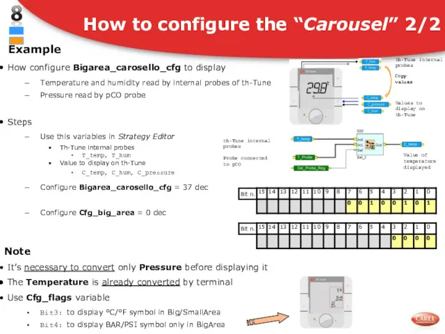
- 37. Example How configure Bigarea_carosello_cfg to display Temperature and humidity read by internal probes of th-Tune Pressure
- 38. The Big/SmallArea can show also two generic variables: the Free variables The Free variables must be
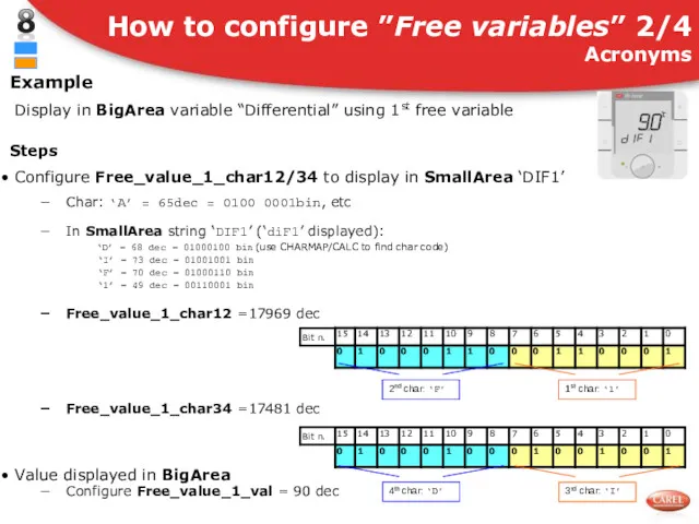
- 39. Example Display in BigArea variable “Differential” using 1st free variable Steps Configure Free_value_1_char12/34 to display in
- 40. Value displayed in BigArea Configure Free_value_1_unit to set - unit of measurement decimal point (all the
- 41. Value displayed in BigArea Configure Free_value_1_unit to set unit of measurement and decimal point Set Free_value_1_unit
- 42. It is possible to manage the icons in the lower part of the display through some
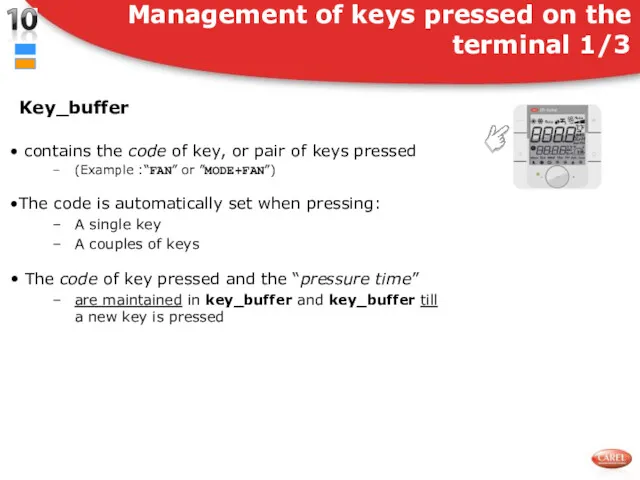
- 43. Key_buffer contains the code of key, or pair of keys pressed (Example :“FAN” or ”MODE+FAN”) The
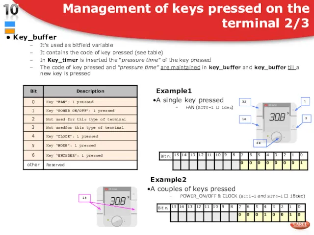
- 44. Key_buffer It’s used as bitfield variable It contains the code of key pressed (see table) In
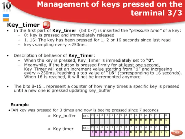
- 45. Key_timer In the first part of Key_timer (bit 0-7) is inserted the “pressure time” of a
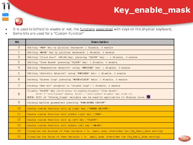
- 46. It is used to bitfield to enable or not, the functions associated with keys on the
- 47. Setting the bits in Key_enable _mask Only the functions associated with keys on the physical keyboard
- 48. It is possible to configure one or more buttons to enable a “Custom Function” The activation
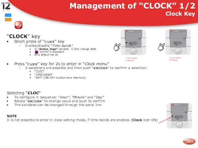
- 49. “CLOCK” key Short press of “CLOCK” key Enable/disable “Time bands” In “Status_flags” variable ? Bit1 change
- 50. Terminal can display in SmallArea Hours of the th-Tune internal clock Application can only read it
- 51. Selecting “TIME BAND” after pushing CLOCK button for 2 s After the push of “ENCODER” terminal
- 52. How to select single “Time band” From “Sel day” select “7 days” Terminal asks to select:
- 53. How to “Disable a band” In “Hour” field rotate “ENCODER” up to display “--:--” Push “ENCODER”
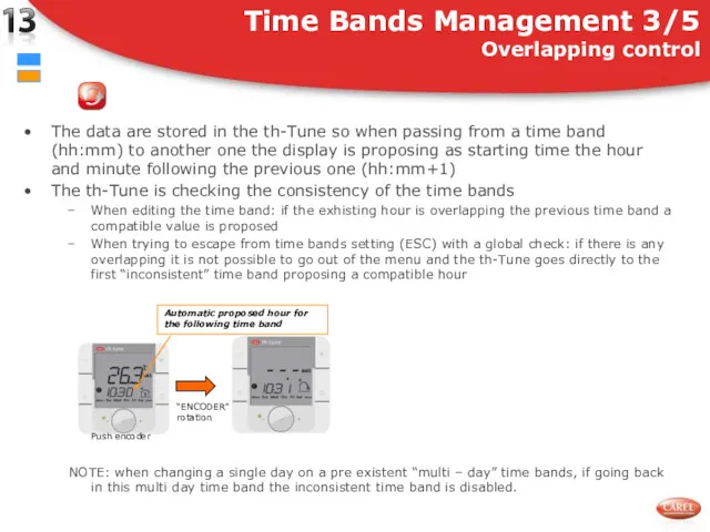
- 54. Time Bands Management 3/5 Overlapping control The data are stored in the th-Tune so when passing
- 55. When the time bands are enabled At the HH:MM of the time band Setpoint variable is
- 56. It is possible in Modbus to read and write the values for time bands used by
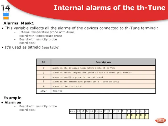
- 57. Alarms_Mask1 This variable collects all the alarms of the devices connected to th-Tune terminal: Internal temperature
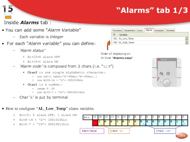
- 58. Inside Alarms tab : You can add some “Alarm Variable” Each variable is Integer For each
- 59. Diplaying “Alarms Loop” When an alarm is active “Alarm icon” is blinking Press “MODE+CLOCK ON/OFF” keys
- 60. Use Alarm_Flag variable to develop “Alarms management” Bit0: Generic alarm Bit1: Reset buzzer by user Bit2:
- 61. The Parameter tab allows to define the “Parameters” You must drag&drop variables from Variable List For
- 62. Structure of Flag variable Limitations All Flag variables must be create as T-permanent with right default
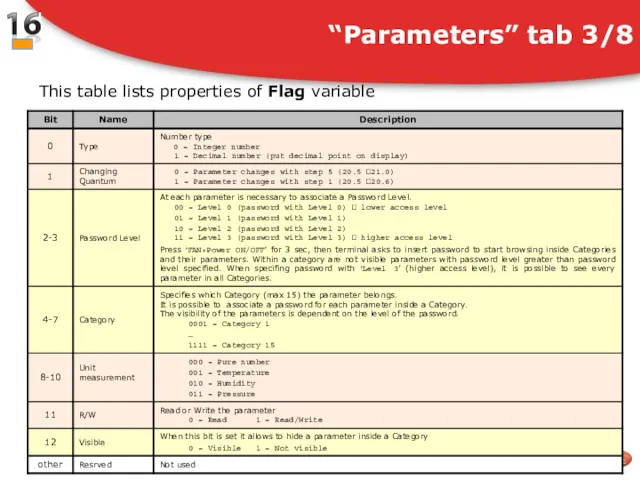
- 63. “Parameters” tab 3/8 This table lists properties of Flag variable
- 64. To create two Categories everyone with a Password and three Parameters In this example I suggest
- 65. An other way It’s to set only the right bit for each type (Menu, Password and
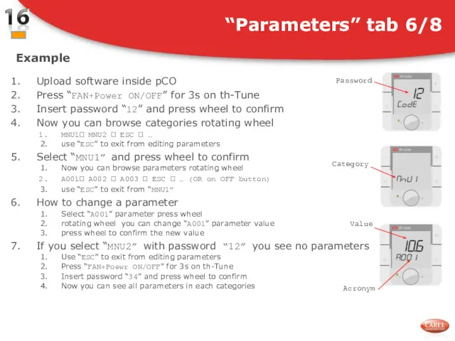
- 66. Example Upload software inside pCO Press “FAN+Power ON/OFF” for 3s on th-Tune Insert password “12” and
- 67. How add variables when row are all completed Darg&Dropp variable from Variable List where indicate by
- 68. Now setting the “read only” bit on parameters property this variable is automatically refreshed even without
- 69. This tab collects the data of the scheduler sent by the 1.0 firmware version that did
- 70. The address of the th-Tune terminal can be set in the Terminal tab or in the
- 71. How to access Terminal parameters Press ‘FAN’ e ‘Power ON/OFF’ for 3s Enter password ‘22’ NOTE
- 73. Скачать презентацию
Introduction
This presentation provides some basic explanation to develop an application
Introduction
This presentation provides some basic explanation to develop an application
Topics 1/3
Main features
Product overview, applications
Applications
Display structure and Terminal usage overview
display area,
Topics 1/3
Main features
Product overview, applications
Applications
Display structure and Terminal usage overview display area,
Topics 2/3
Terminal configuration and status variables
Main Mask variables
Icons
Key Enable Mask -
Topics 2/3
Terminal configuration and status variables
Main Mask variables
Icons
Key Enable Mask -
Topics 3/3
Internal alarms of the th-Tune
Terminal parameters
Tab Alarms
Tab Scheduler and Terminal
Topics 3/3
Internal alarms of the th-Tune
Terminal parameters
Tab Alarms
Tab Scheduler and Terminal
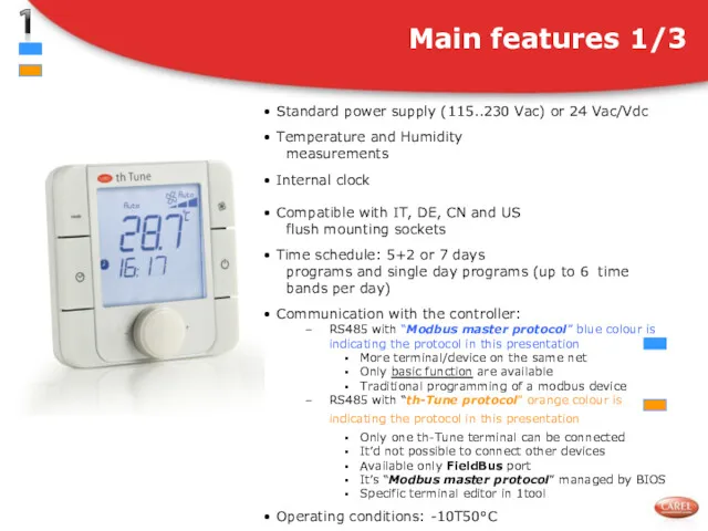
Standard power supply (115..230 Vac) or 24 Vac/Vdc
Temperature
Standard power supply (115..230 Vac) or 24 Vac/Vdc
Temperature
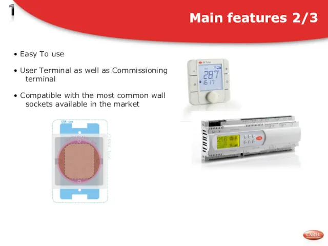
Easy To use
User Terminal as well as Commissioning
terminal
Easy To use
User Terminal as well as Commissioning
terminal
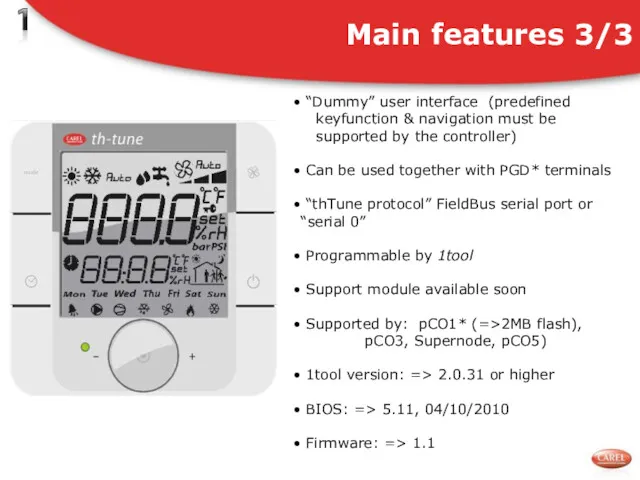
“Dummy” user interface (predefined
keyfunction & navigation must be
supported
“Dummy” user interface (predefined
keyfunction & navigation must be
supported
th-Tune Application: unit display
Advanced functions
Bringing it on the unit it’s possible
th-Tune Application: unit display
Advanced functions
Bringing it on the unit it’s possible
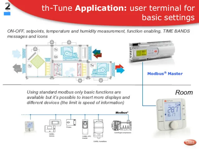
th-Tune Application: user terminal for basic settings
ON-OFF, setpoints, temperature and humidity
th-Tune Application: user terminal for basic settings
ON-OFF, setpoints, temperature and humidity
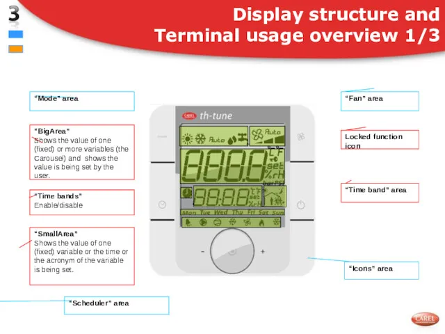
Display structure and
Terminal usage overview 1/3
“Mode” area
“Fan” area
“BigArea”
Shows the value
Display structure and
Terminal usage overview 1/3
“Mode” area
“Fan” area
“BigArea”
Shows the value
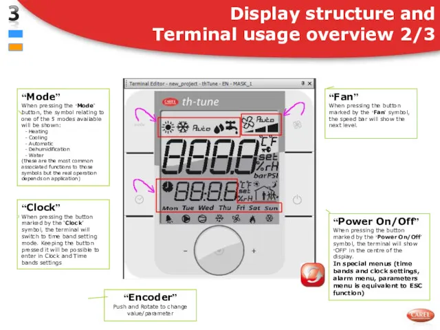
Display structure and
Terminal usage overview 2/3
“Mode”
When pressing the ‘Mode’ button,
Display structure and
Terminal usage overview 2/3
“Mode”
When pressing the ‘Mode’ button,
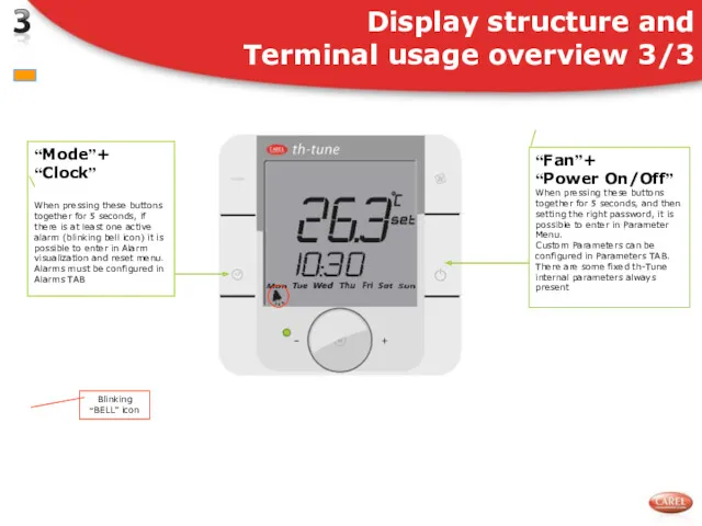
Display structure and
Terminal usage overview 3/3
“Mode”+
“Clock”
When pressing these buttons together
Display structure and
Terminal usage overview 3/3
“Mode”+
“Clock”
When pressing these buttons together
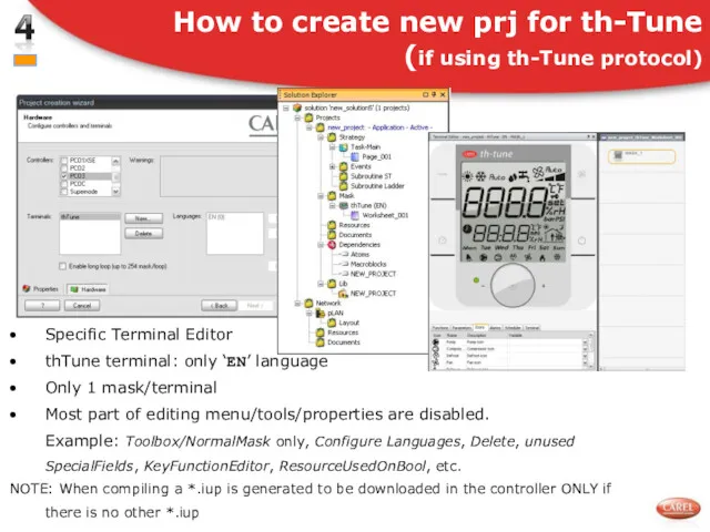
Specific Terminal Editor
thTune terminal: only ‘EN’ language
Only 1 mask/terminal
Most part
Specific Terminal Editor
thTune terminal: only ‘EN’ language
Only 1 mask/terminal
Most part
Check list of variables available in Modbus
Use de Modbus master DEMO
Check list of variables available in Modbus
Use de Modbus master DEMO
Terminal Editor components
and Editing 1/2
Terminal Editor components
and Editing 1/2
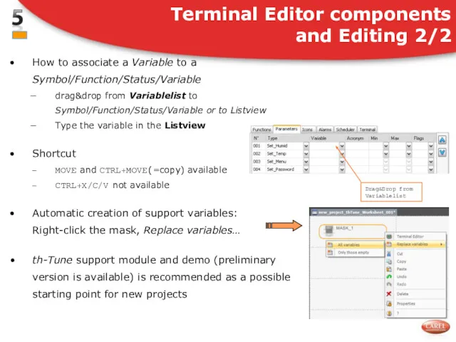
How to associate a Variable to a Symbol/Function/Status/Variable
drag&drop from Variablelist to
drag&drop from Variablelist to
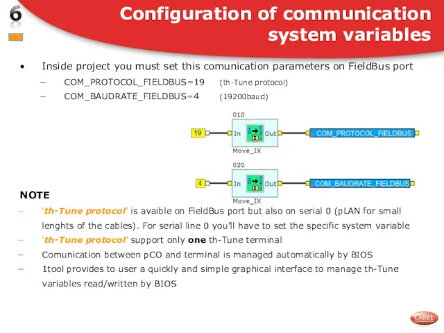
Inside project you must set this comunication parameters on FieldBus port
COM_PROTOCOL_FIELDBUS=19
Inside project you must set this comunication parameters on FieldBus port
COM_PROTOCOL_FIELDBUS=19
Make sure that baudrate and address on the th-Tune are correct:
Make sure that baudrate and address on the th-Tune are correct:
There are some variables indicating the status and the configuration of
There are some variables indicating the status and the configuration of
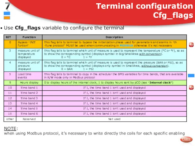
Use Cfg_flags variable to configure the terminal
Terminal configuration
Cfg_flags
NOTE:
when using
Use Cfg_flags variable to configure the terminal
Terminal configuration
Cfg_flags
NOTE:
when using
Status_flags variable
status register of the terminal used to provide general information.
status register of the terminal used to provide general information.
How to use Cfg_flags variable
Bit3= 1 to display °F symbol
How to use Cfg_flags variable
Bit3= 1 to display °F symbol
New management at the power on of th-Tune
At the power
New management at the power on of th-Tune
At the power
How to manage th-Tune display state:
Use “Power ON/OFF” button manage state
How to manage th-Tune display state:
Use “Power ON/OFF” button manage state
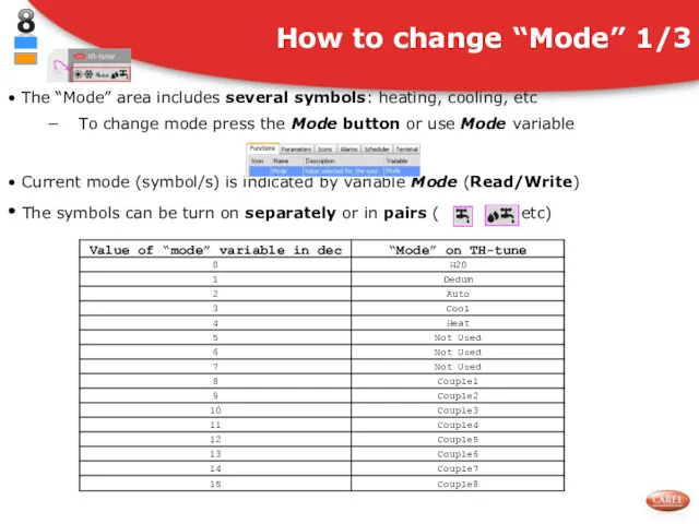
The “Mode” area includes several symbols: heating, cooling, etc
To
The “Mode” area includes several symbols: heating, cooling, etc
To
Example
The symbols (and pairs) must be configured before being used with
The symbols (and pairs) must be configured before being used with
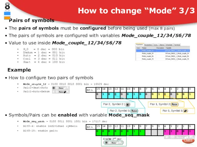
Pairs of symbols
The pairs of symbols must be configured
Pairs of symbols
The pairs of symbols must be configured
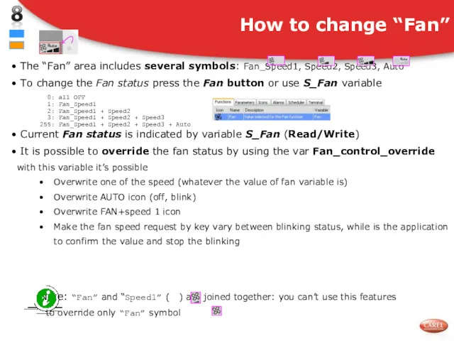
The “Fan” area includes several symbols: Fan_Speed1, Speed2, Speed3, Auto
To
To
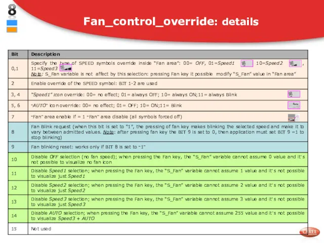
Fan_control_override: details
Fan_control_override: details
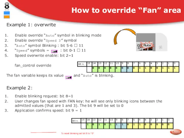
How to override “Fan” area
Example 1: overwrite
Enable override “Auto” symbol
How to override “Fan” area
Example 1: overwrite
Enable override “Auto” symbol
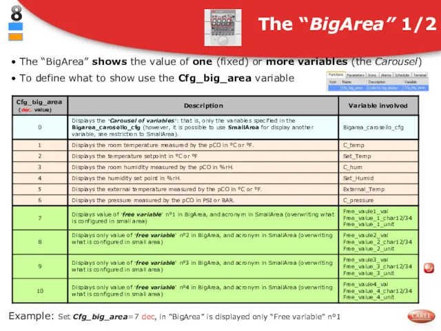
The “BigArea” shows the value of one (fixed) or more
The “BigArea” shows the value of one (fixed) or more
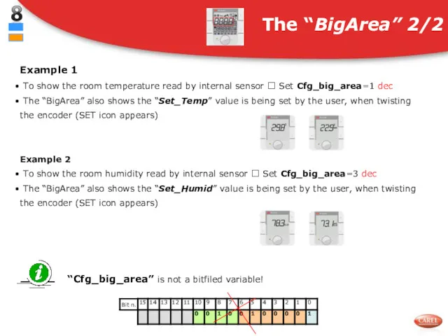
Example 1
To show the room temperature read by internal sensor
Example 1
To show the room temperature read by internal sensor
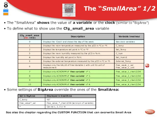
The “SmallArea” shows the value of a variable or the clock
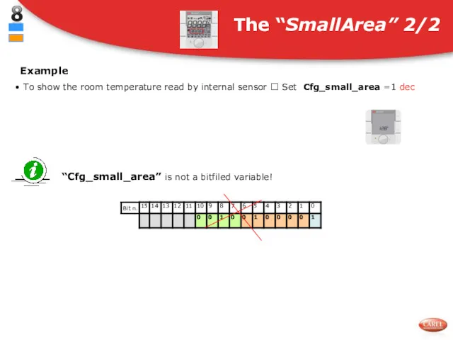
Example
To show the room temperature read by internal sensor ?
Example
To show the room temperature read by internal sensor ?
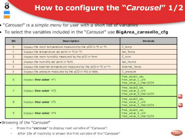
“Carousel” is a simple menu for user with a short list
Example
How configure Bigarea_carosello_cfg to display
Temperature and humidity read by
Example
How configure Bigarea_carosello_cfg to display
Temperature and humidity read by
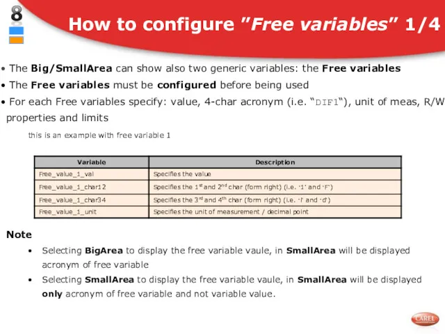
The Big/SmallArea can show also two generic variables: the Free variables
Example
Display in BigArea variable “Differential” using 1st free variable
Steps
Configure
Example
Display in BigArea variable “Differential” using 1st free variable
Steps
Configure
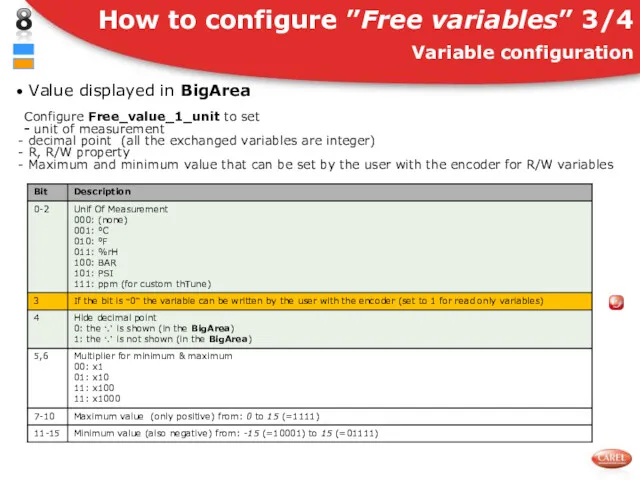
Value displayed in BigArea
Configure Free_value_1_unit to set
- unit of
Configure Free_value_1_unit to set
- unit of
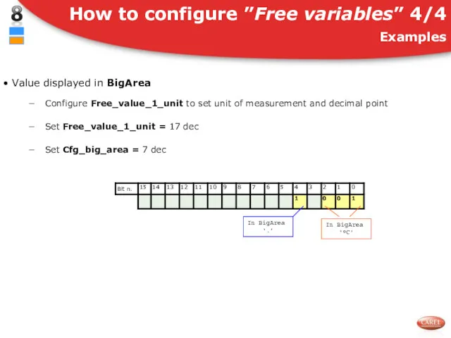
Value displayed in BigArea
Configure Free_value_1_unit to set unit of measurement
Configure Free_value_1_unit to set unit of measurement
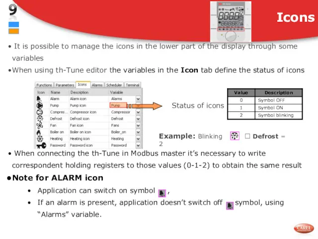
It is possible to manage the icons in the lower part
Key_buffer
contains the code of key, or pair of keys pressed
(Example :“FAN”
Key_buffer
contains the code of key, or pair of keys pressed
(Example :“FAN”
Key_buffer
It’s used as bitfield variable
It contains the code of key
Key_buffer
It’s used as bitfield variable
It contains the code of key
Key_timer
In the first part of Key_timer (bit 0-7) is inserted the
Key_timer
In the first part of Key_timer (bit 0-7) is inserted the
It is used to bitfield to enable or not, the functions
It is used to bitfield to enable or not, the functions
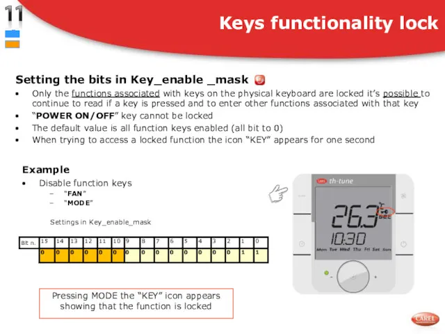
Setting the bits in Key_enable _mask
Only the functions associated with keys
Setting the bits in Key_enable _mask
Only the functions associated with keys
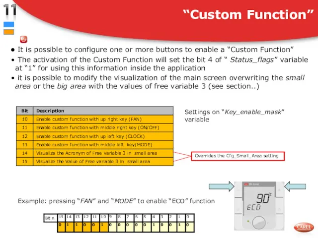
It is possible to configure one or more buttons to
It is possible to configure one or more buttons to
“CLOCK” key
Short press of “CLOCK” key
Enable/disable “Time bands”
In “Status_flags” variable
“CLOCK” key
Short press of “CLOCK” key
Enable/disable “Time bands”
In “Status_flags” variable
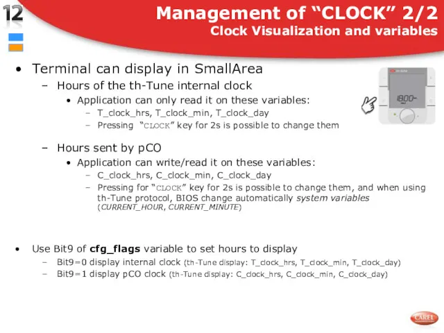
Terminal can display in SmallArea
Hours of the th-Tune internal clock
Application can
Terminal can display in SmallArea
Hours of the th-Tune internal clock
Application can
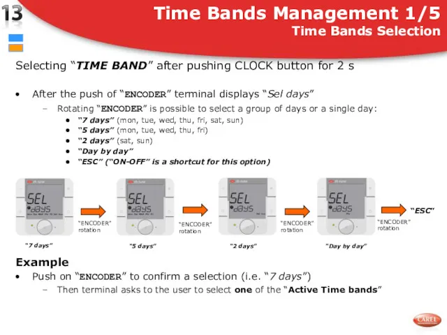
Selecting “TIME BAND” after pushing CLOCK button for 2 s
After the
Selecting “TIME BAND” after pushing CLOCK button for 2 s
After the
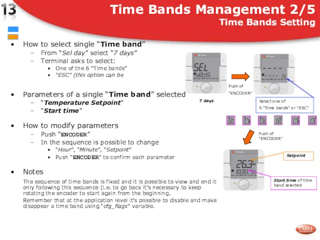
How to select single “Time band”
From “Sel day” select “7
How to select single “Time band”
From “Sel day” select “7
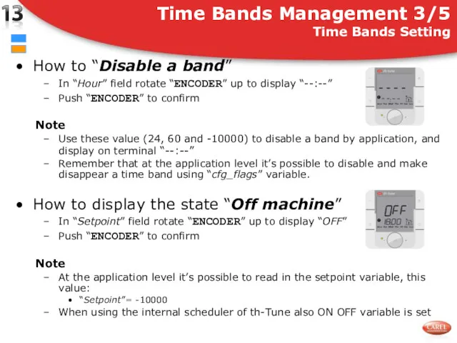
How to “Disable a band”
In “Hour” field rotate “ENCODER” up to
How to “Disable a band”
In “Hour” field rotate “ENCODER” up to
Time Bands Management 3/5
Overlapping control
The data are stored in the th-Tune
Time Bands Management 3/5
Overlapping control
The data are stored in the th-Tune
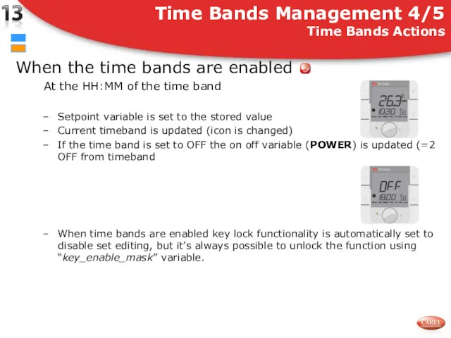
When the time bands are enabled
At the HH:MM of the time
When the time bands are enabled
At the HH:MM of the time
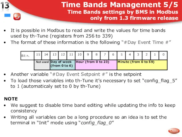
It is possible in Modbus to read and write the values
It is possible in Modbus to read and write the values
Alarms_Mask1
This variable collects all the alarms of the devices connected
Alarms_Mask1
This variable collects all the alarms of the devices connected
Inside Alarms tab :
You can add some “Alarm Variable”
Inside Alarms tab :
You can add some “Alarm Variable”
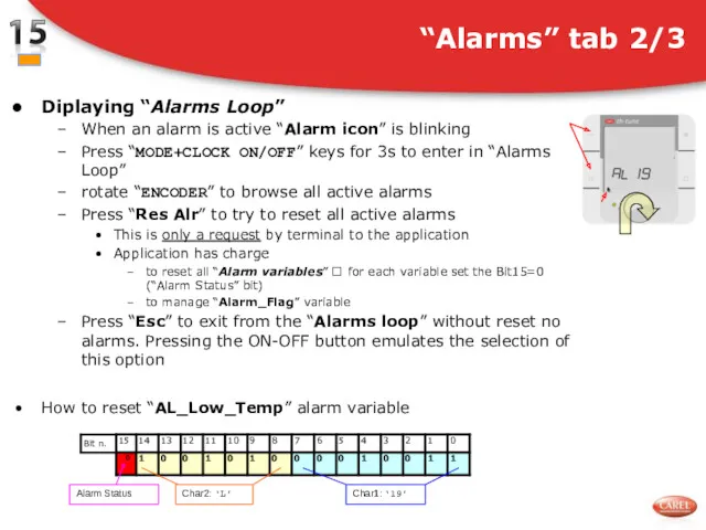
Diplaying “Alarms Loop”
When an alarm is active “Alarm icon” is blinking
Press
Diplaying “Alarms Loop”
When an alarm is active “Alarm icon” is blinking
Press
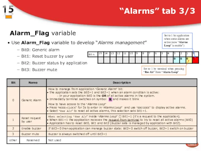
Use Alarm_Flag variable to develop “Alarms management”
Bit0: Generic alarm
Use Alarm_Flag variable to develop “Alarms management”
Bit0: Generic alarm
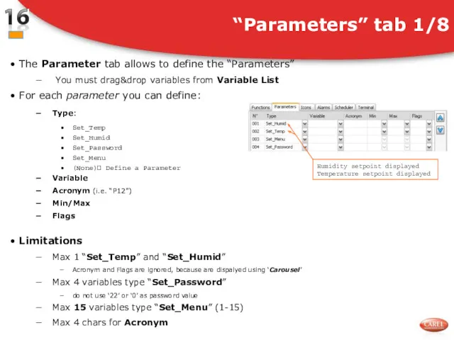
The Parameter tab allows to define the “Parameters”
You
The Parameter tab allows to define the “Parameters”
You
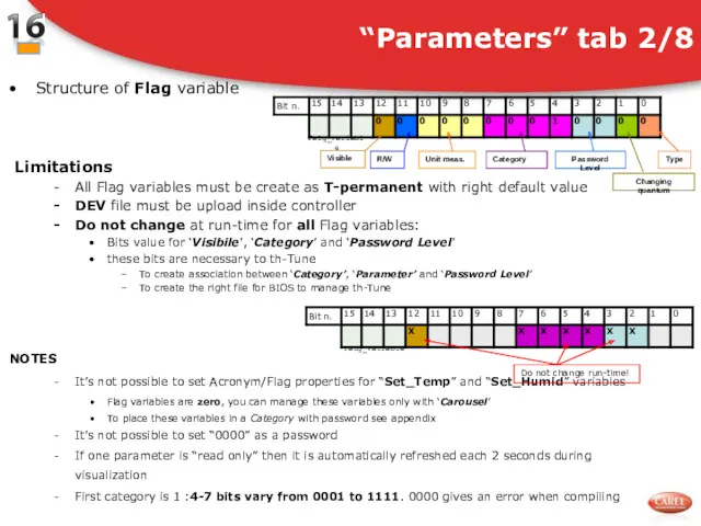
Structure of Flag variable
Limitations
All Flag variables must be create as T-permanent
Structure of Flag variable
Limitations
All Flag variables must be create as T-permanent
“Parameters” tab 3/8
This table lists properties of Flag variable
“Parameters” tab 3/8
This table lists properties of Flag variable
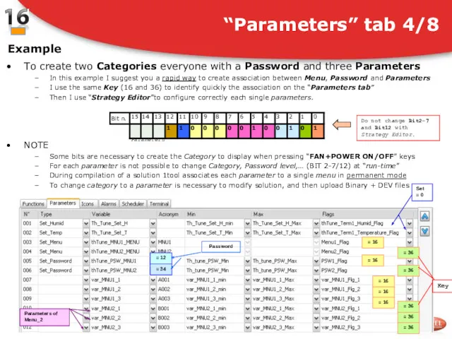
To create two Categories everyone with a Password and three Parameters
In
To create two Categories everyone with a Password and three Parameters
In
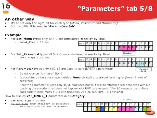
An other way
It’s to set only the right bit for each
An other way
It’s to set only the right bit for each
Example
Upload software inside pCO
Press “FAN+Power ON/OFF” for 3s on th-Tune
Insert password
Example
Upload software inside pCO
Press “FAN+Power ON/OFF” for 3s on th-Tune
Insert password
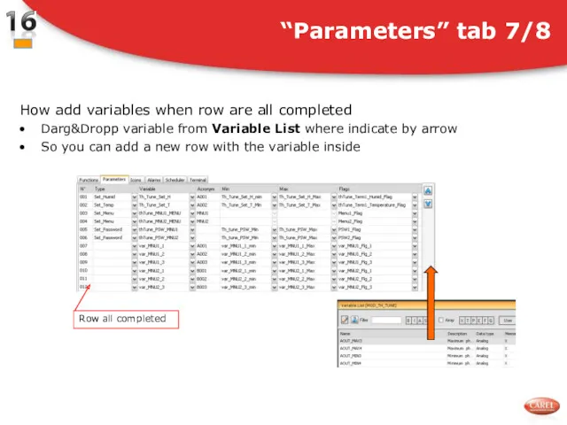
How add variables when row are all completed
Darg&Dropp variable from
How add variables when row are all completed
Darg&Dropp variable from
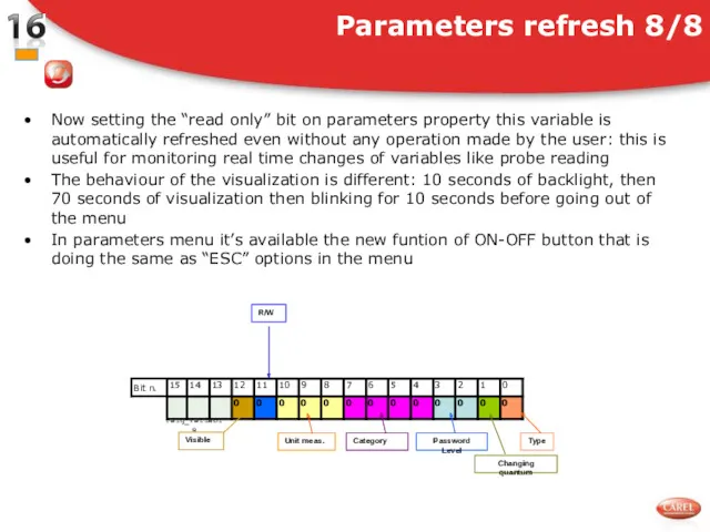
Now setting the “read only” bit on parameters property this variable
Now setting the “read only” bit on parameters property this variable
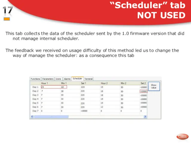
This tab collects the data of the scheduler sent by the
This tab collects the data of the scheduler sent by the
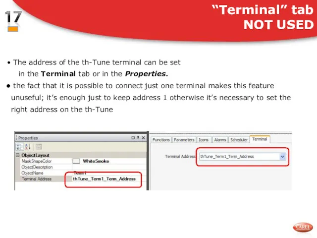
The address of the th-Tune terminal can be set in
The address of the th-Tune terminal can be set in
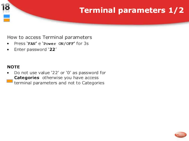
How to access Terminal parameters
Press ‘FAN’ e ‘Power ON/OFF’ for 3s
Enter
How to access Terminal parameters
Press ‘FAN’ e ‘Power ON/OFF’ for 3s
Enter
 Степени сравнения прилагательных. Adjectives. Degrees of Comparison
 Tongue twisters
 What’s new in C# 7
 State Transition Testing Technique Training
 Как написать письмо
 What are you going to do during your holidays?
 Артикли – особые (служебные) частицы, употребляемые при именах существительных
 Страна Шотландия
 Spotlight 2 кл
 Spring
 Trick or treat?
 Direct and indirect (reported) speech
 Staff of a restaurant
 The United Kingdom of Great Britain and Northern Ireland - Соединенное королевство Великобритании и Северной Ирландии
 цвета 27.01
 Притяжательные местоимения
 Simple past tense. Affirmative and negative form
 Enjoy English 4. Unit 2. Enjoying your home
 Present simple
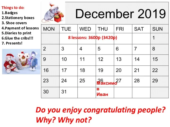 Do you enjoy congratulating people?
 Great Britain
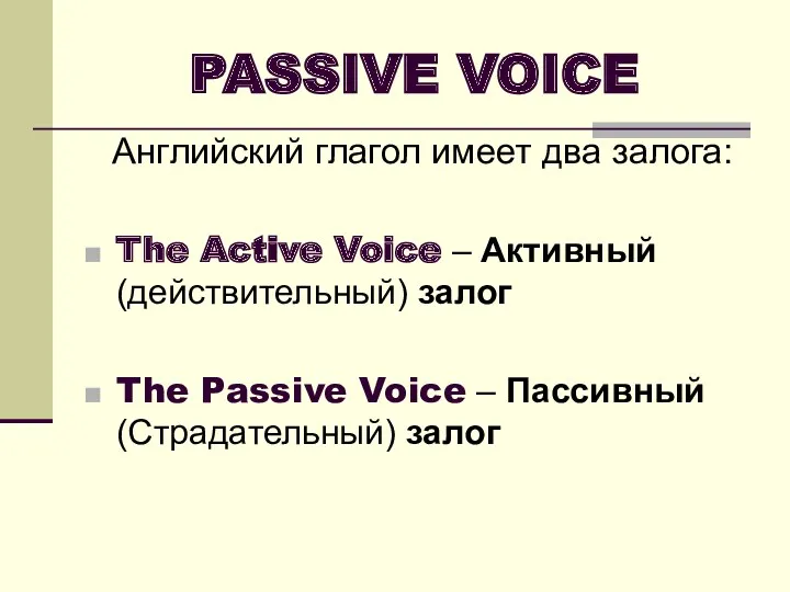 Passive voice
 Virtual reality
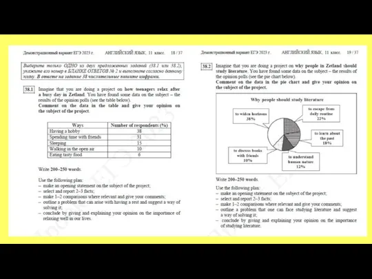 Эссе. Задание 38
 Australia is a fascinating country
 Итоги муниципального этапа ВcОШ по английскому языку 2014 - 2015 учебного года
 The Present Simple Tense
 Present Tenses