- Introduction. Waste management

Содержание
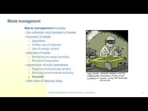
- 2. Waste management Waste management includes the collection and transport of waste recovery of waste Separation Further
- 3. Waste Policy in Finland Is in line with the EU waste policy Sets the wider perspective
- 4. The 4 R concept The 4R concept Included in the Finnish Waste policy Reduce Reuse Recycle
- 5. Practising the 4 R concept Reducing waste requires activities in the whole product chain and planning
- 6. Lecture 2: Collection and transport
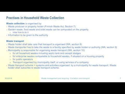
- 7. 8.9.2016 Waste management and recycling - Collection and transport Practises in Household Waste Collection Waste collection
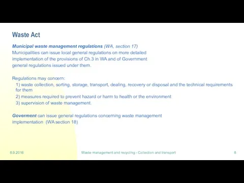
- 8. 8.9.2016 Waste management and recycling - Collection and transport Waste Act Municipal waste management regulations (WA,
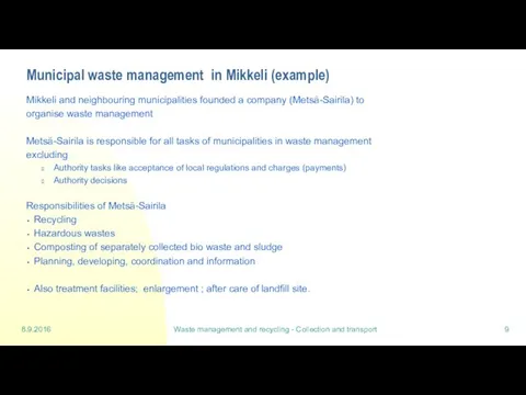
- 9. 8.9.2016 Waste management and recycling - Collection and transport Municipal waste management in Mikkeli (example) Mikkeli
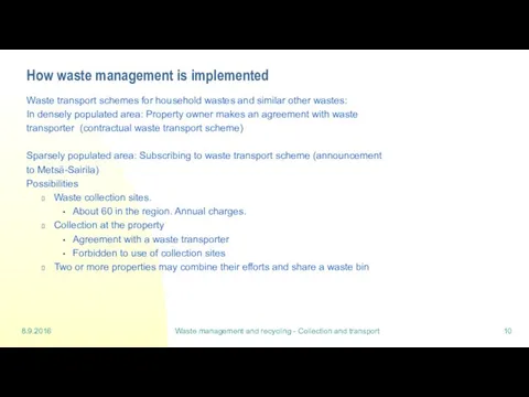
- 10. 8.9.2016 Waste management and recycling - Collection and transport How waste management is implemented Waste transport
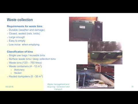
- 11. 8.9.2016 Waste management and recycling - Collection and transport Waste collection Requirements for waste bins: Durable
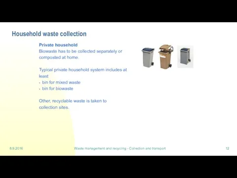
- 12. 8.9.2016 Waste management and recycling - Collection and transport Household waste collection Private household Biowaste has
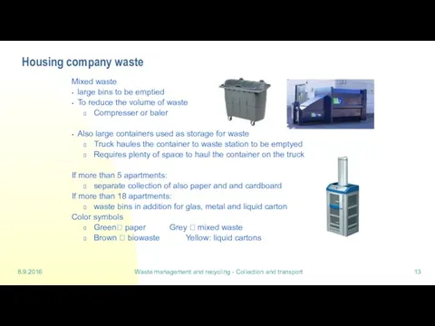
- 13. 8.9.2016 Waste management and recycling - Collection and transport Housing company waste Mixed waste large bins
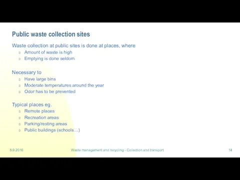
- 14. 8.9.2016 Waste management and recycling - Collection and transport Public waste collection sites Waste collection at
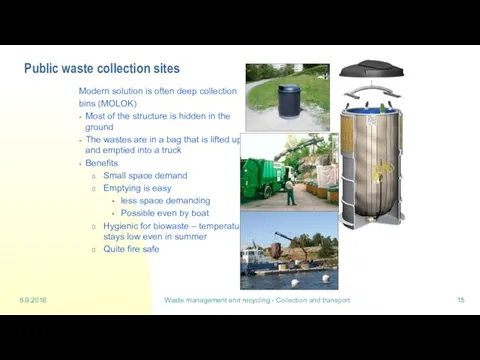
- 15. 8.9.2016 Waste management and recycling - Collection and transport Public waste collection sites Modern solution is
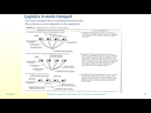
- 16. 8.9.2016 Waste management and recycling - Collection and transport Logistics in waste transport The waste transport
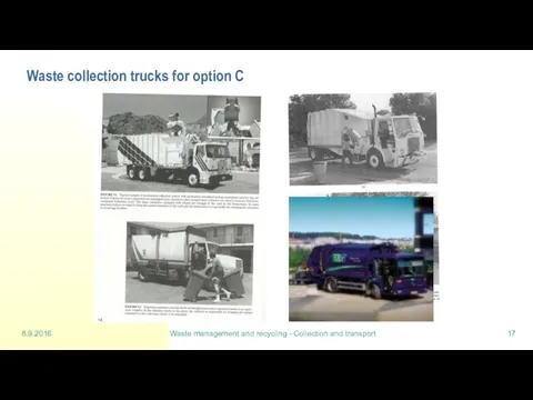
- 17. 8.9.2016 Waste management and recycling - Collection and transport Waste collection trucks for option C
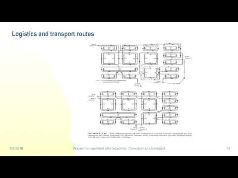
- 18. 8.9.2016 Waste management and recycling - Collection and transport Logistics and transport routes
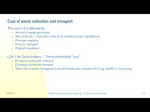
- 19. 8.9.2016 Waste management and recycling - Collection and transport Cost of waste collection and transport The
- 20. Lecture 3: Waste sorting
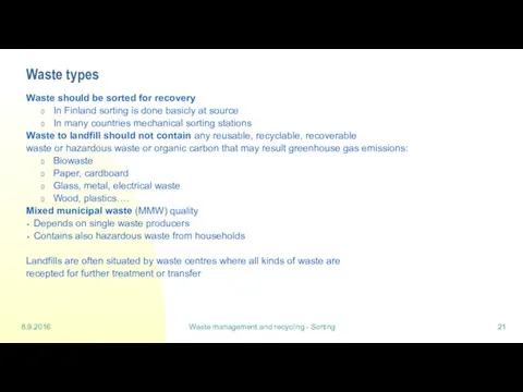
- 21. 8.9.2016 Waste management and recycling - Sorting Waste types Waste should be sorted for recovery In
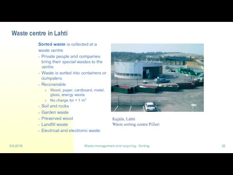
- 22. 8.9.2016 Waste management and recycling - Sorting Waste centre in Lahti Sorted waste is collected at
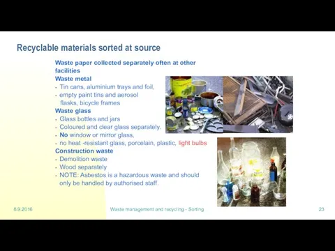
- 23. 8.9.2016 Waste management and recycling - Sorting Recyclable materials sorted at source Waste paper collected separately
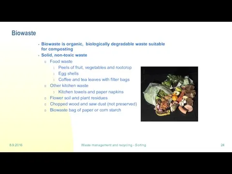
- 24. 8.9.2016 Waste management and recycling - Sorting Biowaste Biowaste is organic, biologically degradable waste suitable for
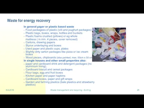
- 25. 8.9.2016 Waste management and recycling - Sorting Waste for energy recovery In general paper or plastic
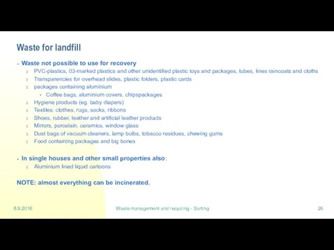
- 26. 8.9.2016 Waste management and recycling - Sorting Waste for landfill Waste not possible to use for
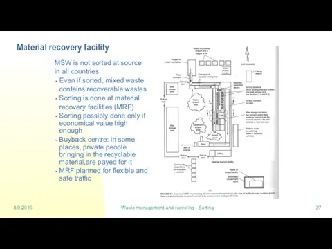
- 27. 8.9.2016 Waste management and recycling - Sorting Material recovery facility MSW is not sorted at source
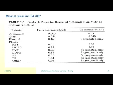
- 28. 8.9.2016 Waste management and recycling - Sorting Material prices in USA 2002
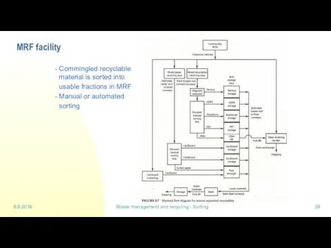
- 29. 8.9.2016 Waste management and recycling - Sorting MRF facility Commingled recyclable material is sorted into usable
- 30. 8.9.2016 Waste management and recycling - Sorting Processing of and recovery from mixed municipal waste Manual
- 31. 8.9.2016 Waste management and recycling - Sorting Main steps in material classification
- 32. 8.9.2016 Waste management and recycling - Sorting Size Reduction
- 33. 8.9.2016 Waste management and recycling - Sorting Size separation
- 34. 8.9.2016 Waste management and recycling - Sorting Size separation
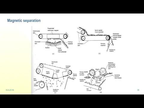
- 35. 8.9.2016 Waste management and recycling - Sorting Magnetic separation
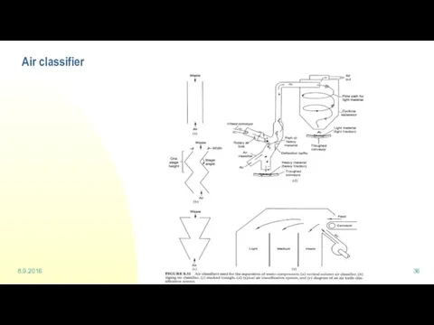
- 36. 8.9.2016 Waste management and recycling - Sorting Air classifier
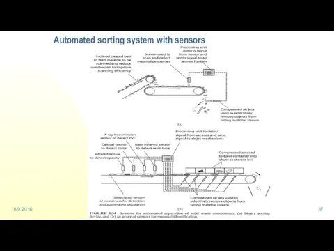
- 37. 8.9.2016 Waste management and recycling - Sorting Automated sorting system with sensors
- 38. Lecture 4: Landfill
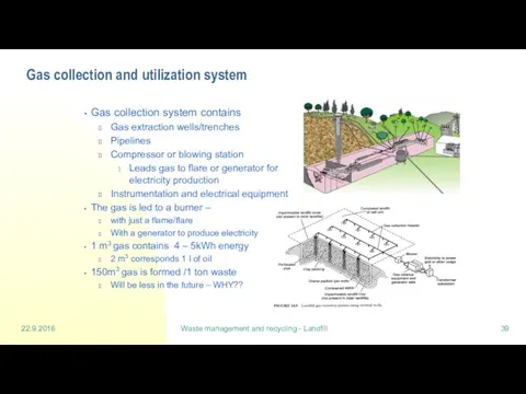
- 39. 22.9.2016 Waste management and recycling - Landfill Gas collection and utilization system Gas collection system contains
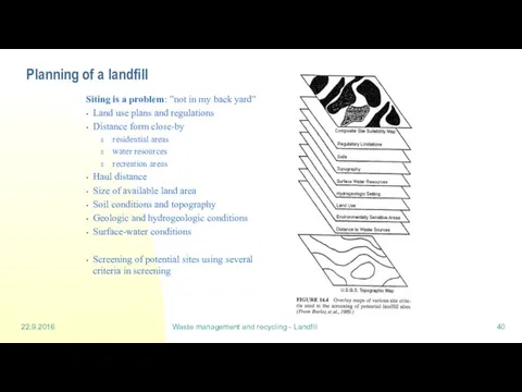
- 40. 22.9.2016 Waste management and recycling - Landfill Planning of a landfill Siting is a problem: ”not
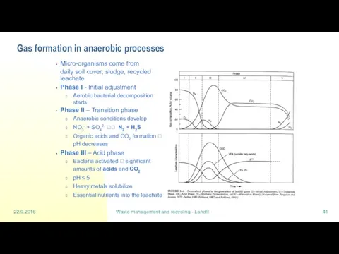
- 41. 22.9.2016 Waste management and recycling - Landfill Gas formation in anaerobic processes Micro-organisms come from daily
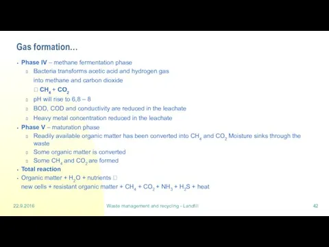
- 42. 22.9.2016 Waste management and recycling - Landfill Gas formation… Phase IV – methane fermentation phase Bacteria
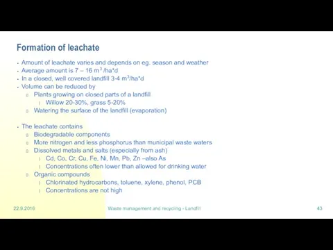
- 43. 22.9.2016 Waste management and recycling - Landfill Formation of leachate Amount of leachate varies and depends
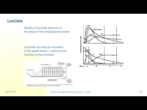
- 44. 22.9.2016 Waste management and recycling - Landfill Leachate Quality of leachate depends on the phase of
- 45. 22.9.2016 Waste management and recycling - Landfill Construction of a landfill before filling it The landfill
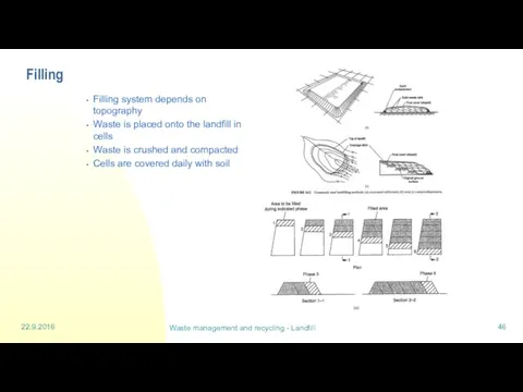
- 46. 22.9.2016 Waste management and recycling - Landfill Filling Filling system depends on topography Waste is placed
- 47. 22.9.2016 Waste management and recycling - Landfill Waste layers in a landfill a) Bottom layers are
- 48. 22.9.2016 Waste management and recycling - Landfill Landfill Bottom Structure Soil quality is important Structure contains
- 49. 22.9.2016 Waste management and recycling - Landfill Landfill bottom structure Waste fill Drainage Traffic layer Filter
- 50. 22.9.2016 Waste management and recycling - Landfill Required bottom layers Bottom layers Base soil has to
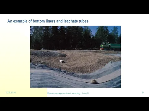
- 51. 22.9.2016 Waste management and recycling - Landfill An example of bottom liners and leachate tubes
- 52. Lecture 5: Composting (part 1)
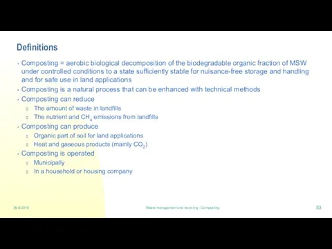
- 53. 29.9.2016 Waste management and recycling - Composting Definitions Composting = aerobic biological decomposition of the biodegradable
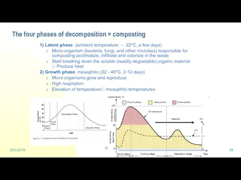
- 54. 29.9.2016 Waste management and recycling - Composting The four phases of decomposition = composting 1) Latent
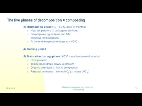
- 55. 29.9.2016 Waste management and recycling - Composting The five phases of decomposition = composting 3) Thermophilic
- 56. 29.9.2016 Waste management and recycling - Composting Factors affecting the decomposition in the compost Temperature Depends
- 57. 29.9.2016 Waste management and recycling - Composting Factors affecting the decomposition in the compost Particle size
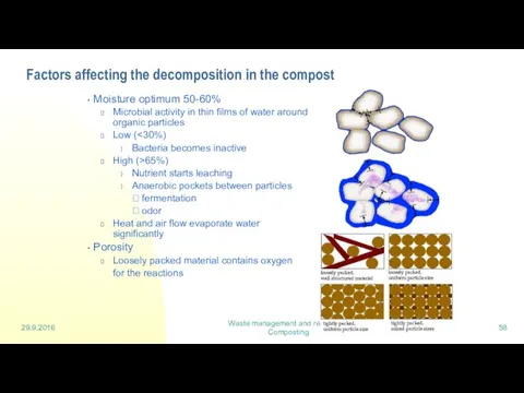
- 58. 29.9.2016 Waste management and recycling - Composting Factors affecting the decomposition in the compost Moisture optimum
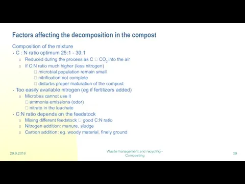
- 59. 29.9.2016 Waste management and recycling - Composting Factors affecting the decomposition in the compost Composition of
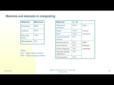
- 60. 29.9.2016 Waste management and recycling - Composting Materials and elements in composting Often Dry = high
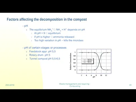
- 61. 29.9.2016 Waste management and recycling - Composting Factors affecting the decomposition in the compost pH The
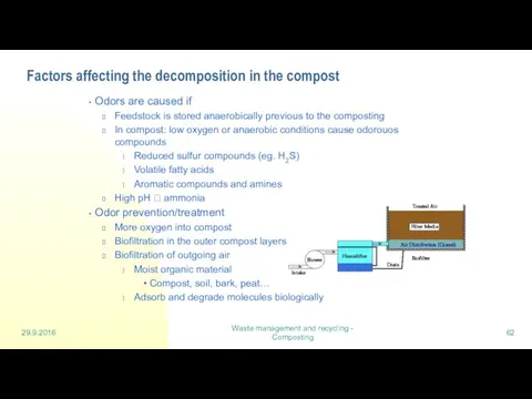
- 62. 29.9.2016 Waste management and recycling - Composting Factors affecting the decomposition in the compost Odors are
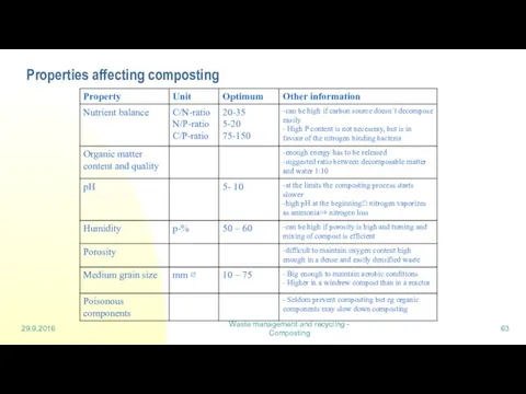
- 63. 29.9.2016 Waste management and recycling - Composting Properties affecting composting Taulukko 3.1 Jätteen ominaisuuksien optimiarvoja. (Lilja
- 64. Lecture 6: Digestion
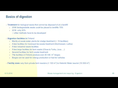
- 65. 6.10.2016 Waste management and recycling - Digestion Basics of digestion Treatment for biological waste that cannot
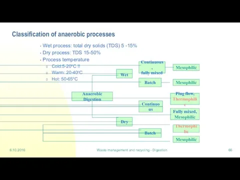
- 66. 6.10.2016 Waste management and recycling - Digestion Classification of anaerobic processes Wet process: total dry solids
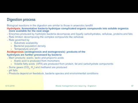
- 67. 6.10.2016 Waste management and recycling - Digestion Digestion process Biological reactions in the digestion are similar
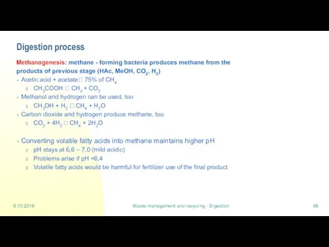
- 68. 6.10.2016 Waste management and recycling - Digestion Digestion process Methanogenesis: methane - forming bacteria produces methane
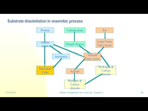
- 69. 6.10.2016 Waste management and recycling - Digestion Substrate dissimilation in anaerobic process Protein Carbohydrate Fat Long
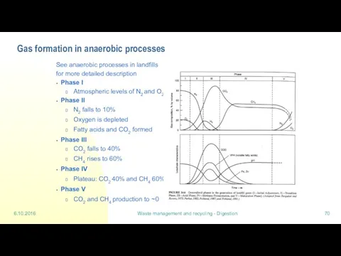
- 70. 6.10.2016 Waste management and recycling - Digestion Gas formation in anaerobic processes See anaerobic processes in
- 71. Lecture 7: Waste incineration (part 2)
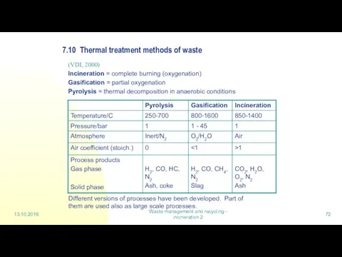
- 72. 13.10.2016 Waste management and recycling - incineration 2 7.10 Thermal treatment methods of waste (VDI, 2000)
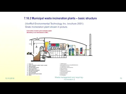
- 73. 13.10.2016 Waste management and recycling - incineration 2 7.10.2 Municipal waste incineration plants – basic structure
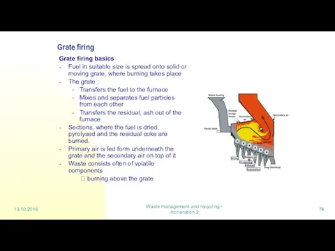
- 74. 13.10.2016 Waste management and recycling - incineration 2 Grate firing Grate firing basics Fuel in suitable
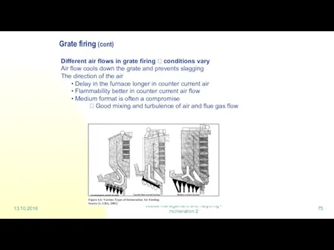
- 75. 13.10.2016 Waste management and recycling - incineration 2 Grate firing (cont) Different air flows in grate
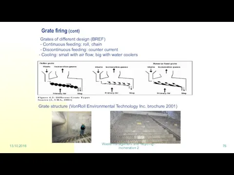
- 76. 13.10.2016 Waste management and recycling - incineration 2 Grate firing (cont) Grate structure (VonRoll Environmental Technology
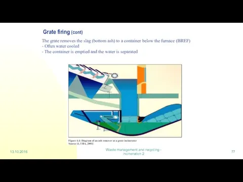
- 77. 13.10.2016 Waste management and recycling - incineration 2 Grate firing (cont) The grate removes the slag
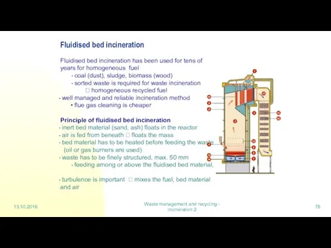
- 78. 13.10.2016 Waste management and recycling - incineration 2 Fluidised bed incineration Fluidised bed incineration has been
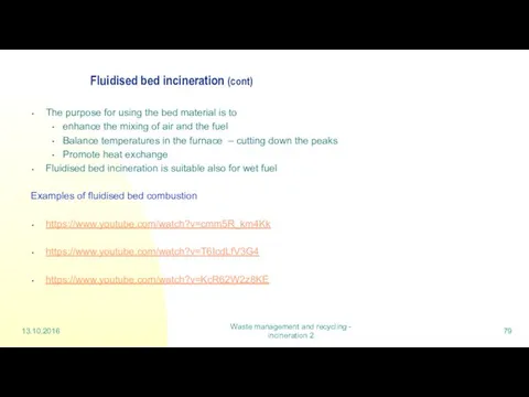
- 79. 13.10.2016 Waste management and recycling - incineration 2 Fluidised bed incineration (cont) The purpose for using
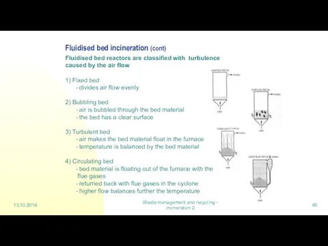
- 80. 13.10.2016 Waste management and recycling - incineration 2 Fluidised bed incineration (cont) Fluidised bed reactors are
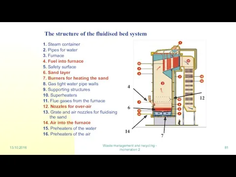
- 81. 13.10.2016 Waste management and recycling - incineration 2 The structure of the fluidised bed system 1.
- 82. 13.10.2016 Waste management and recycling - incineration 2 Fluidised bed techniques Common The bed material has
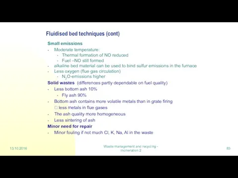
- 83. 13.10.2016 Waste management and recycling - incineration 2 Fluidised bed techniques (cont) Small emissions Moderate temperature:
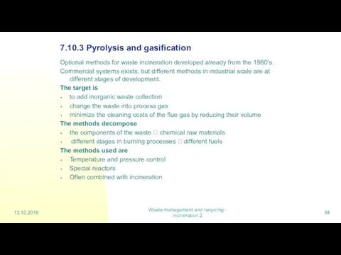
- 84. 13.10.2016 Waste management and recycling - incineration 2 7.10.3 Pyrolysis and gasification Optional methods for waste
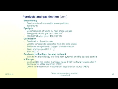
- 85. 13.10.2016 Waste management and recycling - incineration 2 Pyrolysis and gasification (cont) Smouldering Gas formation from
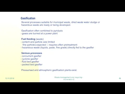
- 86. 13.10.2016 Waste management and recycling - incineration 2 Gasification Several processes suitable for municipal waste, dried
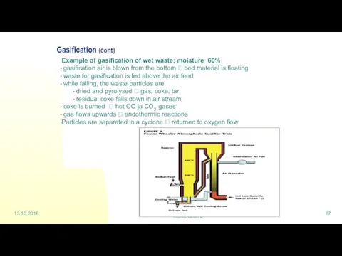
- 87. 13.10.2016 Waste management and recycling - incineration 2 Gasification (cont) Example of gasification of wet waste;
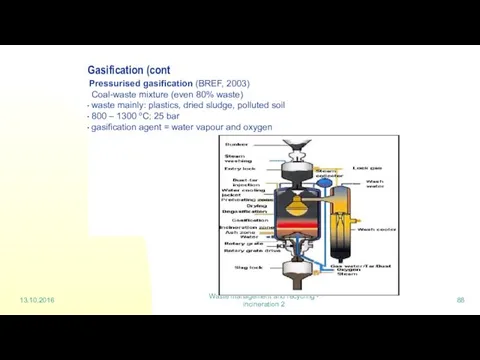
- 88. 13.10.2016 Waste management and recycling - incineration 2 Gasification (cont Pressurised gasification (BREF, 2003) Coal-waste mixture
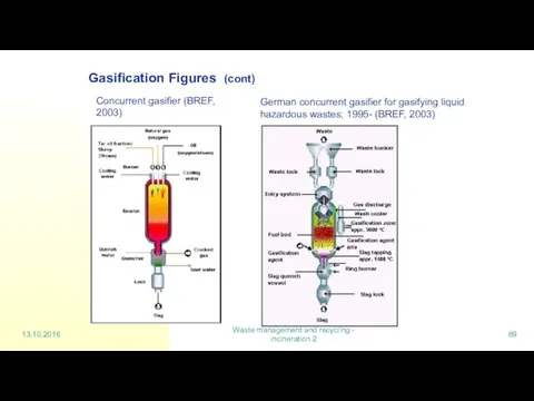
- 89. 13.10.2016 Waste management and recycling - incineration 2 Gasification Figures (cont) Concurrent gasifier (BREF, 2003) German
- 90. 13.10.2016 Waste management and recycling - incineration 2 Gasification (cont) Benefits gasification enables also low quality,
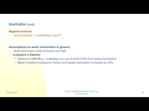
- 91. 13.10.2016 Waste management and recycling - incineration 2 Gasification (cont) Negative features new processes ? uncertainty
- 92. Lecture 8: Hazardous waste
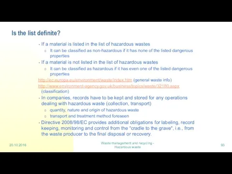
- 93. 20.10.2016 Waste management and recycling - Hazardous waste Is the list definite? If a material is
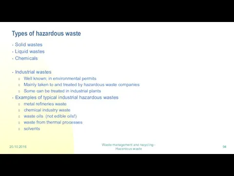
- 94. Types of hazardous waste Solid wastes Liquid wastes Chemicals Industrial wastes Well known; in environmental permits
- 95. Treatment, main aspects Sorted and labelled waste Waste to energy Thermal treatment Physico-chemical treatment Biological treatment
- 96. 1 High temperature incineration Process units at Ekokem The core unit is a 12-metre rotary kiln
- 97. High temperature incineration of hazardous waste 20.10.2016 Waste management and recycling - Hazardous waste Water treatment
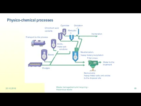
- 98. 4 Physico- chemical processes Inorganic wastes, such as acids, bases and heavy metal containing liquids are
- 99. Physico-chemical processes 20.10.2016 Waste management and recycling - Hazardous waste Non-soluble heavy metal salts and oxides
- 100. Lecture 9: Life cycle assessment
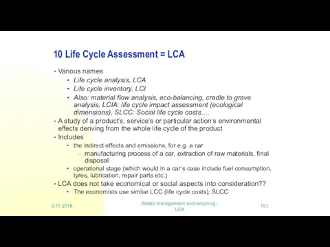
- 101. Waste management and recycling - LCA 10 Life Cycle Assessment = LCA Various names Life cycle
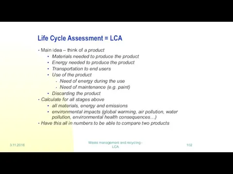
- 102. Waste management and recycling - LCA Life Cycle Assessment = LCA Main idea – think of
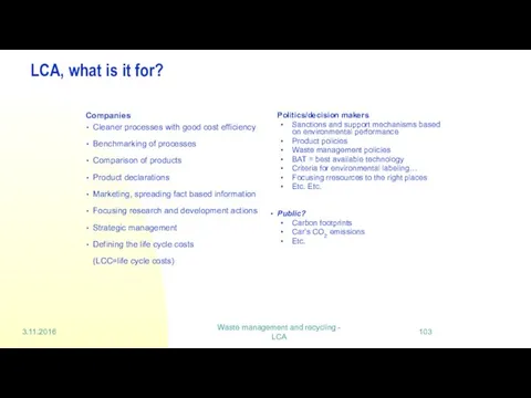
- 103. Waste management and recycling - LCA LCA, what is it for? Companies Cleaner processes with good
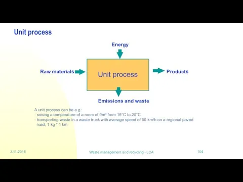
- 104. Waste management and recycling - LCA Unit process A unit process can be e.g.: - raising
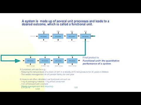
- 105. Waste management and recycling - LCA A system is made up of several unit processes and
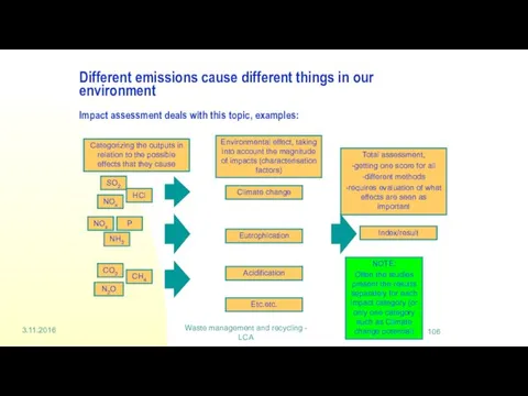
- 106. Waste management and recycling - LCA Different emissions cause different things in our environment Impact assessment
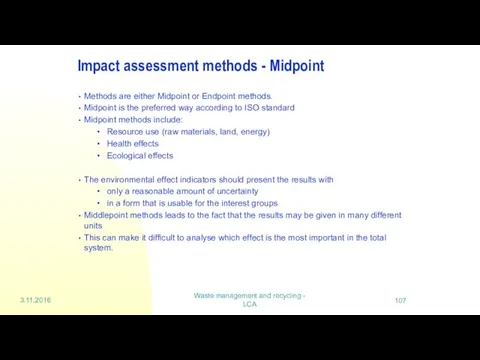
- 107. Waste management and recycling - LCA Impact assessment methods - Midpoint Methods are either Midpoint or
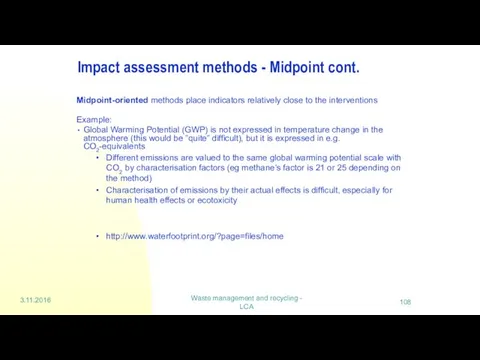
- 108. Waste management and recycling - LCA Impact assessment methods - Midpoint cont. Midpoint-oriented methods place indicators
- 110. Скачать презентацию
Waste management
Waste management includes
the collection and transport of waste
recovery of
Waste management
Waste management includes
the collection and transport of waste
recovery of
Waste Policy in Finland
Is in line with the EU waste policy
Sets
Waste Policy in Finland
Is in line with the EU waste policy
Sets
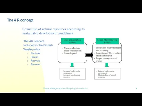
The 4 R concept
The 4R concept
Included in the Finnish
Waste policy
Reduce
Reuse
Recycle
The 4 R concept
The 4R concept
Included in the Finnish
Waste policy
Reduce
Reuse
Recycle
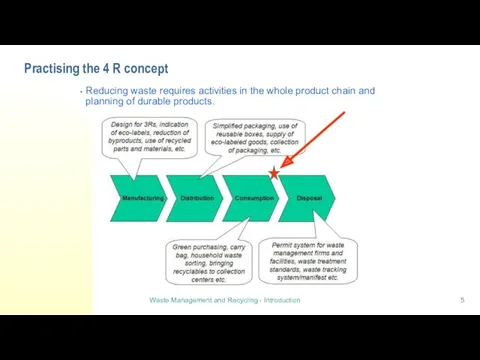
Practising the 4 R concept
Reducing waste requires activities in the whole
Practising the 4 R concept
Reducing waste requires activities in the whole
Lecture 2:
Collection and transport
Lecture 2:
Collection and transport
8.9.2016
Waste management and recycling - Collection and transport
Practises in Household Waste
8.9.2016
Waste management and recycling - Collection and transport
Practises in Household Waste
8.9.2016
Waste management and recycling - Collection and transport
Waste Act
Municipal waste management
8.9.2016
Waste management and recycling - Collection and transport
Waste Act
Municipal waste management
8.9.2016
Waste management and recycling - Collection and transport
Municipal waste management in
8.9.2016
Waste management and recycling - Collection and transport
Municipal waste management in
8.9.2016
Waste management and recycling - Collection and transport
How waste management is
8.9.2016
Waste management and recycling - Collection and transport
How waste management is
8.9.2016
Waste management and recycling - Collection and transport
Waste collection
Requirements for waste
8.9.2016
Waste management and recycling - Collection and transport
Waste collection
Requirements for waste
8.9.2016
Waste management and recycling - Collection and transport
Household waste collection
Private household
Biowaste
8.9.2016
Waste management and recycling - Collection and transport
Household waste collection
Private household
Biowaste
8.9.2016
Waste management and recycling - Collection and transport
Housing company waste
Mixed
8.9.2016
Waste management and recycling - Collection and transport
Housing company waste
Mixed
8.9.2016
Waste management and recycling - Collection and transport
Public waste collection sites
Waste
8.9.2016
Waste management and recycling - Collection and transport
Public waste collection sites
Waste
8.9.2016
Waste management and recycling - Collection and transport
Public waste collection sites
Modern
8.9.2016
Waste management and recycling - Collection and transport
Public waste collection sites
Modern
8.9.2016
Waste management and recycling - Collection and transport
Logistics in waste transport
The
8.9.2016
Waste management and recycling - Collection and transport
Logistics in waste transport
The
8.9.2016
Waste management and recycling - Collection and transport
Waste collection trucks for
8.9.2016
Waste management and recycling - Collection and transport
Waste collection trucks for
8.9.2016
Waste management and recycling - Collection and transport
Logistics and transport routes
8.9.2016
Waste management and recycling - Collection and transport
Logistics and transport routes
8.9.2016
Waste management and recycling - Collection and transport
Cost of waste collection
8.9.2016
Waste management and recycling - Collection and transport
Cost of waste collection
Lecture 3: Waste sorting
Lecture 3: Waste sorting
8.9.2016
Waste management and recycling - Sorting
Waste types
Waste should be sorted for
8.9.2016
Waste management and recycling - Sorting
Waste types
Waste should be sorted for
8.9.2016
Waste management and recycling - Sorting
Waste centre in Lahti
Sorted waste is
8.9.2016
Waste management and recycling - Sorting
Waste centre in Lahti
Sorted waste is
8.9.2016
Waste management and recycling - Sorting
Recyclable materials sorted at source
Waste
8.9.2016
Waste management and recycling - Sorting
Recyclable materials sorted at source
Waste
8.9.2016
Waste management and recycling - Sorting
Biowaste
Biowaste is organic, biologically degradable waste
8.9.2016
Waste management and recycling - Sorting
Biowaste
Biowaste is organic, biologically degradable waste
8.9.2016
Waste management and recycling - Sorting
Waste for energy recovery
In general paper
8.9.2016
Waste management and recycling - Sorting
Waste for energy recovery
In general paper
8.9.2016
Waste management and recycling - Sorting
Waste for landfill
Waste not possible to
8.9.2016
Waste management and recycling - Sorting
Waste for landfill
Waste not possible to
8.9.2016
Waste management and recycling - Sorting
Material recovery facility
MSW is not sorted
8.9.2016
Waste management and recycling - Sorting
Material recovery facility
MSW is not sorted
8.9.2016
Waste management and recycling - Sorting
Material prices in USA 2002
8.9.2016
Waste management and recycling - Sorting
Material prices in USA 2002
8.9.2016
Waste management and recycling - Sorting
MRF facility
Commingled recyclable material is sorted
8.9.2016
Waste management and recycling - Sorting
MRF facility
Commingled recyclable material is sorted

8.9.2016
Waste management and recycling - Sorting
Processing of and recovery from mixed
8.9.2016
Waste management and recycling - Sorting
Processing of and recovery from mixed
8.9.2016
Waste management and recycling - Sorting
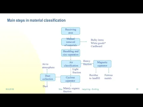
Main steps in material classification
8.9.2016
Waste management and recycling - Sorting
Main steps in material classification
8.9.2016
Waste management and recycling - Sorting
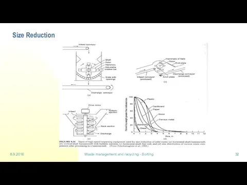
Size Reduction
8.9.2016
Waste management and recycling - Sorting
Size Reduction
8.9.2016
Waste management and recycling - Sorting
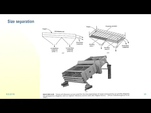
Size separation
8.9.2016
Waste management and recycling - Sorting
Size separation
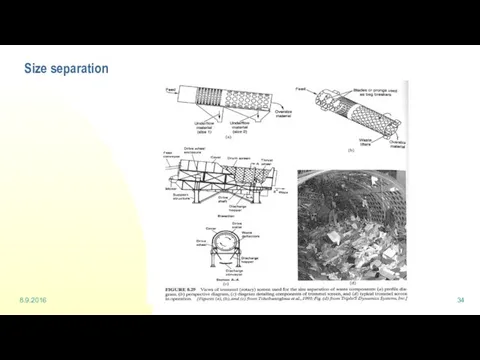
8.9.2016
Waste management and recycling - Sorting
Size separation
8.9.2016
Waste management and recycling - Sorting
Size separation
8.9.2016
Waste management and recycling - Sorting
Magnetic separation
8.9.2016
Waste management and recycling - Sorting
Magnetic separation
8.9.2016
Waste management and recycling - Sorting
Air classifier
8.9.2016
Waste management and recycling - Sorting
Air classifier
8.9.2016
Waste management and recycling - Sorting
Automated sorting system with sensors
8.9.2016
Waste management and recycling - Sorting
Automated sorting system with sensors
Lecture 4: Landfill
Lecture 4: Landfill
22.9.2016
Waste management and recycling - Landfill
Gas collection and utilization system
Gas collection
22.9.2016
Waste management and recycling - Landfill
Gas collection and utilization system
Gas collection
22.9.2016
Waste management and recycling - Landfill
Planning of a landfill
Siting is a
22.9.2016
Waste management and recycling - Landfill
Planning of a landfill
Siting is a
22.9.2016
Waste management and recycling - Landfill
Gas formation in anaerobic processes
Micro-organisms come
22.9.2016
Waste management and recycling - Landfill
Gas formation in anaerobic processes
Micro-organisms come
22.9.2016
Waste management and recycling - Landfill
Gas formation…
Phase IV – methane fermentation
22.9.2016
Waste management and recycling - Landfill
Gas formation…
Phase IV – methane fermentation
22.9.2016
Waste management and recycling - Landfill
Formation of leachate
Amount of leachate varies
22.9.2016
Waste management and recycling - Landfill
Formation of leachate
Amount of leachate varies
22.9.2016
Waste management and recycling - Landfill
Leachate
Quality of leachate depends on
the
22.9.2016
Waste management and recycling - Landfill
Leachate
Quality of leachate depends on
the
22.9.2016
Waste management and recycling - Landfill
Construction of a landfill before filling
22.9.2016
Waste management and recycling - Landfill
Construction of a landfill before filling
22.9.2016
Waste management and recycling - Landfill
Filling
Filling system depends on topography
Waste is
22.9.2016
Waste management and recycling - Landfill
Filling
Filling system depends on topography
Waste is
22.9.2016
Waste management and recycling - Landfill
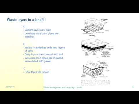
Waste layers in a landfill
a)
Bottom layers
22.9.2016
Waste management and recycling - Landfill
Waste layers in a landfill
a)
Bottom layers
22.9.2016
Waste management and recycling - Landfill
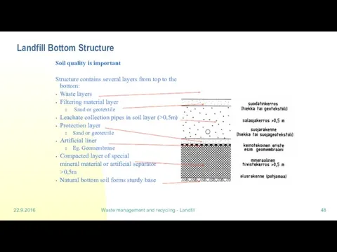
Landfill Bottom Structure
Soil quality is important
22.9.2016
Waste management and recycling - Landfill
Landfill Bottom Structure
Soil quality is important
22.9.2016
Waste management and recycling - Landfill
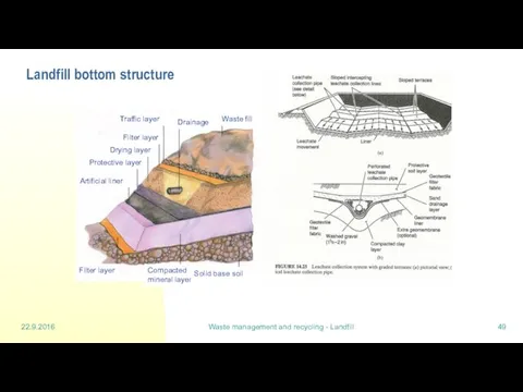
Landfill bottom structure
Waste fill
Drainage
Traffic layer
Filter layer
Drying
22.9.2016
Waste management and recycling - Landfill
Landfill bottom structure
Waste fill
Drainage
Traffic layer
Filter layer
Drying
22.9.2016
Waste management and recycling - Landfill
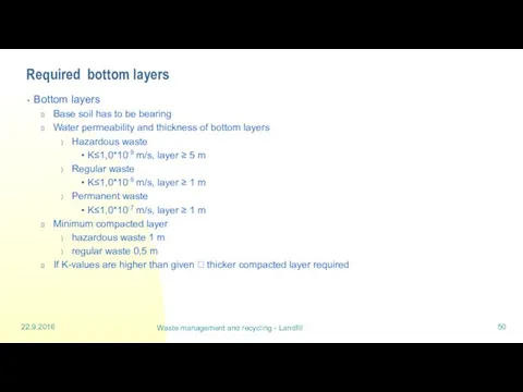
Required bottom layers
Bottom layers
Base soil has
22.9.2016
Waste management and recycling - Landfill
Required bottom layers
Bottom layers
Base soil has
22.9.2016
Waste management and recycling - Landfill
An example of bottom liners and
22.9.2016
Waste management and recycling - Landfill
An example of bottom liners and
Lecture 5:
Composting (part 1)
Lecture 5:
Composting (part 1)
29.9.2016
Waste management and recycling - Composting
Definitions
Composting = aerobic biological decomposition
29.9.2016
Waste management and recycling - Composting
Definitions
Composting = aerobic biological decomposition
29.9.2016
Waste management and recycling - Composting
The four phases of decomposition
29.9.2016
Waste management and recycling - Composting
The four phases of decomposition
29.9.2016
Waste management and recycling - Composting
The five phases of decomposition
29.9.2016
Waste management and recycling - Composting
The five phases of decomposition
29.9.2016
Waste management and recycling - Composting
Factors affecting the decomposition in
29.9.2016
Waste management and recycling - Composting
Factors affecting the decomposition in
29.9.2016
Waste management and recycling - Composting
Factors affecting the decomposition in
29.9.2016
Waste management and recycling - Composting
Factors affecting the decomposition in
29.9.2016
Waste management and recycling - Composting
Factors affecting the decomposition in
29.9.2016
Waste management and recycling - Composting
Factors affecting the decomposition in
29.9.2016
Waste management and recycling - Composting
Factors affecting the decomposition in
29.9.2016
Waste management and recycling - Composting
Factors affecting the decomposition in
29.9.2016
Waste management and recycling - Composting
Materials and elements in composting
Often
29.9.2016
Waste management and recycling - Composting
Materials and elements in composting
Often
29.9.2016
Waste management and recycling - Composting
Factors affecting the decomposition in
29.9.2016
Waste management and recycling - Composting
Factors affecting the decomposition in
29.9.2016
Waste management and recycling - Composting
Factors affecting the decomposition in
29.9.2016
Waste management and recycling - Composting
Factors affecting the decomposition in
29.9.2016
Waste management and recycling - Composting
Properties affecting composting
Taulukko 3.1 Jätteen
29.9.2016
Waste management and recycling - Composting
Properties affecting composting
Taulukko 3.1 Jätteen
Lecture 6: Digestion
Lecture 6: Digestion
6.10.2016
Waste management and recycling - Digestion
Basics of digestion
Treatment for biological waste
6.10.2016
Waste management and recycling - Digestion
Basics of digestion
Treatment for biological waste
6.10.2016
Waste management and recycling - Digestion
Classification of anaerobic processes
Wet process: total
6.10.2016
Waste management and recycling - Digestion
Classification of anaerobic processes
Wet process: total
6.10.2016
Waste management and recycling - Digestion
Digestion process
Biological reactions in the
6.10.2016
Waste management and recycling - Digestion
Digestion process
Biological reactions in the
6.10.2016
Waste management and recycling - Digestion
Digestion process
Methanogenesis: methane - forming bacteria
6.10.2016
Waste management and recycling - Digestion
Digestion process
Methanogenesis: methane - forming bacteria
6.10.2016
Waste management and recycling - Digestion
Substrate dissimilation in anaerobic process
Protein
Carbohydrate
Fat
Long
6.10.2016
Waste management and recycling - Digestion
Substrate dissimilation in anaerobic process
Protein
Carbohydrate
Fat
Long
6.10.2016
Waste management and recycling - Digestion
Gas formation in anaerobic processes
See anaerobic
6.10.2016
Waste management and recycling - Digestion
Gas formation in anaerobic processes
See anaerobic
Lecture 7:
Waste incineration (part 2)
Lecture 7:
Waste incineration (part 2)
13.10.2016
Waste management and recycling - incineration 2
7.10 Thermal treatment methods of
13.10.2016
Waste management and recycling - incineration 2
7.10 Thermal treatment methods of
13.10.2016
Waste management and recycling - incineration 2
7.10.2 Municipal waste incineration plants
13.10.2016
Waste management and recycling - incineration 2
7.10.2 Municipal waste incineration plants
13.10.2016
Waste management and recycling - incineration 2
Grate firing
Grate firing basics
Fuel
13.10.2016
Waste management and recycling - incineration 2
Grate firing
Grate firing basics
Fuel
13.10.2016
Waste management and recycling - incineration 2
Grate firing (cont)
Different air flows
13.10.2016
Waste management and recycling - incineration 2
Grate firing (cont)
Different air flows
13.10.2016
Waste management and recycling - incineration 2
Grate firing (cont)
Grate structure (VonRoll
13.10.2016
Waste management and recycling - incineration 2
Grate firing (cont)
Grate structure (VonRoll
13.10.2016
Waste management and recycling - incineration 2
Grate firing (cont)
The grate removes
13.10.2016
Waste management and recycling - incineration 2
Grate firing (cont)
The grate removes
13.10.2016
Waste management and recycling - incineration 2
Fluidised bed incineration
Fluidised bed
13.10.2016
Waste management and recycling - incineration 2
Fluidised bed incineration
Fluidised bed
13.10.2016
Waste management and recycling - incineration 2
Fluidised bed incineration (cont)
The purpose
13.10.2016
Waste management and recycling - incineration 2
Fluidised bed incineration (cont)
The purpose
13.10.2016
Waste management and recycling - incineration 2
Fluidised bed incineration (cont)
Fluidised
13.10.2016
Waste management and recycling - incineration 2
Fluidised bed incineration (cont)
Fluidised
13.10.2016
Waste management and recycling - incineration 2
The structure of the fluidised
13.10.2016
Waste management and recycling - incineration 2
The structure of the fluidised
13.10.2016
Waste management and recycling - incineration 2
Fluidised bed techniques
Common
The bed
13.10.2016
Waste management and recycling - incineration 2
Fluidised bed techniques
Common
The bed
13.10.2016
Waste management and recycling - incineration 2
Fluidised bed techniques (cont)
Small emissions
13.10.2016
Waste management and recycling - incineration 2
Fluidised bed techniques (cont)
Small emissions
13.10.2016
Waste management and recycling - incineration 2
7.10.3 Pyrolysis and gasification
Optional
13.10.2016
Waste management and recycling - incineration 2
7.10.3 Pyrolysis and gasification
Optional
13.10.2016
Waste management and recycling - incineration 2
Pyrolysis and gasification (cont)
Smouldering
Gas formation
13.10.2016
Waste management and recycling - incineration 2
Pyrolysis and gasification (cont)
Smouldering
Gas formation
13.10.2016
Waste management and recycling - incineration 2
Gasification
Several processes suitable for municipal
13.10.2016
Waste management and recycling - incineration 2
Gasification
Several processes suitable for municipal
13.10.2016
Waste management and recycling - incineration 2
Gasification (cont)
Example of gasification of
13.10.2016
Waste management and recycling - incineration 2
Gasification (cont)
Example of gasification of
13.10.2016
Waste management and recycling - incineration 2
Gasification (cont
Pressurised gasification (BREF, 2003)
13.10.2016
Waste management and recycling - incineration 2
Gasification (cont
Pressurised gasification (BREF, 2003)
13.10.2016
Waste management and recycling - incineration 2
Gasification Figures (cont)
Concurrent gasifier (BREF,
13.10.2016
Waste management and recycling - incineration 2
Gasification Figures (cont)
Concurrent gasifier (BREF,
13.10.2016
Waste management and recycling - incineration 2
Gasification (cont)
Benefits
gasification enables also
13.10.2016
Waste management and recycling - incineration 2
Gasification (cont)
Benefits
gasification enables also
13.10.2016
Waste management and recycling - incineration 2
Gasification (cont)
Negative features
new
13.10.2016
Waste management and recycling - incineration 2
Gasification (cont)
Negative features
new
Lecture 8:
Hazardous waste
Lecture 8:
Hazardous waste
20.10.2016
Waste management and recycling - Hazardous waste
Is the list definite?
If a
20.10.2016
Waste management and recycling - Hazardous waste
Is the list definite?
If a
Types of hazardous waste
Solid wastes
Liquid wastes
Chemicals
Industrial wastes
Well known; in environmental permits
Mainly
Types of hazardous waste
Solid wastes
Liquid wastes
Chemicals
Industrial wastes
Well known; in environmental permits
Mainly
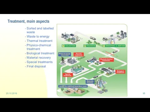
Treatment, main aspects
Sorted and labelled waste
Waste to energy
Thermal treatment
Physico-chemical treatment
Biological
Treatment, main aspects
Sorted and labelled waste
Waste to energy
Thermal treatment
Physico-chemical treatment
Biological
1 High temperature incineration
Process units at Ekokem
The core unit is a
1 High temperature incineration
Process units at Ekokem
The core unit is a
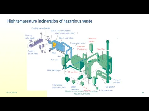
High temperature incineration of hazardous waste
20.10.2016
Waste management and recycling - Hazardous
High temperature incineration of hazardous waste
20.10.2016
Waste management and recycling - Hazardous
4 Physico- chemical processes
Inorganic wastes, such as acids, bases and heavy
4 Physico- chemical processes
Inorganic wastes, such as acids, bases and heavy
Physico-chemical processes
20.10.2016
Waste management and recycling - Hazardous waste
Non-soluble
heavy metal salts
Physico-chemical processes
20.10.2016
Waste management and recycling - Hazardous waste
Non-soluble
heavy metal salts
Lecture 9:
Life cycle assessment
Lecture 9:
Life cycle assessment
Waste management and recycling - LCA
10 Life Cycle Assessment = LCA
Various
Waste management and recycling - LCA
10 Life Cycle Assessment = LCA
Various
Waste management and recycling - LCA
Life Cycle Assessment = LCA
Main idea
Waste management and recycling - LCA
Life Cycle Assessment = LCA
Main idea
Waste management and recycling - LCA
LCA, what is it for?
Companies
Cleaner processes
Waste management and recycling - LCA
LCA, what is it for?
Companies
Cleaner processes
Waste management and recycling - LCA
Unit process
A unit process can be
Waste management and recycling - LCA
Unit process
A unit process can be
Waste management and recycling - LCA
A system is made up of
Waste management and recycling - LCA
A system is made up of
Waste management and recycling - LCA
Different emissions cause different things in
Waste management and recycling - LCA
Different emissions cause different things in
Waste management and recycling - LCA
Impact assessment methods - Midpoint
Methods are
Waste management and recycling - LCA
Impact assessment methods - Midpoint
Methods are
Waste management and recycling - LCA
Impact assessment methods - Midpoint cont.
Midpoint-oriented
Waste management and recycling - LCA
Impact assessment methods - Midpoint cont.
Midpoint-oriented
 Гигиеническая характеристика основных методов очистки сточных вод
 Отчет о проведении краевой экологической акции Зеленая волна
 Охрана природы
 How to save the Earth
 Вторая жизнь ненужных вещей
 Инженерная защита окружающей среды
 Мониторинг окружающей среды
 Высокотоксичные соединения в атмосфере
 Мікологія та альгологія. Тема 4. Група відділів псевдогрибів
 Урок Без потерь. Фудшеринг и культура рационального потребления
 City Life and Country Life
 Раздельный сбор мусора
 Современное состояние и рациональное использование почвенных ресурсов Белоруссии (лекция 3)
 Загрязнение Мирового океана
 Влияние электричества и электростанций на окружающую среду
 Valsts, civilā un vides aizsardzība. Katastrofas, to iedalījums un veidi. Terorisms, cīņa ar terorismu
 Экологические проблемы
 02.2022 Биология 11 класс
 ҚР зкологиялық дағдарыс және экологиялық апатты аймақтары
 Қоршаған ортаның биологиялық ластануы және оның адам денсаулығына әсері
 Загрязнение Мирового океана
 Лишайники, как индикатор загрязнения городской среды
 Зеленая планета
 Правовые основы природопользования. Лекция 13
 Альтернативное зелёное топливо
 Екологічні проблеми та їх розв’язування
 Ластану және қалдықтарды кәдеге жарату. Қолданыстан шыққан материалдарды қайта өңдеу мүмкіндіктері
 Экологические основы безопасности жизнедеятельности человека в среде обитания. 10 класс