- Engine

Содержание
- 2. Very clean engine In compliance with following homologations: 97/68 CE Stage 2 and EPA Tier 2
- 3. Engine : Gas Emission
- 4. Engine : Performance Curves
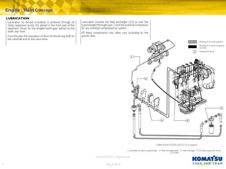
- 5. Engine : Main Concept
- 6. Engine : Main Concept
- 7. Longitudinal section of injection pump 1. Membrane - 2. Adjusting hub nut - 3. Feeler -
- 8. Engine : Fuel Injection Pump Operation
- 9. L.D.A. Mode of operation The LDA device adjusts the fuel throughput independent of the air pressure
- 10. Design of the controller with feed-dependent adjustment of the start of delivery 1. Control spring -
- 11. The KKSB device allows to set the required cold start injection advance. Engine : Fuel Injection
- 12. Engine : Fuel Injection Timing Inspection and adjustment
- 13. Engine : Turbocharger
- 14. Engine : Repair Kit Bearing (-0,25 mm) Bearing (-0,50 mm) Bearing (-0,25 mm) Bearing (-0,50 mm)
- 15. Engine : Workshop Data
- 16. Engine : Workshop Data
- 17. Exhaust manifold Turbo compressor: - first step: 4-3-1-2 - second step: 1-4-2-3 Oil pan: - first
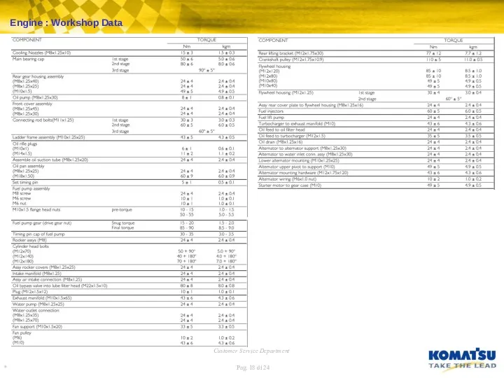
- 18. Engine : Workshop Data
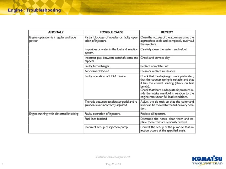
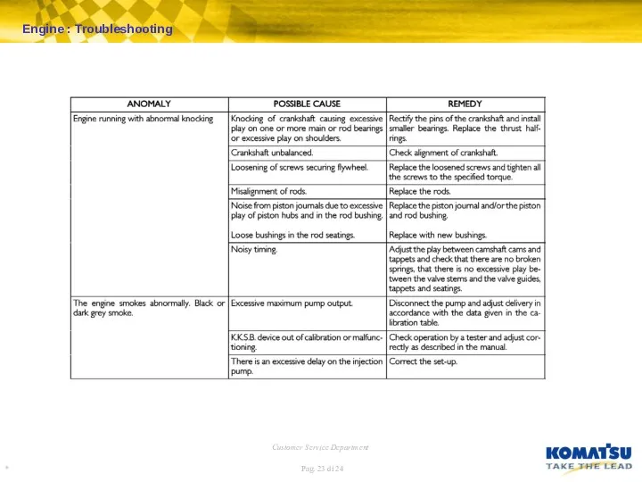
- 19. Engine : Troubleshooting
- 20. Engine : Troubleshooting
- 21. Engine : Troubleshooting
- 22. Engine : Troubleshooting
- 23. Engine : Troubleshooting
- 25. Скачать презентацию
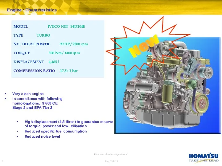
Very clean engine
In compliance with following homologations: 97/68 CE Stage 2
Very clean engine
In compliance with following homologations: 97/68 CE Stage 2
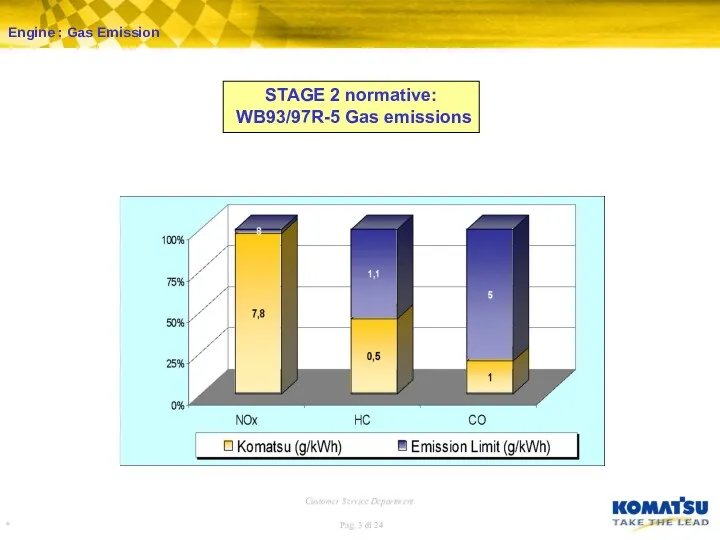
Engine : Gas Emission
Engine : Gas Emission
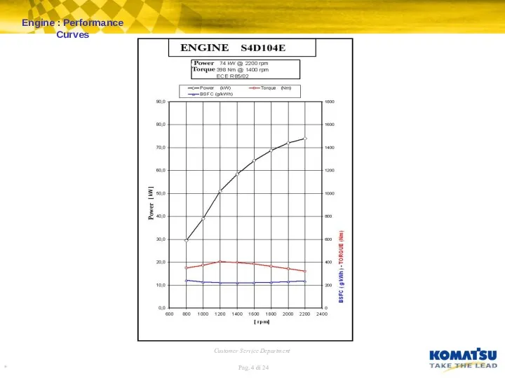
Engine : Performance Curves
Engine : Performance Curves
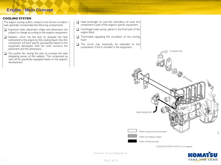
Engine : Main Concept
Engine : Main Concept
Engine : Main Concept
Engine : Main Concept
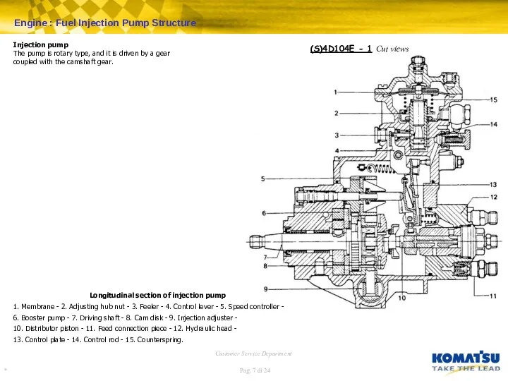
Longitudinal section of injection pump
1. Membrane - 2. Adjusting hub nut
Longitudinal section of injection pump
1. Membrane - 2. Adjusting hub nut
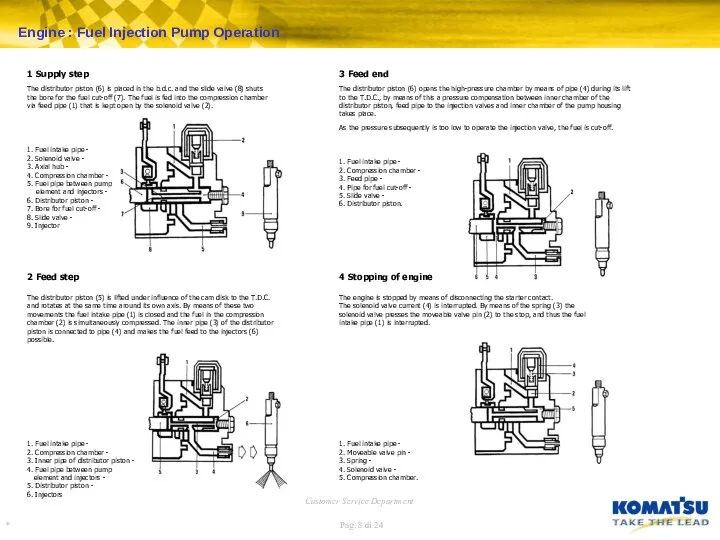
Engine : Fuel Injection Pump Operation
Engine : Fuel Injection Pump Operation
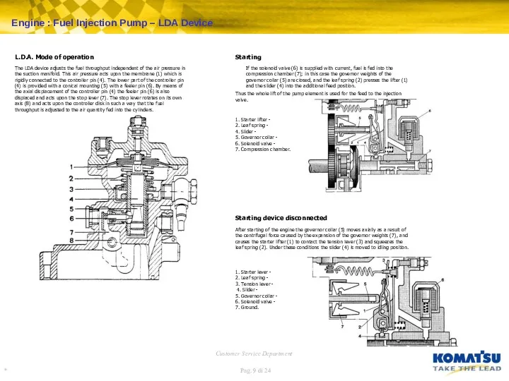
L.D.A. Mode of operation
The LDA device adjusts the fuel throughput independent
L.D.A. Mode of operation
The LDA device adjusts the fuel throughput independent
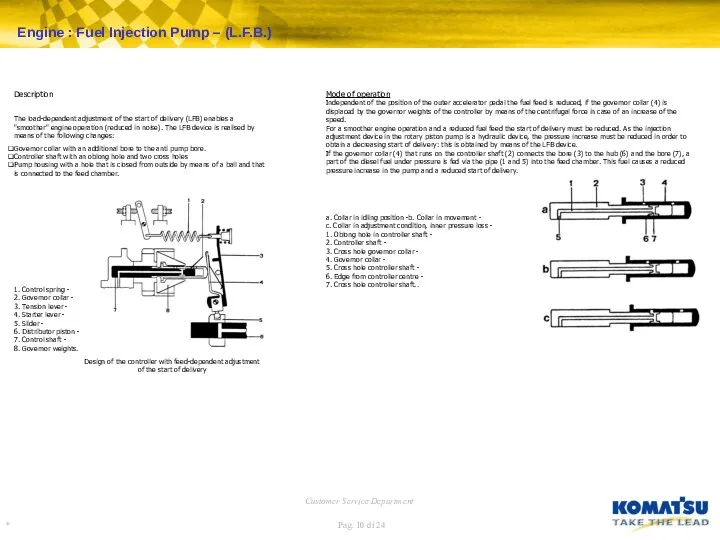
Design of the controller with feed-dependent adjustment
of the start of
Design of the controller with feed-dependent adjustment of the start of
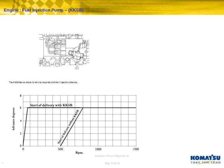
The KKSB device allows to set the required cold start injection
The KKSB device allows to set the required cold start injection
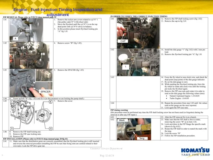
Engine : Fuel Injection Timing Inspection and adjustment
Engine : Fuel Injection Timing Inspection and adjustment
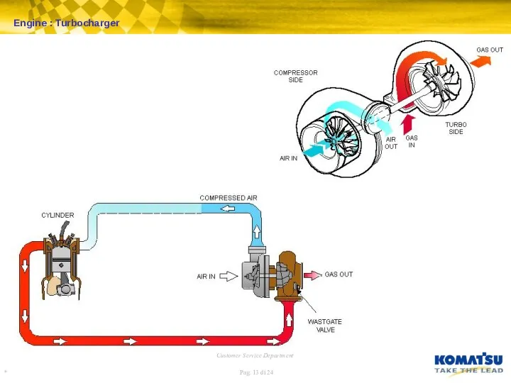
Engine : Turbocharger
Engine : Turbocharger
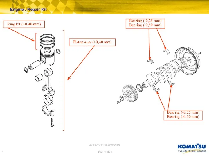
Engine : Repair Kit
Bearing (-0,25 mm)
Bearing (-0,50 mm)
Bearing (-0,25 mm)
Bearing (-0,50
Engine : Repair Kit
Bearing (-0,25 mm)
Bearing (-0,50 mm)
Bearing (-0,25 mm)
Bearing (-0,50
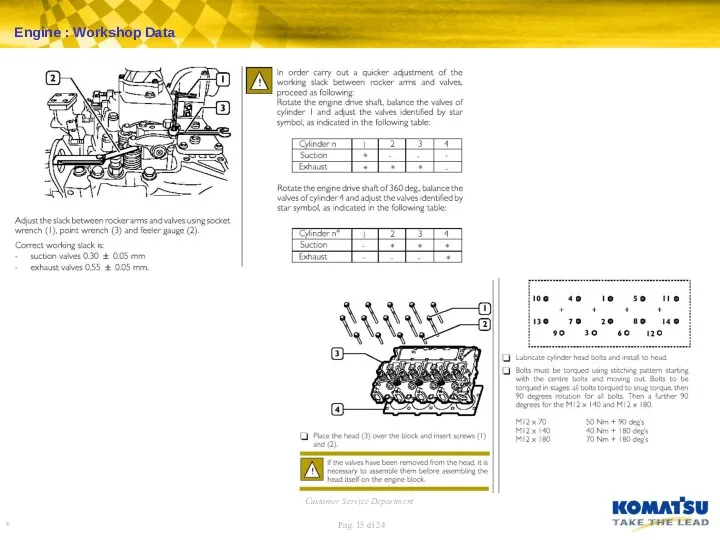
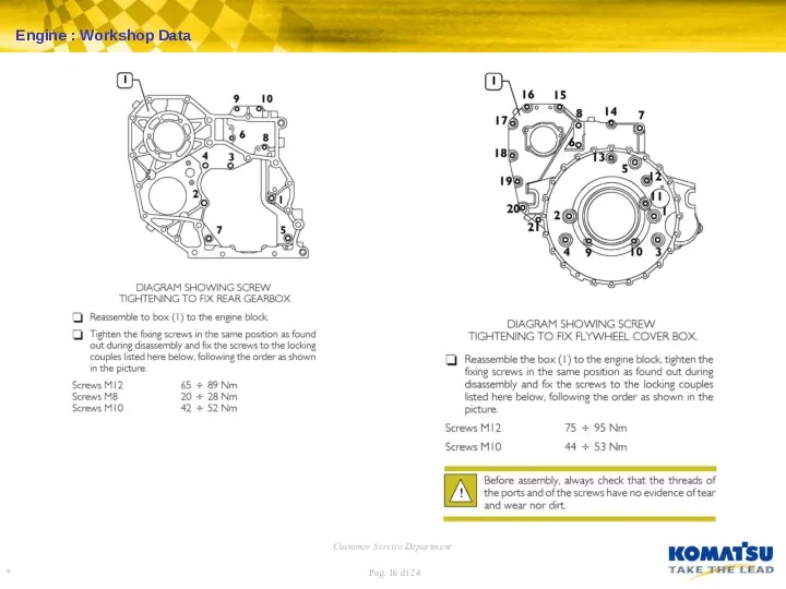
Engine : Workshop Data
Engine : Workshop Data
Engine : Workshop Data
Engine : Workshop Data
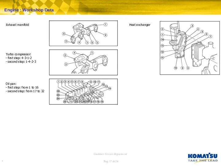
Exhaust manifold
Turbo compressor:
- first step: 4-3-1-2
- second step: 1-4-2-3
Oil pan:
- first
Exhaust manifold
Turbo compressor:
- first step: 4-3-1-2
- second step: 1-4-2-3
Oil pan: - first
Engine : Workshop Data
Engine : Workshop Data
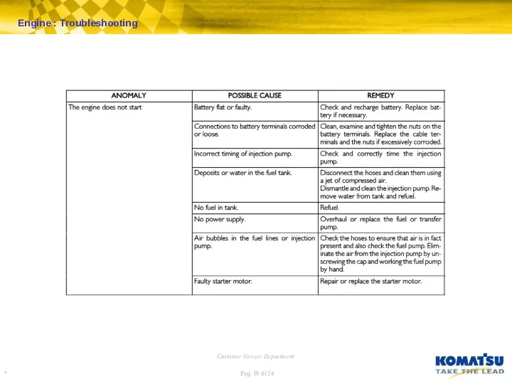
Engine : Troubleshooting
Engine : Troubleshooting
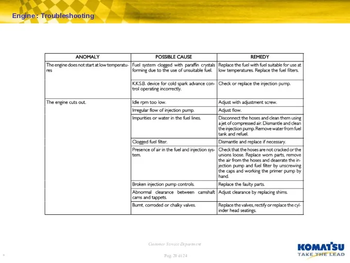
Engine : Troubleshooting
Engine : Troubleshooting
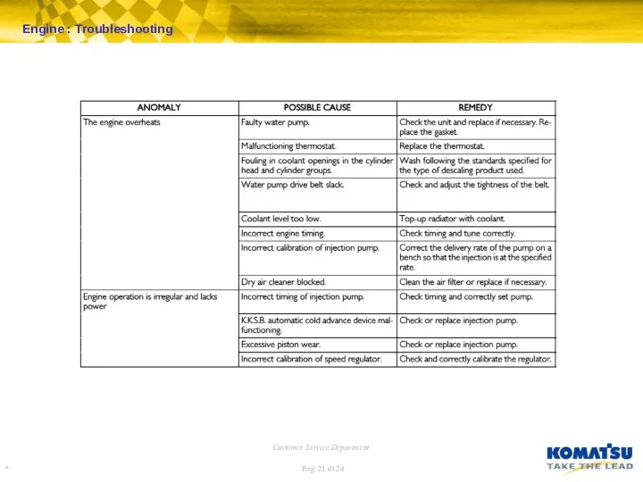
Engine : Troubleshooting
Engine : Troubleshooting
Engine : Troubleshooting
Engine : Troubleshooting
Engine : Troubleshooting
Engine : Troubleshooting
 Постоянный электрический ток
 Отчет по учебной практике. Радарный уровнемер Saab TankRadar RTG 3920
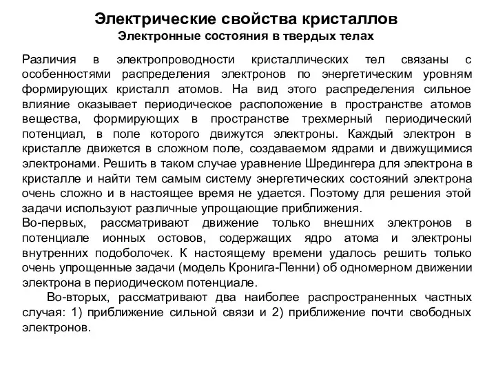 Электрические свойства кристаллов
 Электризация тел при соприкосновении. Взаимодействие заряженных тел. Два рода электрических зарядов
 Мастер-класс : Формирование познавательных УУД на уроках физики и внеурочной деятельности Буданова Ольга Евгеньевна, учитель физики МБОУ СОШ №128.
 Құрылыс материалдарының физикалық қасиеттері
 Давление. Физика, 7 класс
 Виды спектров. Спектральный анализ
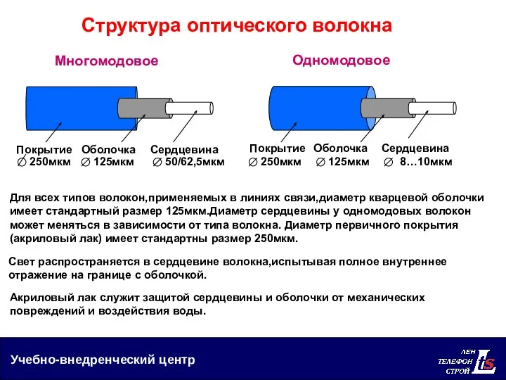 Структура оптического волокна
 Лопушнян Г.А.Теория света.
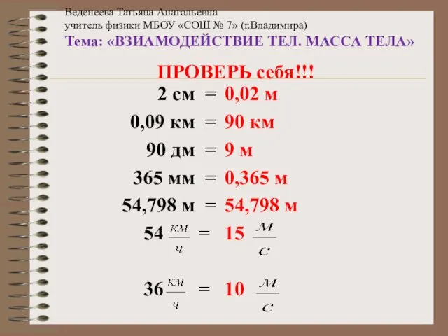 ВЗИАМОДЕЙСТВИЕ ТЕЛ. МАССА ТЕЛА
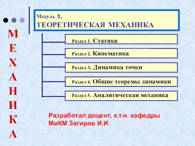 ЛЕКЦИИ термех. модуль 1
 Закон отражения света
 Тепловое излучение. Фотон. Внешний фотоэффект. Лекция № 5
 Ядерный реактор. Получение радиоактивных изотопов и их применение
 Презентация к уроку в 9 классе на тему: Реактивное движение
 двигатель внутреннего сгорания
 Задачи на встречное движение
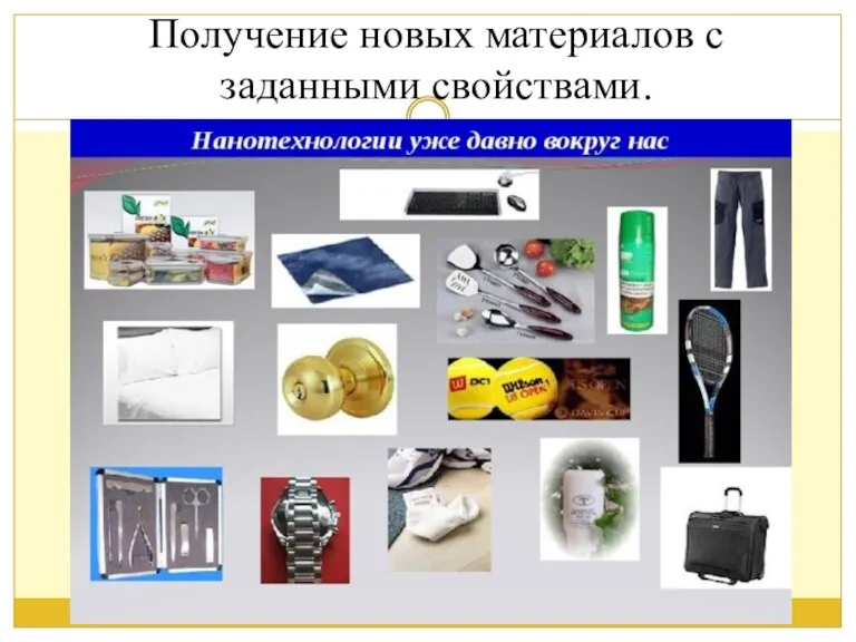 Получение материалов с заданными свойствами
 Электроемкость. Конденсаторы
 Колебательный контур. Электромагнитные колебания
 Итоговая работа. Методология научного исследования. Исследование распространения звуковых волн в новых материалах
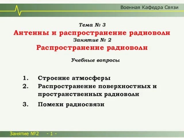 Антенны и распространение радиоволн
 Тепловые двигатели
 Электрический ток. Источники электрического тока
 Электрический ток в различных средах
 Diesel and petrol power
 Фізичні й хімічні явища у природі