- Engine overall. Model outline for technician

Содержание
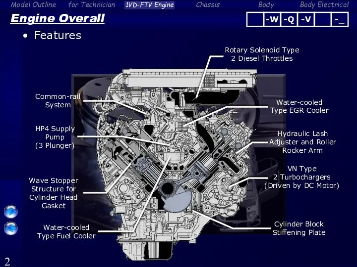
- 2. Engine Overall Features Cylinder Block Stiffening Plate Hydraulic Lash Adjuster and Roller Rocker Arm VN Type
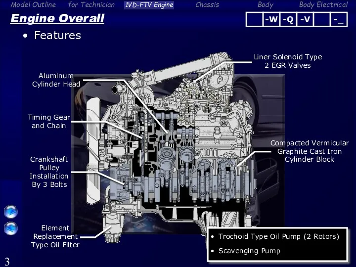
- 3. Engine Overall Features Crankshaft Pulley Installation By 3 Bolts Timing Gear and Chain Liner Solenoid Type
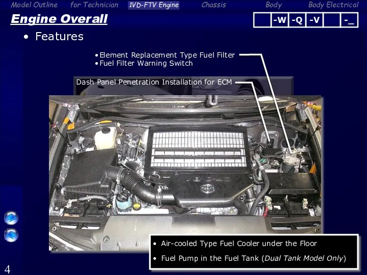
- 4. Engine Overall Features Element Replacement Type Fuel Filter Fuel Filter Warning Switch Dash Panel Penetration Installation
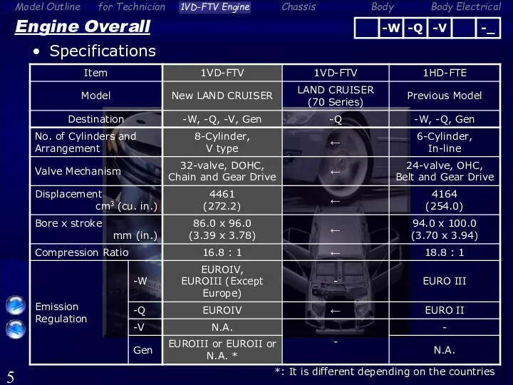
- 5. Engine Overall Specifications *: It is different depending on the countries
- 6. Engine Overall Specifications *: Only for -W models equipped with a pre-cleaner
- 7. Reference (Engine Overall) Major Difference From LAND CRUISER (VDJ70)
- 8. Engine Proper Cylinder Block High strength compacted vermicular graphite cast iron is used for weight reduction
- 9. Engine Proper Cylinder Head Gasket Wave stopper structure is used around the cylinder bore to improve
- 10. Engine Proper Crankshaft and Flywheel Balance weight is appropriately provided to reduce vibration Oil Pump Drive
- 11. Engine Proper Cylinder Block Stiffening Plate This plate connects the bearing cap and cylinder block skirt
- 12. Engine Proper Crankshaft Pulley Installed by 3 bolts to reduce tightening torque Installation with 3 bolts
- 13. Valve Mechanism Timing Gear and Chain Timing gear and chain is used to realize maintenance-free Crankshaft
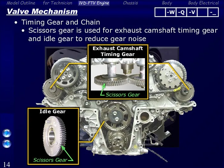
- 14. Valve Mechanism Timing Gear and Chain Scissors gear is used for exhaust camshaft timing gear and
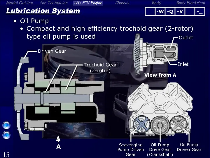
- 15. Lubrication System Oil Pump Compact and high efficiency trochoid gear (2-rotor) type oil pump is used
- 16. Lubrication System Oil Filter Element replacement type oil filter is used Oil Filter Cap (Resin) Oil
- 17. Lubrication System Scavenging Pump This system is used to prevents oil from retaining in the turbocharger
- 18. Lubrication System Scavenging Pump Scavenging pump sucks the engine oil in the catch tank and discharge
- 19. Lubrication System Scavenging Pump Parts Location Turbocharger (LH (Bank2)) Scavenging Pump Oil Catch Tank Ventilation Tube
- 20. Lubrication System Scavenging Pump Scavenging pump is driven by crankshaft Driven Gear A View from A
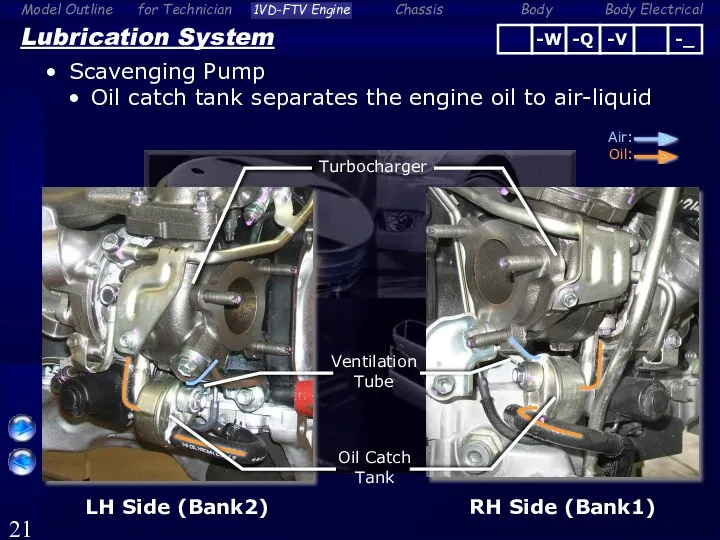
- 21. Lubrication System Scavenging Pump Oil catch tank separates the engine oil to air-liquid Oil Catch Tank
- 22. Reference (Lubrication System) Scavenging Pump Oil flow from oil catch tank to scavenging pump To Scavenging
- 23. Intake and Exhaust System Variable Nozzle Vane Type Turbocharger VN (Variable Nozzle-vane) type 2 turbochargers VN
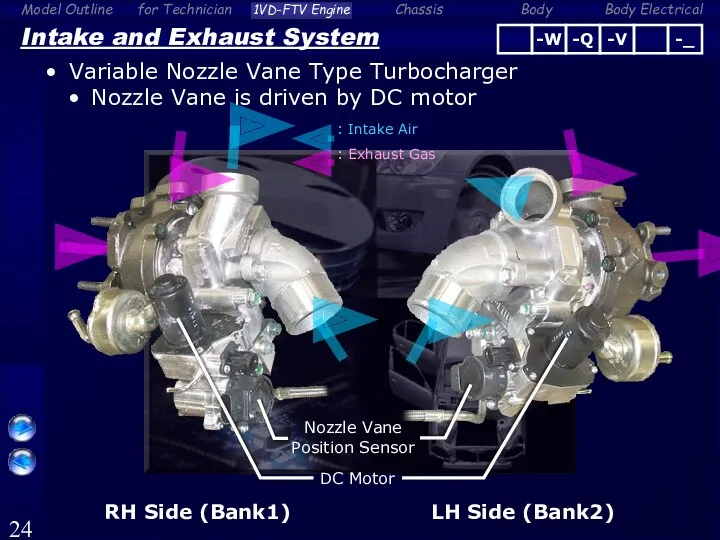
- 24. Intake and Exhaust System Variable Nozzle Vane Type Turbocharger Nozzle Vane is driven by DC motor
- 25. Intake and Exhaust System Variable Nozzle Vane Type Turbocharger Construction (RH Side (Bank1)) DC Motor Linkage
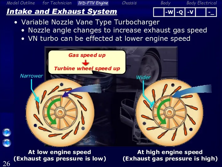
- 26. Intake and Exhaust System Variable Nozzle Vane Type Turbocharger Nozzle angle changes to increase exhaust gas
- 27. ECM Intake and Exhaust System Variable Nozzle Vane Type Turbocharger Control Nozzle Vane Position Turbo Motor
- 28. ECM Turbo Motor Driver [for Bank1 (RH)] EFI Relay +B GND M+ M- VNTI VNTO VN
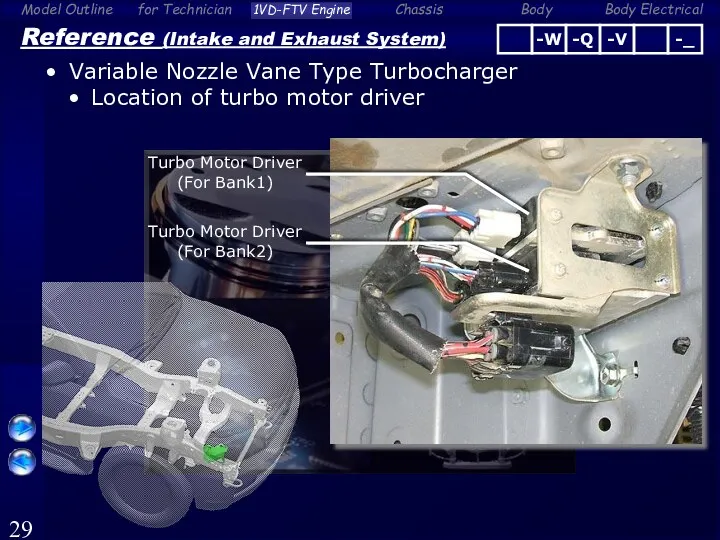
- 29. Reference (Intake and Exhaust System) Variable Nozzle Vane Type Turbocharger Location of turbo motor driver Turbo
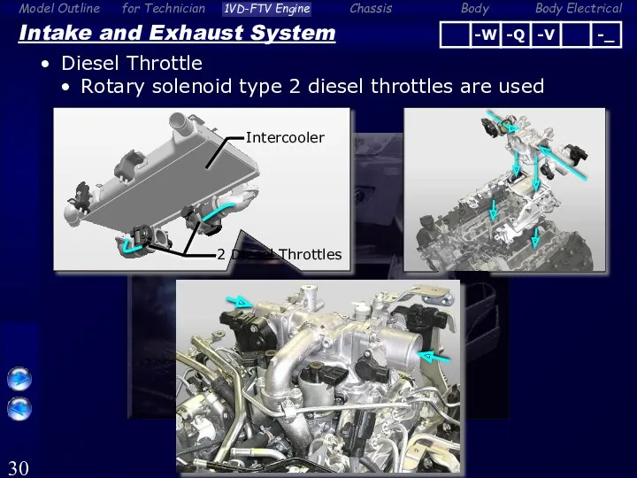
- 30. Intake and Exhaust System Diesel Throttle Rotary solenoid type 2 diesel throttles are used 2 Diesel
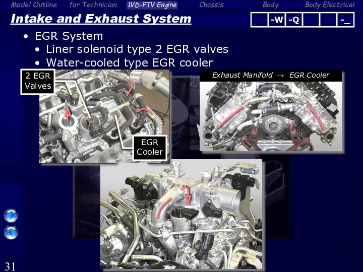
- 31. Intake and Exhaust System EGR System Liner solenoid type 2 EGR valves Water-cooled type EGR cooler
- 32. Fuel System Components and Features 3 Plunger Type HP4 Supply Pump Element Replacement Type Fuel Filter
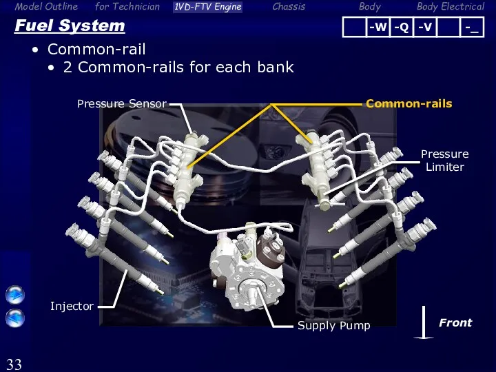
- 33. Fuel System Common-rail 2 Common-rails for each bank Common-rails Pressure Sensor Pressure Limiter Supply Pump Front
- 34. Fuel System Supply Pump (HP4) 3 plunger type supply pump is used to correspond to the
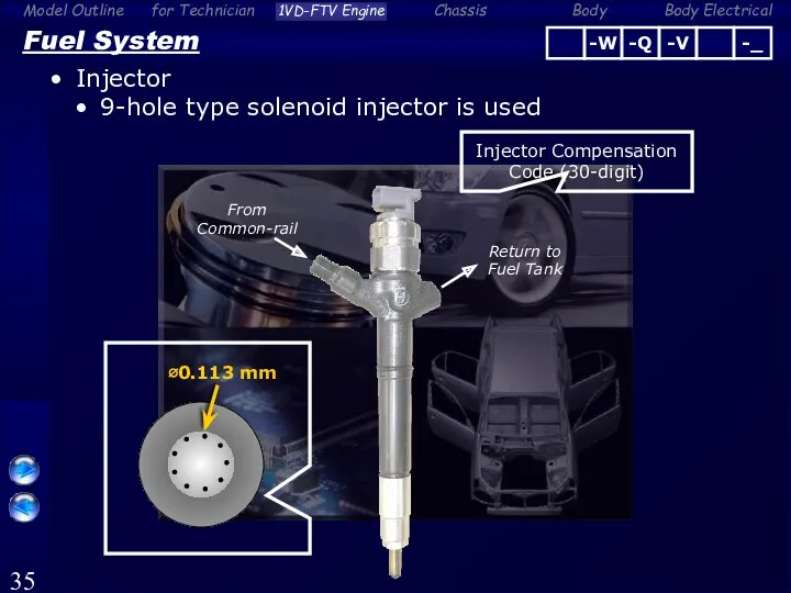
- 35. Fuel System Injector 9-hole type solenoid injector is used From Common-rail Return to Fuel Tank ∅0.113
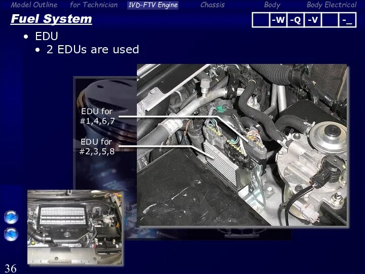
- 36. Fuel System EDU 2 EDUs are used EDU for #1,4,6,7 EDU for #2,3,5,8
- 37. Fuel System Fuel Filter Element replacement type fuel filter is used Fuel Filter From Fuel Tank
- 38. Fuel System Fuel Filter Main Components Filter Element Fuel Sedimenter Level Warning Switch Bolt x3 Fuel
- 39. Fuel System Fuel Filter When the fuel filter clogging is detected by fuel filter warning switch,
- 40. Fuel System Fuel Filter Fuel filter warning switch is turned OFF when the filter outlet pressure
- 41. Analog Type Combination Meter Fuel System Fuel Filter (Analog Type Combination Meter Only) Warning light condition
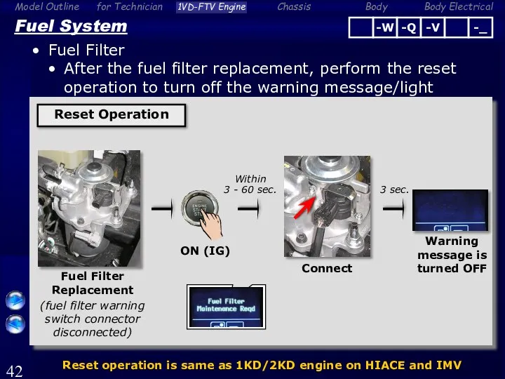
- 42. Fuel System Fuel Filter After the fuel filter replacement, perform the reset operation to turn off
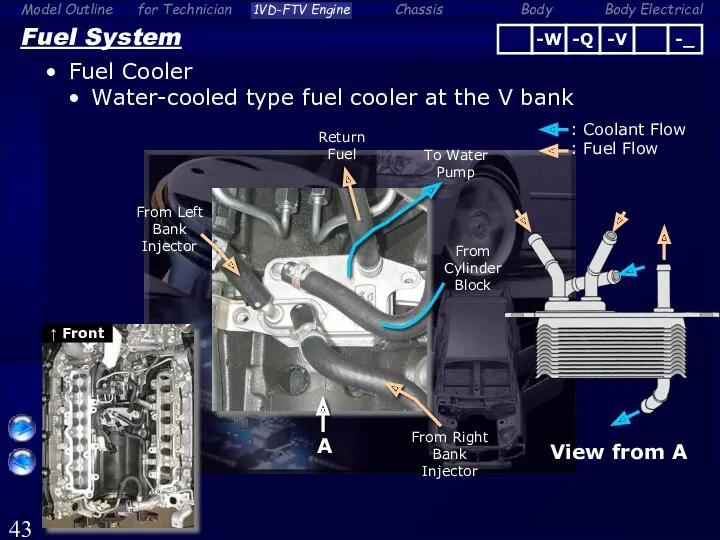
- 43. Fuel System Fuel Cooler Water-cooled type fuel cooler at the V bank From Cylinder Block From
- 44. Fuel System Fuel Cooler Air-cooled type fuel cooler under the floor To Fuel Tank From Engine
- 45. Fuel Tank (Main) [93-liter] Fuel Tank (Sub) [45-liter] Fuel System Fuel Pump (Dual Fuel Tank Model
- 46. Fuel System Fuel Pump (Dual Fuel Tank Model Only) Location Fuel Tank (Main) [93-liter] Fuel Tank
- 47. Fuel System Fuel Pump (Dual Fuel Tank Model Only) ECM controls a fuel pump in accordance
- 48. Fuel System Fuel Pump (Dual Fuel Tank Model Only) When the malfunction is detected in the
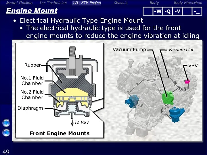
- 49. Engine Mount Electrical Hydraulic Type Engine Mount The electrical hydraulic type is used for the front
- 50. Engine Mount Electrical Hydraulic Type Engine Mount System Diagram Electrical Hydraulic type Engine Mounts Vehicle Speed
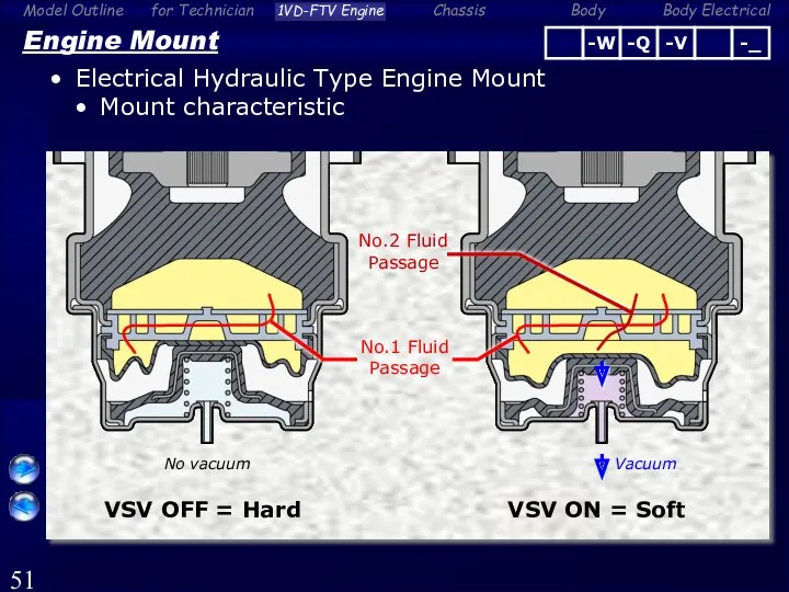
- 51. Engine Mount Electrical Hydraulic Type Engine Mount Mount characteristic VSV ON = Soft VSV OFF =
- 52. VSV OFF (Hard) Engine Mount Electrical Hydraulic Type Engine Mount When the engine is idling and
- 54. Скачать презентацию
Engine Overall
Features
Cylinder Block Stiffening Plate
Hydraulic Lash Adjuster and Roller Rocker Arm
VN
Engine Overall
Features
Cylinder Block Stiffening Plate
Hydraulic Lash Adjuster and Roller Rocker Arm
VN
Engine Overall
Features
Crankshaft Pulley Installation By 3 Bolts
Timing Gear and Chain
Liner Solenoid
Engine Overall
Features
Crankshaft Pulley Installation By 3 Bolts
Timing Gear and Chain
Liner Solenoid
Engine Overall
Features
Element Replacement Type Fuel Filter
Fuel Filter Warning Switch
Dash Panel Penetration
Engine Overall
Features
Element Replacement Type Fuel Filter
Fuel Filter Warning Switch
Dash Panel Penetration
Engine Overall
Specifications
*: It is different depending on the countries
Engine Overall
Specifications
*: It is different depending on the countries
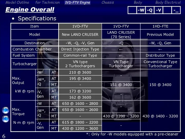
Engine Overall
Specifications
*: Only for -W models equipped with a pre-cleaner
Engine Overall
Specifications
*: Only for -W models equipped with a pre-cleaner

Reference (Engine Overall)
Major Difference From LAND CRUISER (VDJ70)
Reference (Engine Overall)
Major Difference From LAND CRUISER (VDJ70)

Engine Proper
Cylinder Block
High strength compacted vermicular graphite cast iron is used
Engine Proper
Cylinder Block
High strength compacted vermicular graphite cast iron is used

Engine Proper
Cylinder Head Gasket
Wave stopper structure is used around the cylinder
Engine Proper
Cylinder Head Gasket
Wave stopper structure is used around the cylinder

Engine Proper
Crankshaft and Flywheel
Balance weight is appropriately provided to reduce vibration
Oil
Engine Proper
Crankshaft and Flywheel
Balance weight is appropriately provided to reduce vibration
Oil
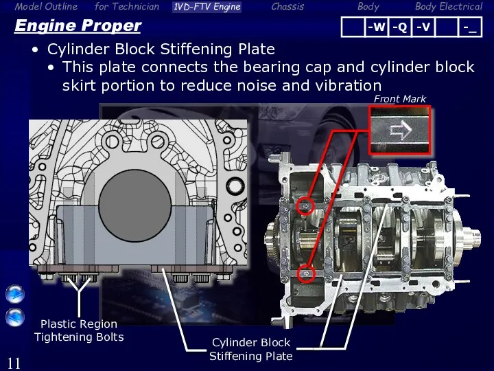
Engine Proper
Cylinder Block Stiffening Plate
This plate connects the bearing cap and
Engine Proper
Cylinder Block Stiffening Plate
This plate connects the bearing cap and
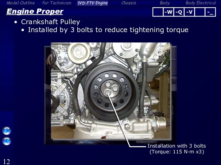
Engine Proper
Crankshaft Pulley
Installed by 3 bolts to reduce tightening torque
Installation with
Engine Proper
Crankshaft Pulley
Installed by 3 bolts to reduce tightening torque
Installation with
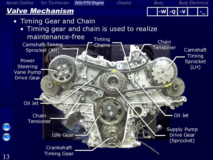
Valve Mechanism
Timing Gear and Chain
Timing gear and chain is used to
Valve Mechanism
Timing Gear and Chain
Timing gear and chain is used to
Valve Mechanism
Timing Gear and Chain
Scissors gear is used for exhaust camshaft
Valve Mechanism
Timing Gear and Chain
Scissors gear is used for exhaust camshaft
Lubrication System
Oil Pump
Compact and high efficiency trochoid gear (2-rotor) type oil
Lubrication System
Oil Pump
Compact and high efficiency trochoid gear (2-rotor) type oil

Lubrication System
Oil Filter
Element replacement type oil filter is used
Oil Filter Cap
(Resin)
Oil
Lubrication System
Oil Filter
Element replacement type oil filter is used
Oil Filter Cap
(Resin)
Oil

Lubrication System
Scavenging Pump
This system is used to prevents oil from retaining
Lubrication System
Scavenging Pump
This system is used to prevents oil from retaining

Lubrication System
Scavenging Pump
Scavenging pump sucks the engine oil in the catch
Lubrication System
Scavenging Pump
Scavenging pump sucks the engine oil in the catch

Lubrication System
Scavenging Pump
Parts Location
Turbocharger
(LH (Bank2))
Scavenging Pump
Oil Catch Tank
Ventilation Tube
Front
Turbocharger
(RH (Bank1))
Oil
Lubrication System
Scavenging Pump
Parts Location
Turbocharger
(LH (Bank2))
Scavenging Pump
Oil Catch Tank
Ventilation Tube
Front
Turbocharger
(RH (Bank1))
Oil

Lubrication System
Scavenging Pump
Scavenging pump is driven by crankshaft
Driven Gear
A
View from A
Outlet
Oil
Lubrication System
Scavenging Pump
Scavenging pump is driven by crankshaft
Driven Gear
A
View from A
Outlet
Oil
Lubrication System
Scavenging Pump
Oil catch tank separates the engine oil to air-liquid
Oil
Lubrication System
Scavenging Pump
Oil catch tank separates the engine oil to air-liquid
Oil

Reference (Lubrication System)
Scavenging Pump
Oil flow from oil catch tank to scavenging
Reference (Lubrication System)
Scavenging Pump
Oil flow from oil catch tank to scavenging

Intake and Exhaust System
Variable Nozzle Vane Type Turbocharger
VN (Variable Nozzle-vane) type
Intake and Exhaust System
Variable Nozzle Vane Type Turbocharger
VN (Variable Nozzle-vane) type
Intake and Exhaust System
Variable Nozzle Vane Type Turbocharger
Nozzle Vane is driven
Intake and Exhaust System
Variable Nozzle Vane Type Turbocharger
Nozzle Vane is driven

Intake and Exhaust System
Variable Nozzle Vane Type Turbocharger
Construction (RH Side (Bank1))
DC
Intake and Exhaust System
Variable Nozzle Vane Type Turbocharger
Construction (RH Side (Bank1))
DC
Intake and Exhaust System
Variable Nozzle Vane Type Turbocharger
Nozzle angle changes to
Intake and Exhaust System
Variable Nozzle Vane Type Turbocharger
Nozzle angle changes to

ECM
Intake and Exhaust System
Variable Nozzle Vane Type Turbocharger
Control
Nozzle Vane Position
Turbo Motor
ECM
Intake and Exhaust System
Variable Nozzle Vane Type Turbocharger
Control
Nozzle Vane Position
Turbo Motor
![ECM Turbo Motor Driver [for Bank1 (RH)] EFI Relay +B](/_ipx/f_webp&q_80&fit_contain&s_1440x1080/imagesDir/jpg/353980/slide-27.jpg)
ECM
Turbo Motor Driver
[for Bank1 (RH)]
EFI Relay
+B
GND
M+
M-
VNTI
VNTO
VN Close
VN Open
Reference (Intake and
ECM
Turbo Motor Driver
[for Bank1 (RH)]
EFI Relay
+B
GND
M+
M-
VNTI
VNTO
VN Close
VN Open
Reference (Intake and
Reference (Intake and Exhaust System)
Variable Nozzle Vane Type Turbocharger
Location of turbo
Reference (Intake and Exhaust System)
Variable Nozzle Vane Type Turbocharger
Location of turbo
Intake and Exhaust System
Diesel Throttle
Rotary solenoid type 2 diesel throttles are
Intake and Exhaust System
Diesel Throttle
Rotary solenoid type 2 diesel throttles are
Intake and Exhaust System
EGR System
Liner solenoid type 2 EGR valves
Water-cooled
Intake and Exhaust System
EGR System
Liner solenoid type 2 EGR valves
Water-cooled

Fuel System
Components and Features
3 Plunger Type HP4 Supply Pump
Element Replacement Type
Fuel System
Components and Features
3 Plunger Type HP4 Supply Pump
Element Replacement Type
Fuel System
Common-rail
2 Common-rails for each bank
Common-rails
Pressure Sensor
Pressure Limiter
Supply Pump
Front
Injector
Fuel System
Common-rail
2 Common-rails for each bank
Common-rails
Pressure Sensor
Pressure Limiter
Supply Pump
Front
Injector

Fuel System
Supply Pump (HP4)
3 plunger type supply pump is used to
Fuel System
Supply Pump (HP4)
3 plunger type supply pump is used to
Fuel System
Injector
9-hole type solenoid injector is used
From
Common-rail
Return to
Fuel Tank
∅0.113 mm
Injector Compensation
Fuel System
Injector
9-hole type solenoid injector is used
From
Common-rail
Return to
Fuel Tank
∅0.113 mm
Injector Compensation
Fuel System
EDU
2 EDUs are used
EDU for #1,4,6,7
EDU for #2,3,5,8
Fuel System
EDU
2 EDUs are used
EDU for #1,4,6,7
EDU for #2,3,5,8

Fuel System
Fuel Filter
Element replacement type fuel filter is used
Fuel Filter
From Fuel
Fuel System
Fuel Filter
Element replacement type fuel filter is used
Fuel Filter
From Fuel

Fuel System
Fuel Filter
Main Components
Filter Element
Fuel Sedimenter Level Warning Switch
Bolt x3
Fuel Filter
Fuel System
Fuel Filter
Main Components
Filter Element
Fuel Sedimenter Level Warning Switch
Bolt x3
Fuel Filter

Fuel System
Fuel Filter
When the fuel filter clogging is detected by fuel
Fuel System
Fuel Filter
When the fuel filter clogging is detected by fuel

Fuel System
Fuel Filter
Fuel filter warning switch is turned OFF when the
Fuel System
Fuel Filter
Fuel filter warning switch is turned OFF when the

Analog Type Combination Meter
Fuel System
Fuel Filter (Analog Type Combination Meter Only)
Warning
Analog Type Combination Meter
Fuel System
Fuel Filter (Analog Type Combination Meter Only)
Warning
Fuel System
Fuel Filter
After the fuel filter replacement, perform the reset operation
Fuel System
Fuel Filter
After the fuel filter replacement, perform the reset operation
Fuel System
Fuel Cooler
Water-cooled type fuel cooler at the V bank
From Cylinder
Fuel System
Fuel Cooler
Water-cooled type fuel cooler at the V bank
From Cylinder

Fuel System
Fuel Cooler
Air-cooled type fuel cooler under the floor
To Fuel Tank
From
Fuel System
Fuel Cooler
Air-cooled type fuel cooler under the floor
To Fuel Tank
From
![Fuel Tank (Main) [93-liter] Fuel Tank (Sub) [45-liter] Fuel System](/_ipx/f_webp&q_80&fit_contain&s_1440x1080/imagesDir/jpg/353980/slide-44.jpg)
Fuel Tank (Main) [93-liter]
Fuel Tank
(Sub)
[45-liter]
Fuel System
Fuel Pump (Dual Fuel Tank
Fuel Tank (Main) [93-liter]
Fuel Tank
(Sub)
[45-liter]
Fuel System
Fuel Pump (Dual Fuel Tank

Fuel System
Fuel Pump (Dual Fuel Tank Model Only)
Location
Fuel Tank (Main)
[93-liter]
Fuel Tank
Fuel System
Fuel Pump (Dual Fuel Tank Model Only)
Location
Fuel Tank (Main)
[93-liter]
Fuel Tank

Fuel System
Fuel Pump (Dual Fuel Tank Model Only)
ECM controls a fuel
Fuel System
Fuel Pump (Dual Fuel Tank Model Only)
ECM controls a fuel

Fuel System
Fuel Pump (Dual Fuel Tank Model Only)
When the malfunction is
Fuel System
Fuel Pump (Dual Fuel Tank Model Only)
When the malfunction is
Engine Mount
Electrical Hydraulic Type Engine Mount
The electrical hydraulic type is used
Engine Mount
Electrical Hydraulic Type Engine Mount
The electrical hydraulic type is used

Engine Mount
Electrical Hydraulic Type Engine Mount
System Diagram
Electrical Hydraulic type Engine Mounts
Vehicle
Engine Mount
Electrical Hydraulic Type Engine Mount
System Diagram
Electrical Hydraulic type Engine Mounts
Vehicle
Engine Mount
Electrical Hydraulic Type Engine Mount
Mount characteristic
VSV ON = Soft
VSV OFF
Engine Mount
Electrical Hydraulic Type Engine Mount
Mount characteristic
VSV ON = Soft
VSV OFF

VSV OFF
(Hard)
Engine Mount
Electrical Hydraulic Type Engine Mount
When the engine is idling
VSV OFF
(Hard)
Engine Mount
Electrical Hydraulic Type Engine Mount
When the engine is idling
 Транспортирующие машины. (Лекция № 5)
 Построение эпюр внутренних сил, напряжений и деформаций растяжения-сжатия
 Смесеобразование в бензиновых двигателях
 Молекулярная физика. Термодинамика
 Geschichte der Eisenbahn
 Урок Преломление света – 8 класс
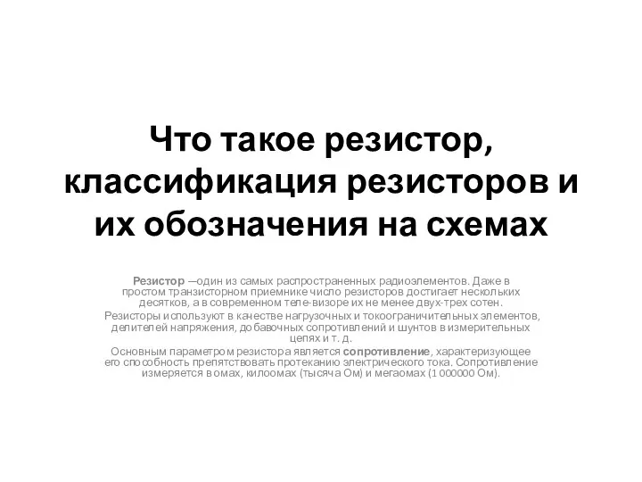 Классификация резисторов и их обозначения на схемах. (8 класс)
 Элементы оптоэлектроники. Приборы с зарядовой связью. Светодиоды. (Лекция 14.2)
 Метрология. Посадки подшипников качения
 Тормозная система Lada Priora
 Инерция. Галилео Галилей
 Экспериментальное крыло самолета ВАe 125
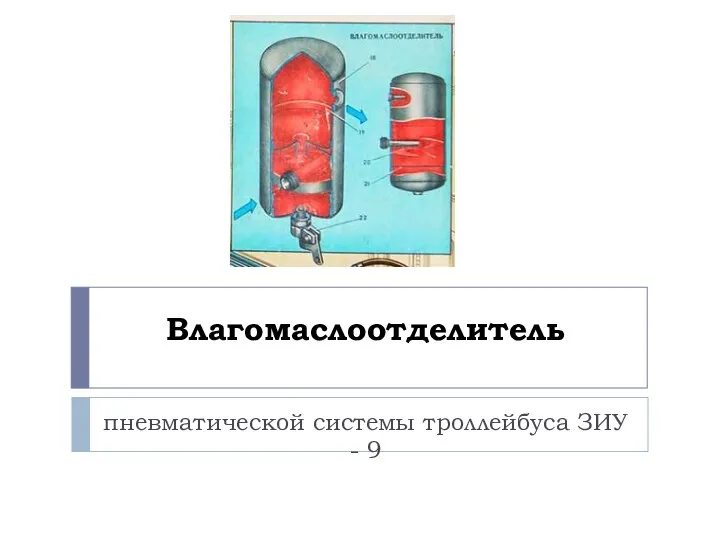 Влагомаслоотделитель пневматической системы троллейбуса ЗИУ - 9
 Електричний струм у газах
 Кристаллические и аморфные тела
 Искусственные алмазы
 Инфракрасные средства обнаружения
 Мощность и работа электрического тока
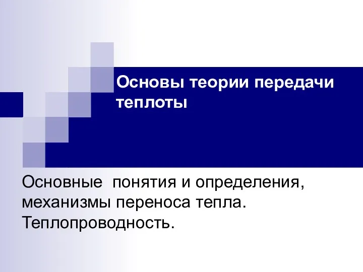 Основы теории передачи теплоты. Основные понятия и определения, механизмы переноса тепла. Теплопроводность
 Люминесцентный анализ
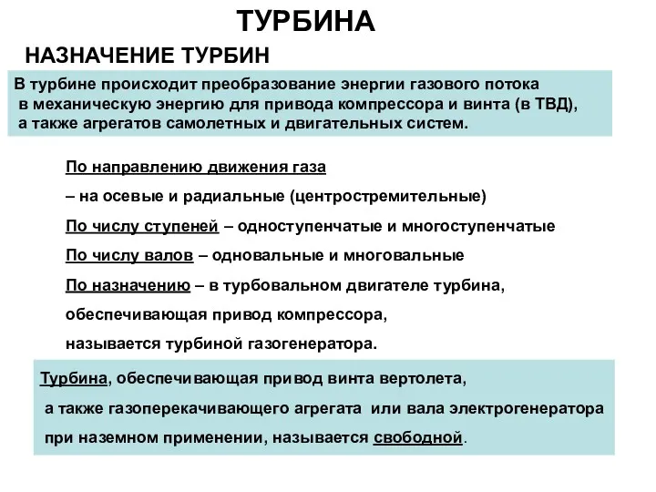 Турбина. Назначение турбин
 Сложное сопротивление
 Топливный насос высокого давления. Форсунки
 Электризация тел
 Ядерные реакции. Ядерная энергия
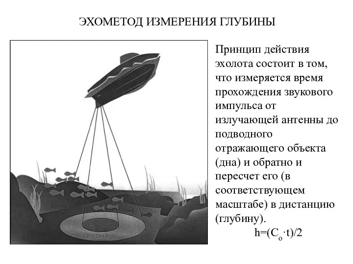 Эхометод измерения глубины
 Автомобили с управляемыми системами подрессоривания