- Inductance. Self-inductance

Содержание
- 2. Lecture 14 Inductance Self-inductance RL Circuits Energy in a Magnetic Field Mutual inductance LC circuit –
- 3. When the switch is thrown to its closed position, the current does not immediately jump from
- 4. (a) A current in the coil produces a magnetic field directed to the left. (b) If
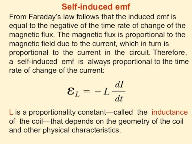
- 5. Self-induced emf From Faraday’s law follows that the induced emf is equal to the negative of
- 6. From last expression it follows that So inductance is a measure of the opposition to a
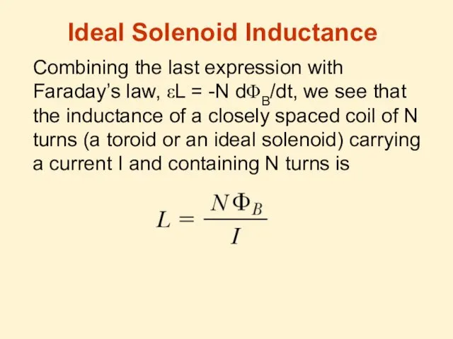
- 7. Ideal Solenoid Inductance Combining the last expression with Faraday’s law, εL = -N dΦB/dt, we see
- 8. An inductor in a circuit opposes changes in the current in that circuit: Series RL Circuit
- 10. Taking the antilogarithm of the last result: Because I = 0 at t = 0, we
- 11. The time constant τ is the time interval required for I to reach 0.632 (1-e-1) of
- 12. Multiplying by I the expression for RL–circuit we obtain: So here Iε is the power output
- 13. After integration of the last formula: L is the inductance of the inductor, I is the
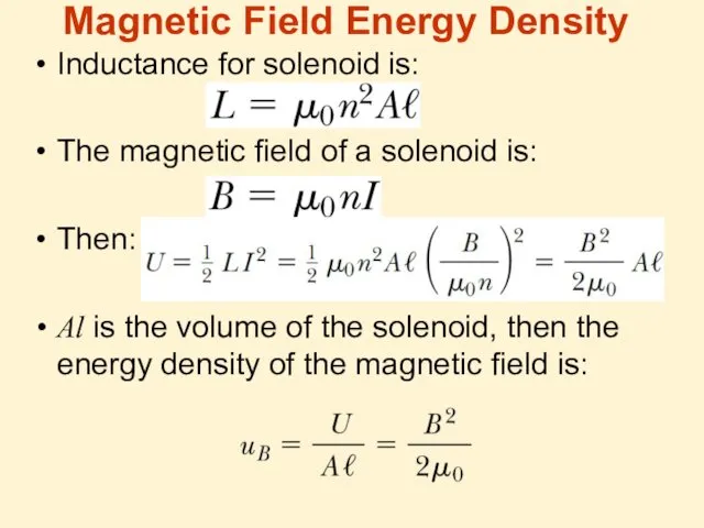
- 14. Inductance for solenoid is: The magnetic field of a solenoid is: Then: Al is the volume
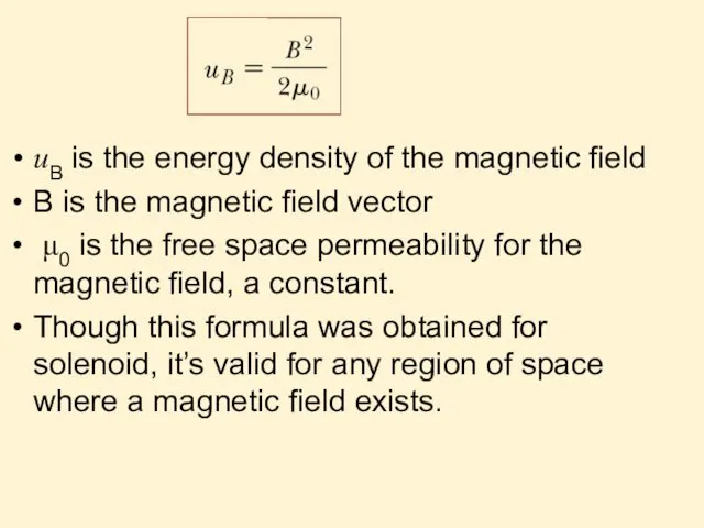
- 15. uB is the energy density of the magnetic field B is the magnetic field vector μ0
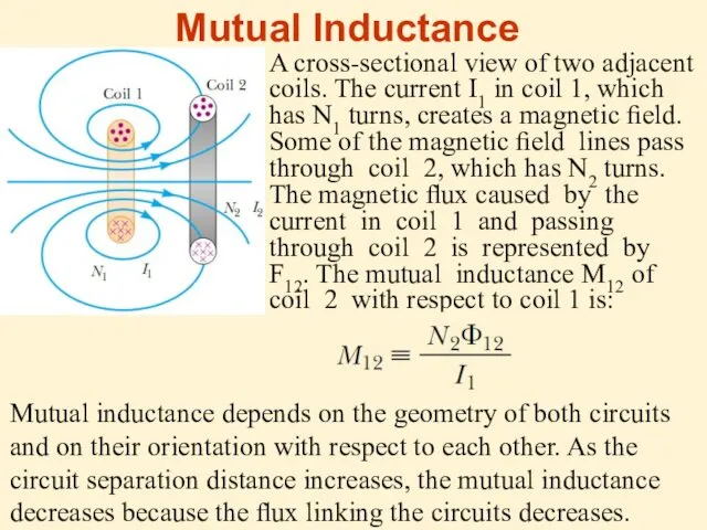
- 16. A cross-sectional view of two adjacent coils. The current I1 in coil 1, which has N1
- 17. Mutual inductance depends on the geometry of both circuits and on their orientation with respect to
- 18. The emf induced by coil 1 in coil 2 is: The preceding discussion can be repeated
- 19. Although the proportionality constants M12 and M21 have been obtained separately, it can be shown that
- 20. If the capacitor is initially charged and the switch is then closed, we find that both
- 22. The solution for the equation is: The angular frequency of the oscillations depends solely on the
- 23. Then the current is: Choosing the initial conditions: at t = 0, I = 0 and
- 24. Graph of charge versus time and Graph of current versus time for a resistanceless, nonradiating LC
- 25. Plots of UC versus t and UL versus t for a resistanceless, nonradiating LC circuit. The
- 26. A series RLC circuit. Switch S1 is closed and the capacitor is charged. S1 is then
- 27. Energy is dissipated on the resistor: Using the equation for dU/dt in the LC-circuit (slide 2):
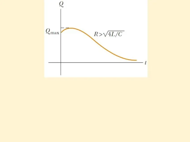
- 28. The RLC circuit is analogous to the damped harmonic oscillator, where R is damping coefficient. Here
- 32. Скачать презентацию
Lecture 14
Inductance
Self-inductance
RL Circuits
Energy in a Magnetic Field
Mutual inductance
LC circuit – harmonic
Lecture 14
Inductance
Self-inductance
RL Circuits
Energy in a Magnetic Field
Mutual inductance
LC circuit – harmonic
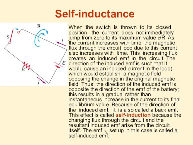
When the switch is thrown to its closed position, the current
When the switch is thrown to its closed position, the current
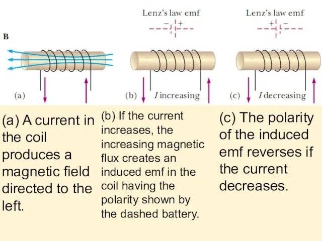
(a) A current in the coil produces a magnetic field directed
(a) A current in the coil produces a magnetic field directed
Self-induced emf
From Faraday’s law follows that the induced emf is equal
Self-induced emf
From Faraday’s law follows that the induced emf is equal
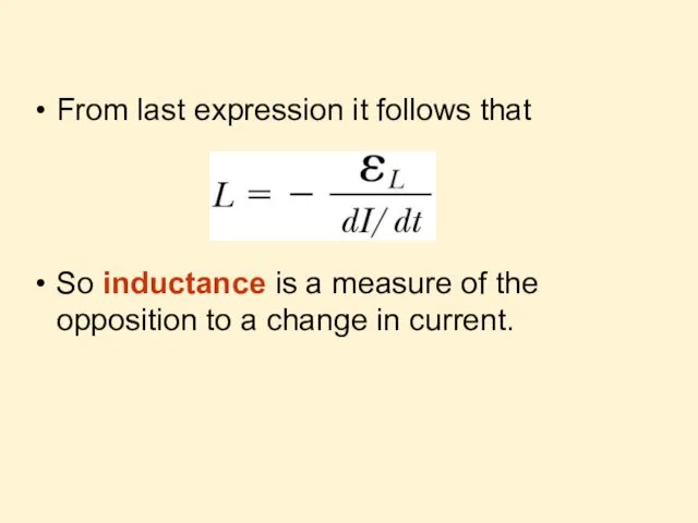
From last expression it follows that
So inductance is a measure of
From last expression it follows that
So inductance is a measure of
Ideal Solenoid Inductance
Combining the last expression with Faraday’s law, εL =
Ideal Solenoid Inductance
Combining the last expression with Faraday’s law, εL =
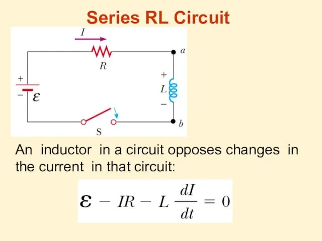
An inductor in a circuit opposes changes in the current in
An inductor in a circuit opposes changes in the current in
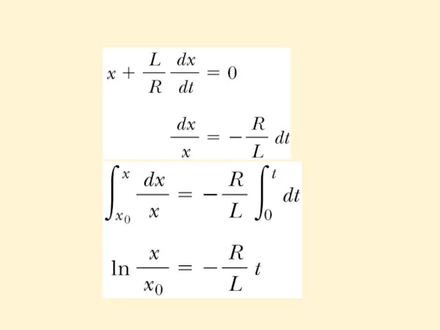
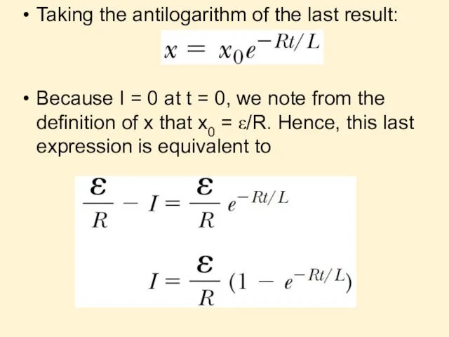
Taking the antilogarithm of the last result:
Because I = 0 at
Taking the antilogarithm of the last result:
Because I = 0 at
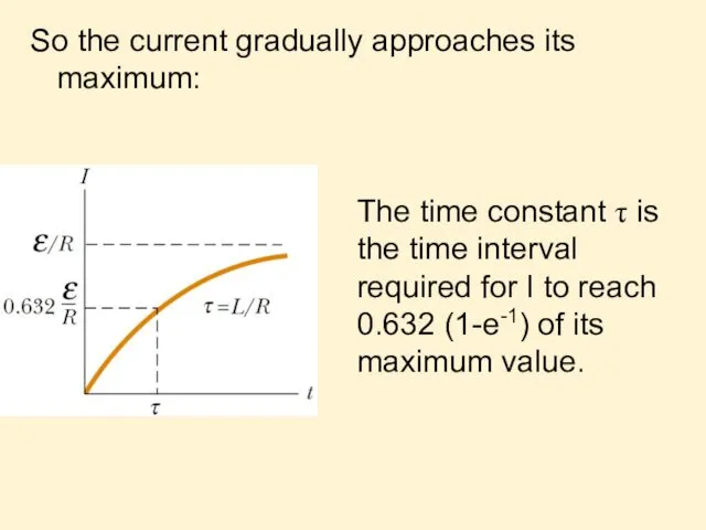
The time constant τ is the time interval required for I
The time constant τ is the time interval required for I
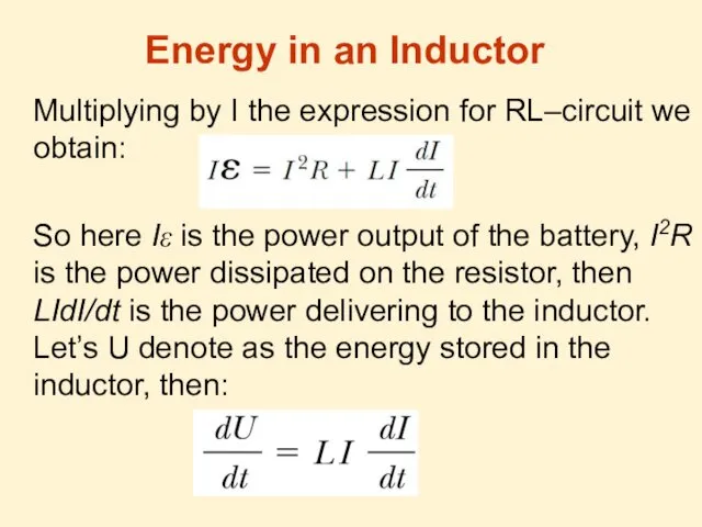
Multiplying by I the expression for RL–circuit we obtain:
So here Iε
Multiplying by I the expression for RL–circuit we obtain:
So here Iε
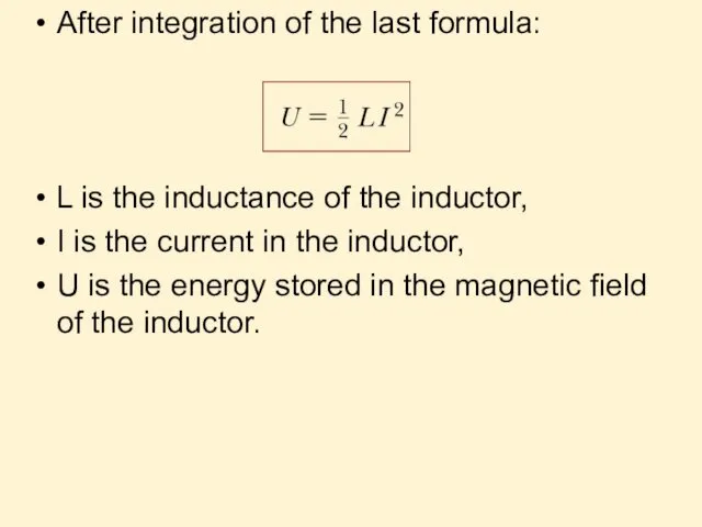
After integration of the last formula:
L is the inductance of the
After integration of the last formula:
L is the inductance of the
Inductance for solenoid is:
The magnetic field of a solenoid is:
Then:
Al is
Inductance for solenoid is:
The magnetic field of a solenoid is:
Then:
Al is
uB is the energy density of the magnetic field
B is the
uB is the energy density of the magnetic field
B is the
A cross-sectional view of two adjacent coils. The current I1 in
A cross-sectional view of two adjacent coils. The current I1 in
Mutual inductance depends on the geometry of both circuits and on
Mutual inductance depends on the geometry of both circuits and on
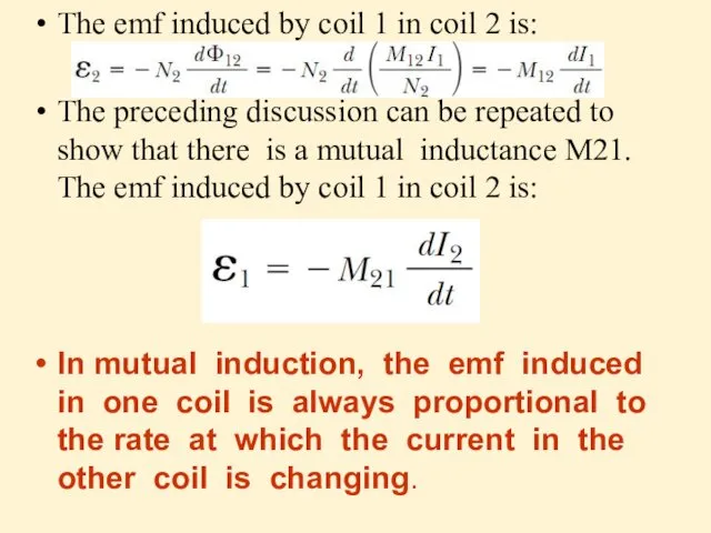
The emf induced by coil 1 in coil 2 is:
The preceding
The emf induced by coil 1 in coil 2 is:
The preceding
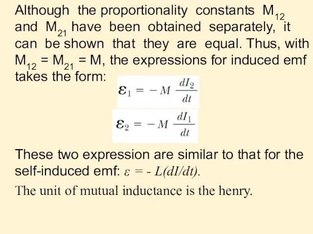
Although the proportionality constants M12 and M21 have been obtained separately,
Although the proportionality constants M12 and M21 have been obtained separately,
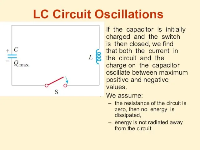
If the capacitor is initially charged and the switch is then
If the capacitor is initially charged and the switch is then

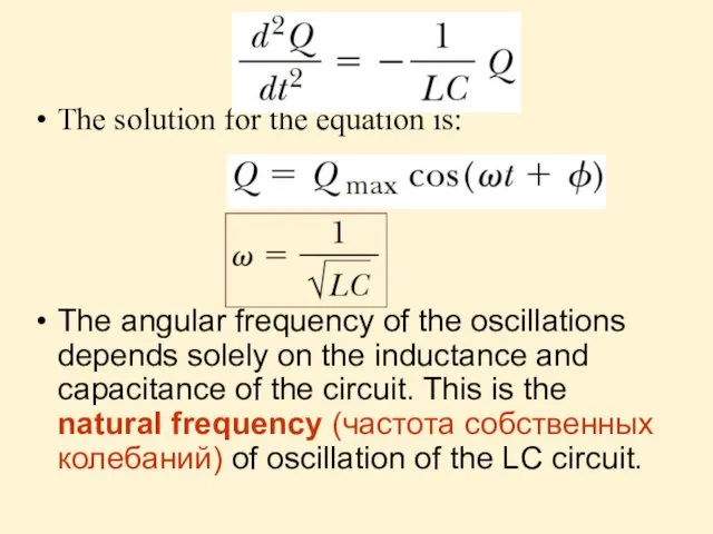
The solution for the equation is:
The angular frequency of the
The angular frequency of the
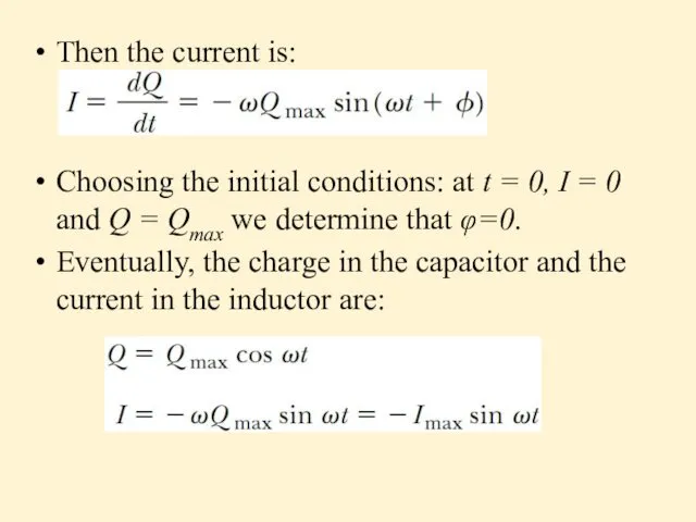
Then the current is:
Choosing the initial conditions: at t = 0,
Then the current is:
Choosing the initial conditions: at t = 0,
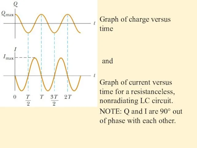
Graph of charge versus time
and
Graph of current versus time for
and
Graph of current versus time for
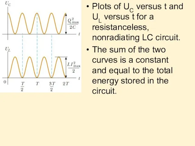
Plots of UC versus t and UL versus t for a
Plots of UC versus t and UL versus t for a
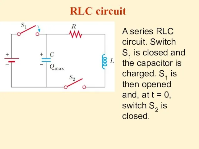
A series RLC circuit. Switch S1 is closed and the capacitor
A series RLC circuit. Switch S1 is closed and the capacitor
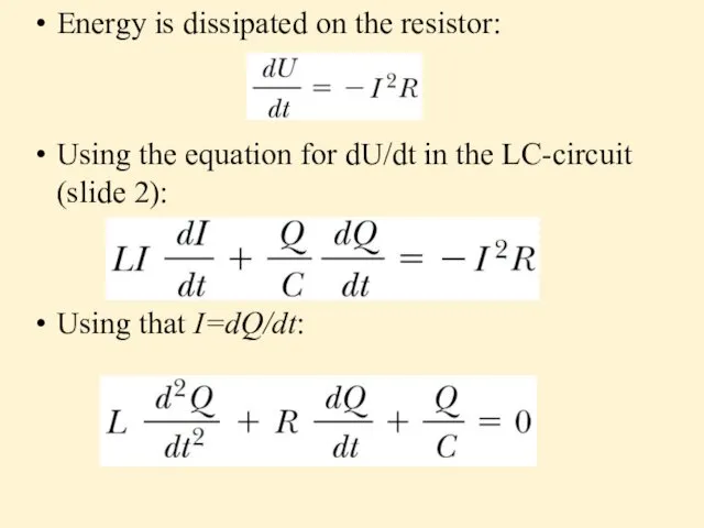
Energy is dissipated on the resistor:
Using the equation for dU/dt in
Energy is dissipated on the resistor:
Using the equation for dU/dt in
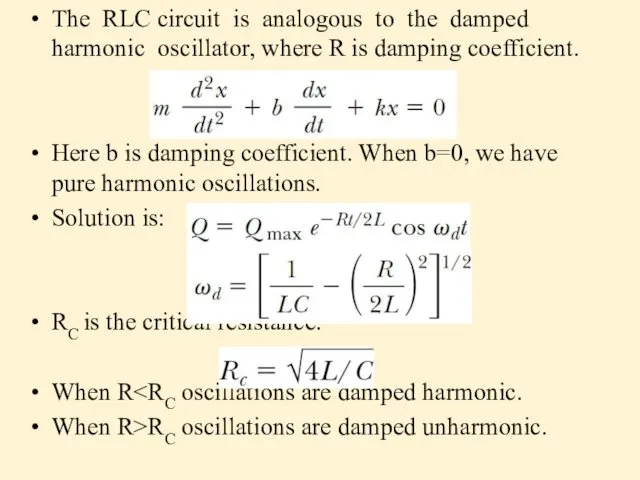
The RLC circuit is analogous to the damped harmonic oscillator, where
The RLC circuit is analogous to the damped harmonic oscillator, where

 Паровая турбина. КПД теплового двигателя
 Зубчатая передача электровоза ВЛ85
 Электризация тел. Два рода зарядов
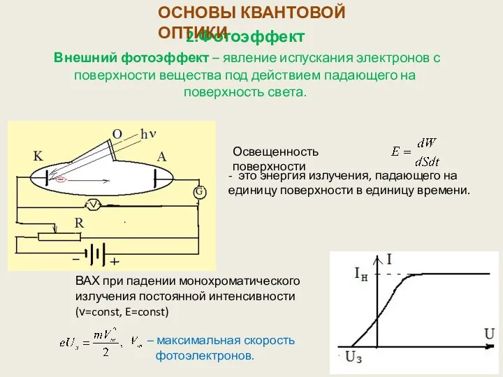 Основы квантовой оптики. Фотоэффект
 Физические свойства зерна
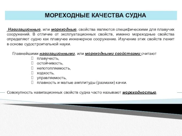 Мореходные качества судна
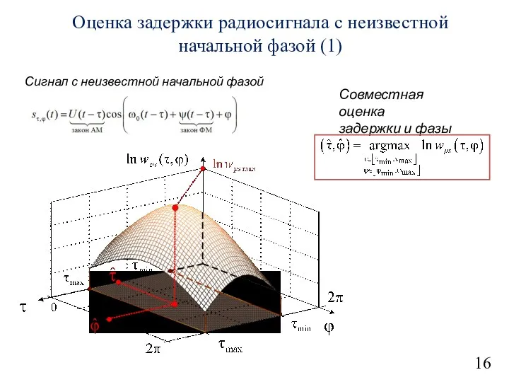 Оценка задержки радиосигнала с неизвестной начальной фазой
 Презентация по физике в 11 классе по теме Физическая природа планет солнечной системы. Уран.
 Техногенные опасности. Статическое электричество. Лазерное излучение
 Механическая мощность. Физика 7 класс
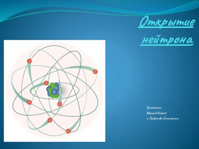 Открытие нейтрона
 Кинематика движения материальной точки
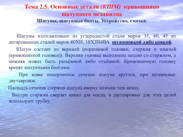 Основные детали (КШМ) кривошипно шатунного механизма. Устройство, смазка. Тема 2.5. Урок 10
 Эл. ток в металлах. Действие и направление эл. тока 8 класс
 Строение атома
 Электрический ток и его использование (8 класс)
 Первый закон Ньютона
 Электромагнитная картина мира
 Конструкция автомобиля. Сцепление
 ФИЗИКА 8 класс Изменение агрегатных состояний вещества
 Основные положения спектроскопии
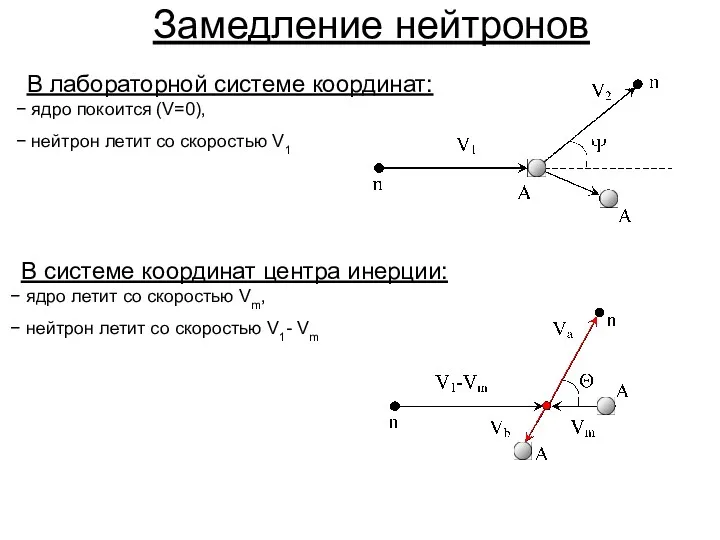 Замедление нейтронов
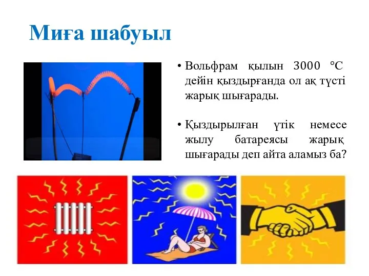 Миға шабуыл. Кванттық физика. Жылулық сәулелену
 Урок по физике на тему:Инерция и инертность
 Состав ядра. Ядерные силы
 Динамика. Законы Ньютона
 Функціональні матеріали для високоенергетичної електроніки
 Физические основы магнитопорошкового метода контроля