- Operators 413/415. Electromechanical operators for swing gates

Содержание
- 2. OPERATOR 413
- 3. TECHNICAL SPECIFICATIONS Operator with “OFF-AXIS” thrust Available in versions 230V and 24V Available in versions with
- 4. Release device –key protected and easy to operate Numbered locks 1-36 (optional) OPERATOR 413
- 5. Limit switch 24 Vdc power supplied to guarantee the highest security Possibility for management of “stops”
- 6. Horizontal cable exit for installations close to the ground Predisposition for the use of the “Gatecoder”
- 7. RANGE 413
- 8. OPERATOR 415
- 9. TECHNICAL SPECIFICATIONS Operator with “IN-AXIS” thrust Available in versions 230V and 24V Available in versions with
- 10. Horizontal cable exit for installations close to the ground Predisposition for the use of the “Gatecoder”
- 11. OPERATOR 415 (with carter optional)
- 12. Release device –key protected and easy to operate Numbered locks 1-36 (optional) OPERATOR 415
- 13. Limit switch 24 Vdc power supplied to guarantee the highest security Possibility for management of “stops”
- 14. Horizontal cable exit for installations close to the ground Predisposition for the use of the “Gatecoder”
- 15. RANGE 415
- 16. TECHNICAL REPORT SWING GATE OPERATOR ANALYSIS AMI A180 ATI A3000
- 17. vs 413 CAME BX-A 1) See the test results AMI A180
- 18. AMI A180
- 19. PROTECTION CLASS IP
- 20. Connection terminal board Stator Limit switch power supply 230V PROTECTION IP
- 21. Very few protection of the reduction gearing due to type of cover and lack of joints
- 22. Electric limit switch only in opening, INTERFERES IN THE MOTOR PHASE, PROTECTION CLASS IP20. In the
- 23. The worm screw is made of “normal” steel and protected only by a burnishing treatment (normally
- 24. Functioning test executed on gate LP001 2m leaf weight kg. 360 Start test 23-09-04 End of
- 25. vs 415 CAME BX-A 1) See the test results ATI A3000
- 26. AMI A3000 AMI A5000
- 27. NB.: no models available with mechanical stops ANALYSIS TECHNICAL SPECIFICATIONS
- 28. PROTECTION IP
- 29. Concept and matching of the carter imply low protection of the complete reduction group. H2O IP
- 30. The normative requires expressly that “the apparatus needs to be provided with fixing devices for the
- 31. MOTION TRANSMISSION BETWEEN ROTOR AND EPICYCLOIDAL REDUCTION Motion transmission between rotor e epicycloidal reduction through plastic
- 32. Epicycloidal reduction, locking system through electro brake. The electrobrake keeps the rotor stopped by friction, therefore
- 33. The motor lock is given by the electric brake acting on the rotor, while the release
- 34. ELECTRIC LIMIT SWITCH Electric limit switch in version 230V INTERFERES ON THE MOTOR PHASE, PROTECTION CLASS
- 35. REGULATION OF THE ELECTRIC END TRAVELS In order to regulate the electric limit switches, it is
- 36. WORM SCREW The worm screw is made of “normal” steel and protected only by a burnishing
- 37. The screw covering solution, although it does not guarantee an efficient protection against screw oxidation, can
- 38. Execution test of functioning on gate LP011 with 4m leaf and weight kg. 250 Start 1°
- 39. TECHNICAL REPORT SWING GATE OPERATOR ANALYSIS PLUTO PL4005 MOBY 4006 WINGOKIT
- 40. MOBY
- 41. vs 415 CAME BX-A 1) See the test results MOBY MB4005
- 42. Max. leaf for serie 5000 with max. length m 3,75 For leaf max.m. 5: in order
- 43. H2O entrance H2O entrance H2O entrance H2O entrance PROTECTION IP
- 44. The Moby model range exists only in version with electric limit switches, BY INTERRUPTING THE PHASE,
- 45. The “exclusive” Nice release is certainly easy to operate, but unfortunately it remains in up position
- 46. • Worm screw in normal steel and grease as only protection (Contrary to the FAAC screws
- 47. Execution of functioning test on gate LP011 with leaf m 2,50 and weight kg. 200 Start
- 48. Entrata H2O Entrata H2O Entrata H2O Entrata H2O PROTECTION OF THE INTERNAL MECHANICS
- 49. The worm screw is in normal steel and the protection is guaranteed only by the grease
- 50. The “exclusive” Nice release is certainly easy to operate, but unfortunately it remains in up position
- 51. WINGO
- 52. vs 413 CAME BX-A 1) See the test results WINGOKIT
- 53. Remark : Among the use restrictions with leaf weight and leaf length has been indicated that
- 54. Entrance H2O Protection class IP42, please see the water signs in the motor cable area To
- 55. H2O entrance H2O entrance H2O entrance PROTECTION IP
- 56. The worm screw is in normal steel and the protection is guaranteed only by the grease
- 57. The cable connection is situated in the area of the fixation pin on the bracket without
- 58. The “exclusive” Nice release is certainly easy to operate, but unfortunately it remains in up position
- 59. NB. The water you see inside entered with closed release. The plastic carter protection is useless
- 61. Скачать презентацию
 Виды излучений
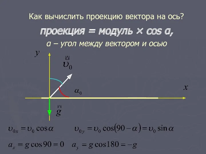 Как вычислить проекцию?
 Спутниковые системы связи
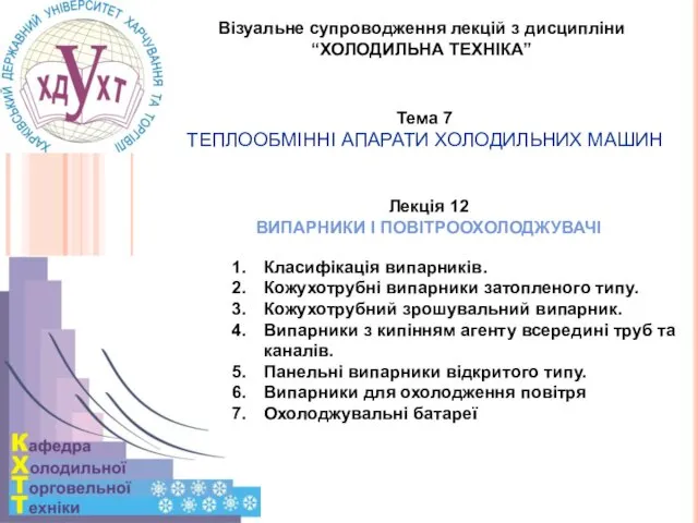 Випарники і повітроохолоджувачі
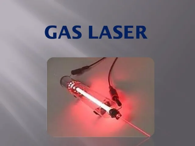 Gas laser
 Расчет количества теплоты необходимого для нагревания тела или выделяемого им при охлаждении. Решение задач. Физика. 8 класс
 Рентгеновское излучение
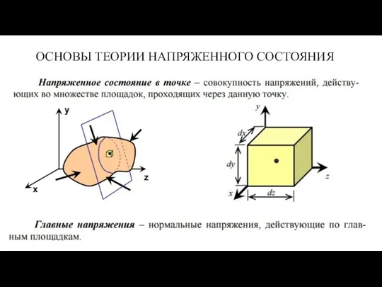 Основы теории напряженного состояния
 Физические величины. 10 класс
 Закон всемирного тяготения
 Закон Ома. Тест
 Э.М. Спиридонов. Эволюция минералов серебра в зоне гипергенеза
 Контроль параметрів радіовипромінювання. Радіоперешкоди
 Передача и использование электрической энергии
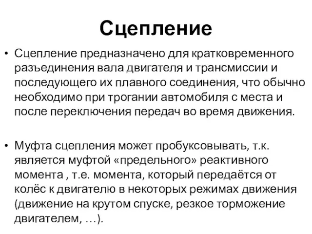 Сцепление. Требования к сцеплению
 Закон всесвітнього тяжіння. Розв’язання задач
 Презентация Силы в природе
 Электрический ток в различных средах
 Лекция №3 (3 ). Волновые уравнения электродинамики
 Элементарные частицы
 Жарықтандыру және дабылдау
 Урок физики 7 класс Применение простых механизмов
 Электростатика
 Методическая разработка Проблемное обучение в преподавании физики
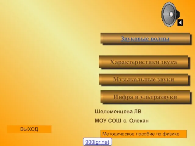 В мире звуков
 Простые механизмы. Рычаг
 Токарно-винторезный станок мод. 16К20
 Урок-путешествие. Электричество 8 класс