- Overhaul Daikin screw compressor

Содержание
- 2. Calant wim Oil drainage Two oil drain plugs For fast oil drainage break the sealing of
- 3. Calant wim Remove side cover, use guiding bolts to support the side cover
- 4. Calant wim Removing gate rotor Remove top cover gate rotor
- 5. Calant wim Removing gate rotor Remove the gate rotor bearing retaining plate, remove the two M4
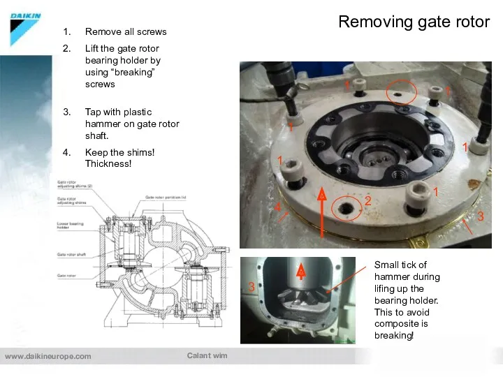
- 6. Calant wim Removing gate rotor Remove all screws Lift the gate rotor bearing holder by using
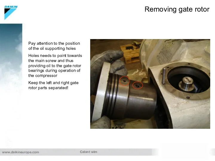
- 7. Calant wim Removing gate rotor Pay attention to the position of the oil supporting holes Holes
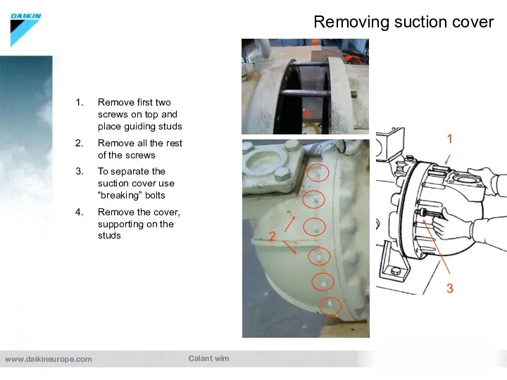
- 8. Calant wim Removing suction cover Remove first two screws on top and place guiding studs Remove
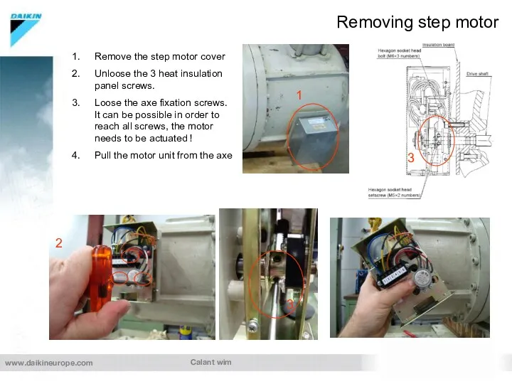
- 9. Calant wim Removing step motor Remove the step motor cover Unloose the 3 heat insulation panel
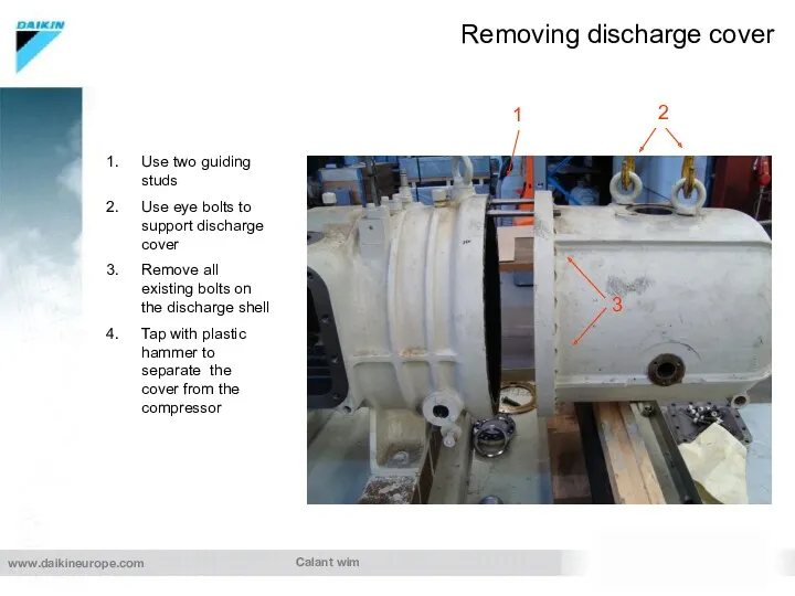
- 10. Calant wim Removing discharge cover Use two guiding studs Use eye bolts to support discharge cover
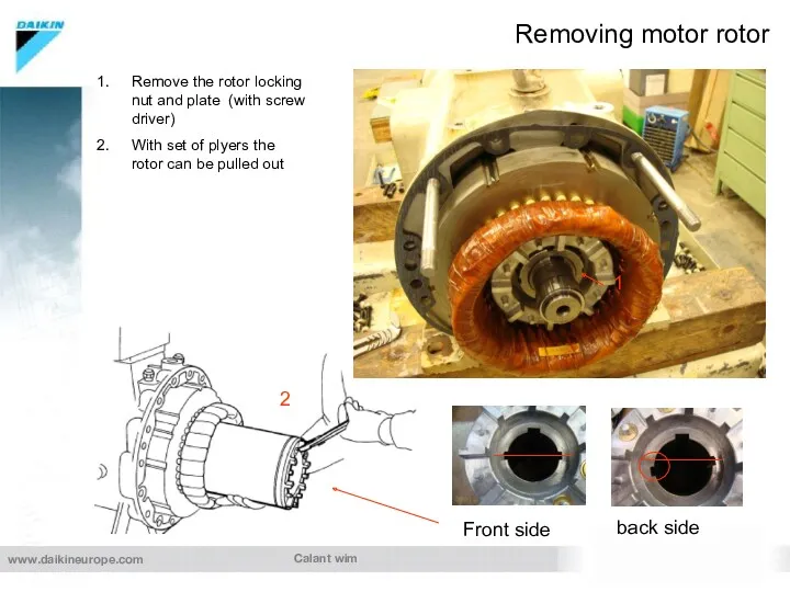
- 11. Calant wim Removing motor rotor Remove the rotor locking nut and plate (with screw driver) With
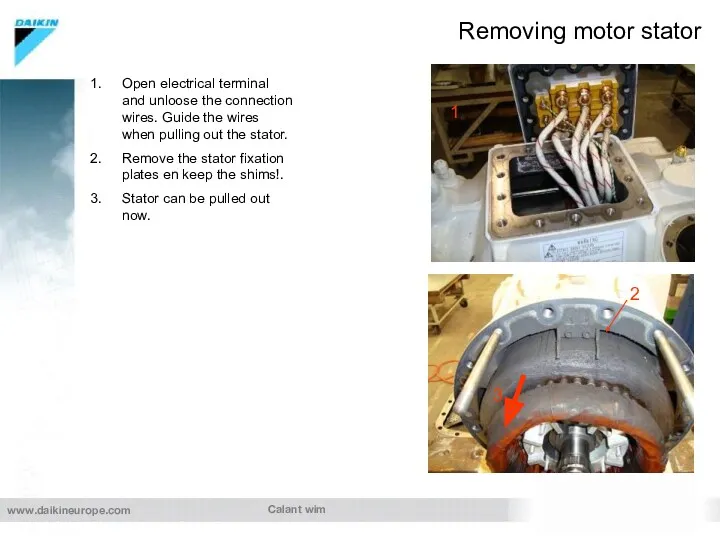
- 12. Calant wim Removing motor stator Open electrical terminal and unloose the connection wires. Guide the wires
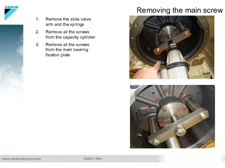
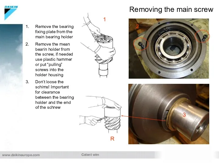
- 13. Calant wim Removing the main screw Remove the slide valve arm and the springs Remove all
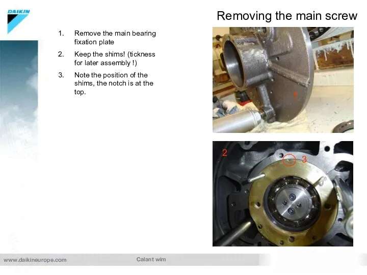
- 14. Calant wim Removing the main screw Remove the main bearing fixation plate Keep the shims! (tickness
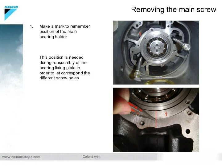
- 15. Calant wim Removing the main screw Make a mark to remember position of the main bearing
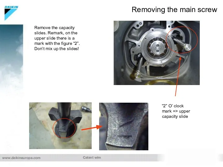
- 16. Calant wim Removing the main screw “2” O’ clock mark => upper capacity slide Remove the
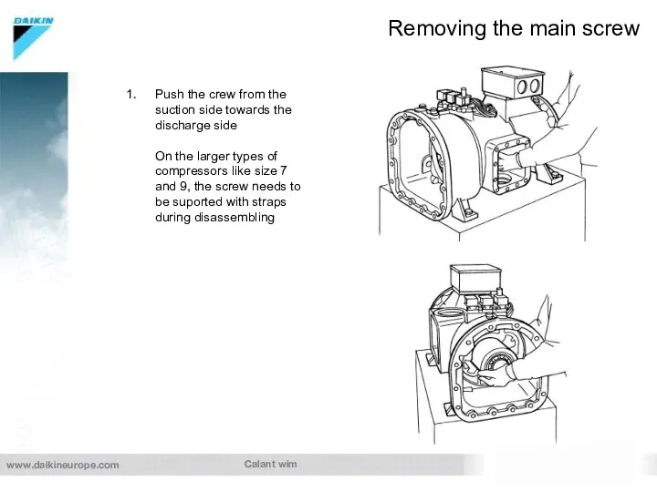
- 17. Calant wim Removing the main screw Push the crew from the suction side towards the discharge
- 18. Calant wim Removing the main screw Remove the bearing fixing plate from the main bearing holder
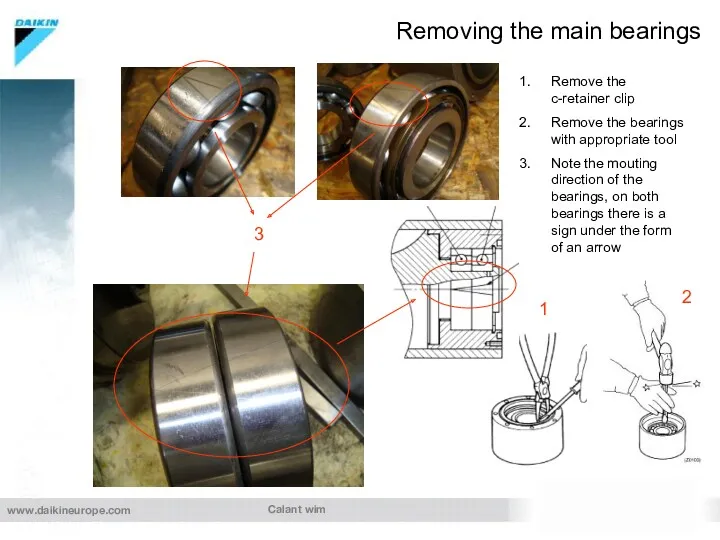
- 19. Calant wim Removing the main bearings Remove the c-retainer clip Remove the bearings with appropriate tool
- 20. Calant Wim Overhaul Daikin screw compressor important issues during assembling of the Daikin G/F type compressor
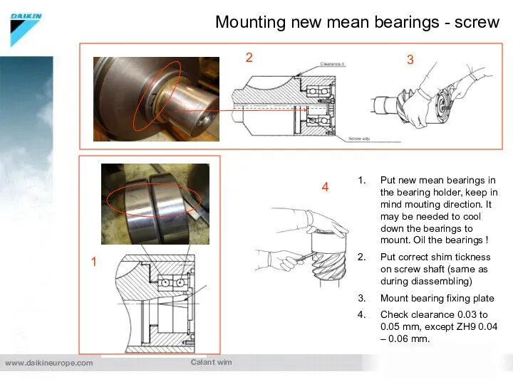
- 21. Calant wim Put new mean bearings in the bearing holder, keep in mind mouting direction. It
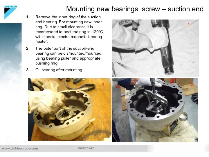
- 22. Calant wim Mounting new bearings screw – suction end Remove the inner ring of the suction
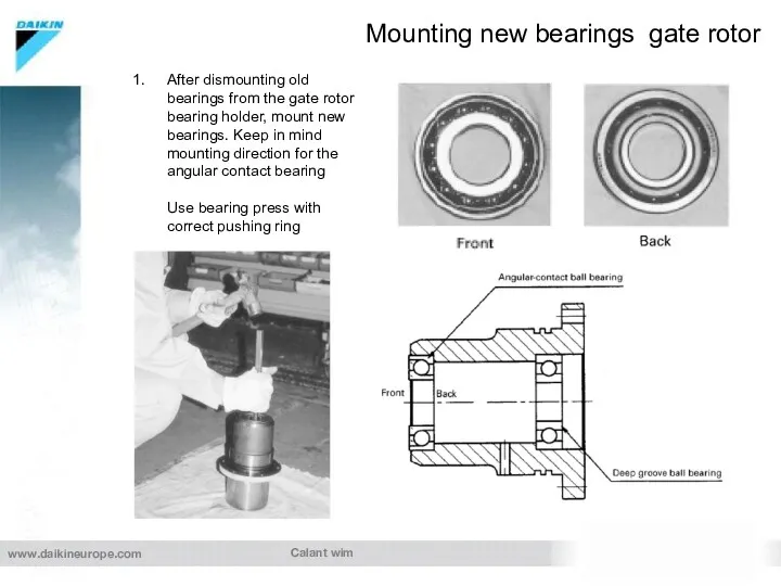
- 23. Calant wim Mounting new bearings gate rotor After dismounting old bearings from the gate rotor bearing
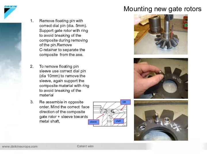
- 24. Calant wim Mounting new gate rotors Remove floating pin with correct dial pin (dia. 5mm). Support
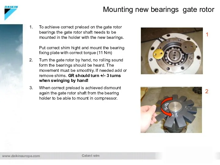
- 25. Calant wim Mounting new bearings gate rotor To achieve correct preload on the gate rotor bearings
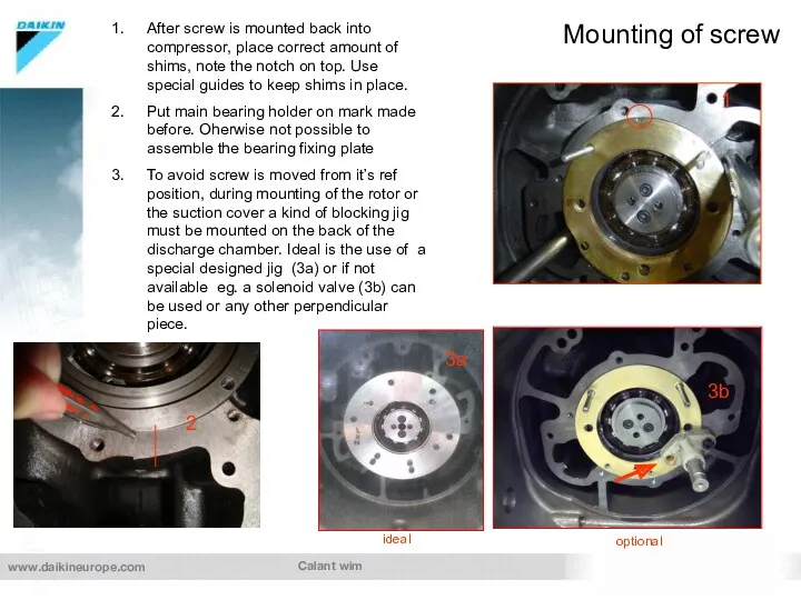
- 26. Calant wim Mounting of screw After screw is mounted back into compressor, place correct amount of
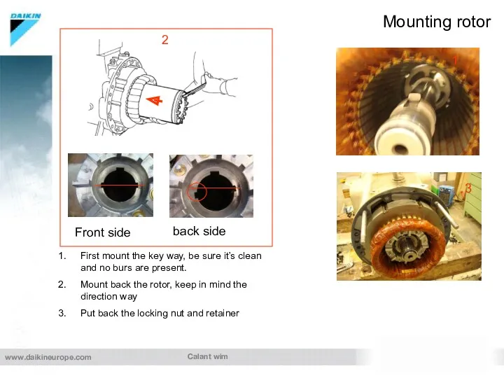
- 27. Calant wim Mounting rotor Front side back side First mount the key way, be sure it’s
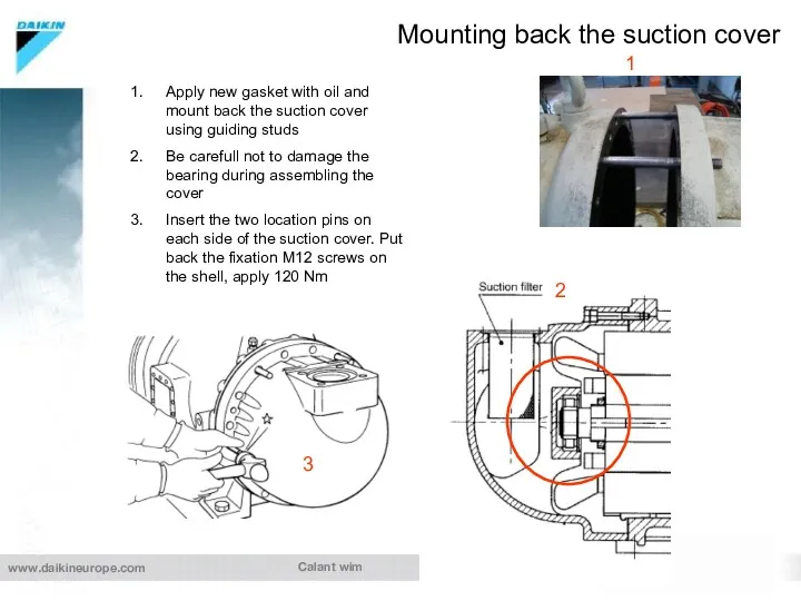
- 28. Calant wim Mounting back the suction cover 1 Apply new gasket with oil and mount back
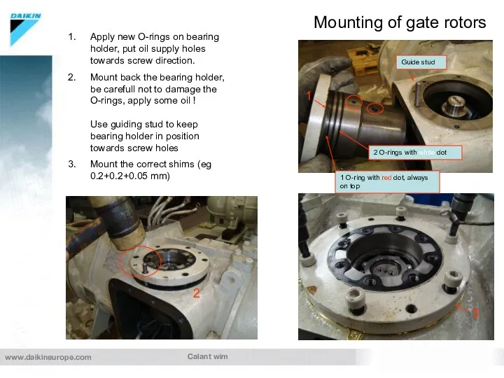
- 29. Calant wim Mounting of gate rotors Apply new O-rings on bearing holder, put oil supply holes
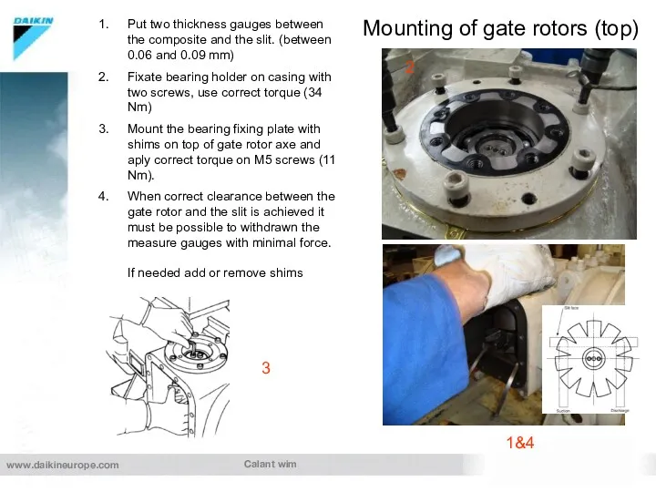
- 30. Calant wim Mounting of gate rotors (top) Put two thickness gauges between the composite and the
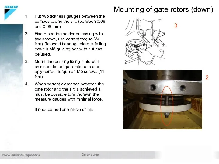
- 31. Calant wim Mounting of gate rotors (down) Put two tickness gauges between the composite and the
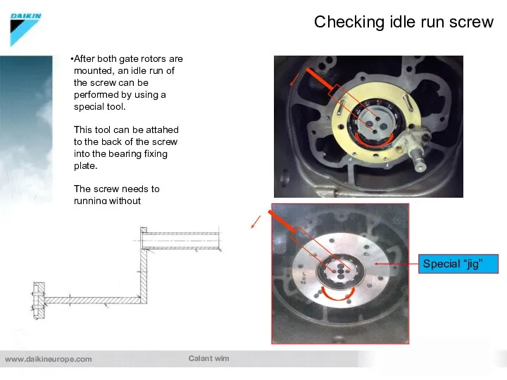
- 32. Calant wim Checking idle run screw After both gate rotors are mounted, an idle run of
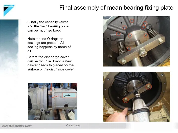
- 33. Calant wim Final assembly of mean bearing fixing plate Finally the capacity valves and the main
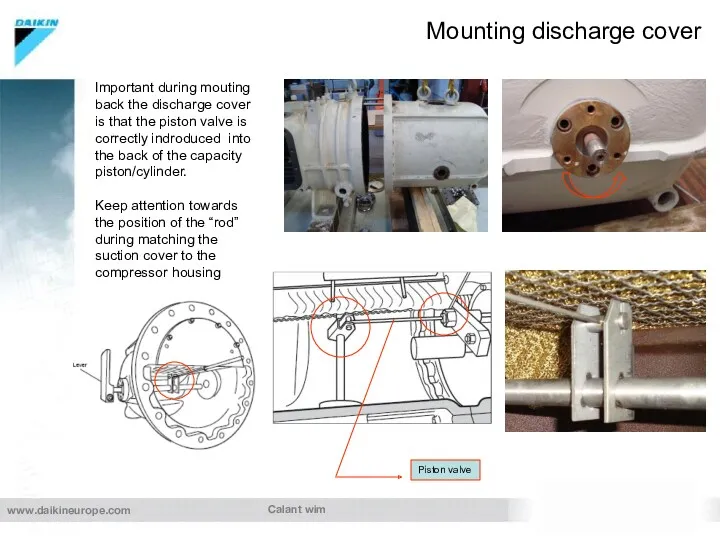
- 34. Calant wim Mounting discharge cover Important during mouting back the discharge cover is that the piston
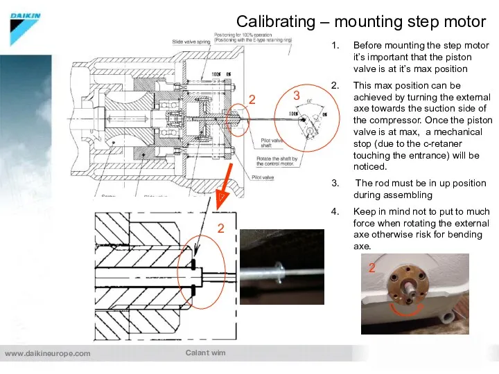
- 35. Calant wim Calibrating – mounting step motor Before mounting the step motor it’s important that the
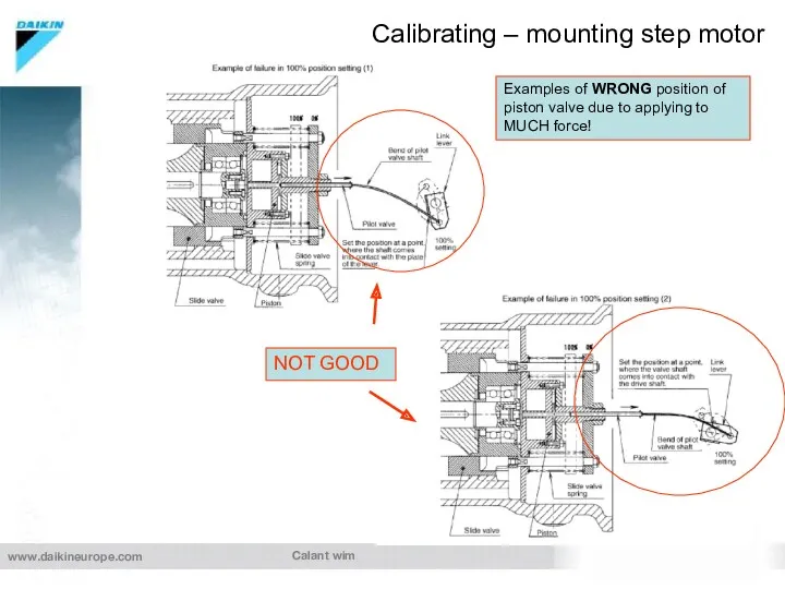
- 36. Calant wim Calibrating – mounting step motor Examples of WRONG position of piston valve due to
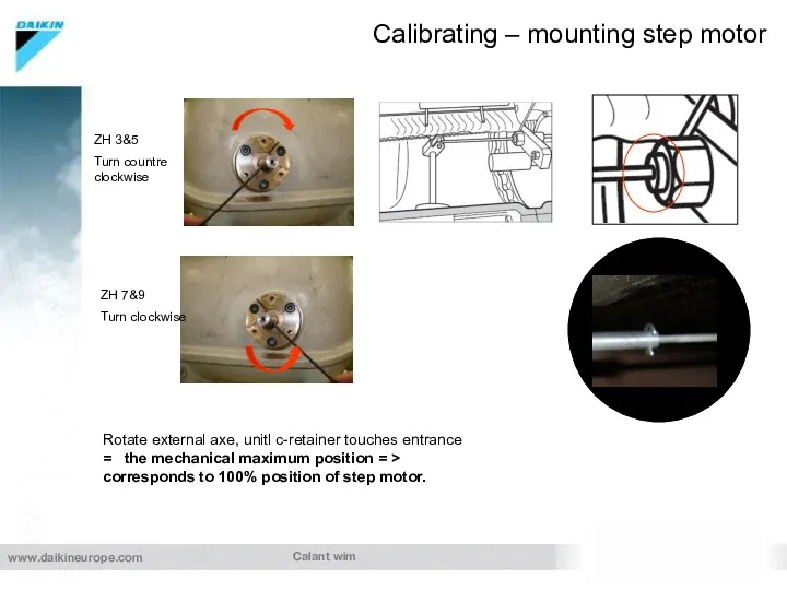
- 37. Calant wim Calibrating – mounting step motor Rotate external axe, unitl c-retainer touches entrance = the
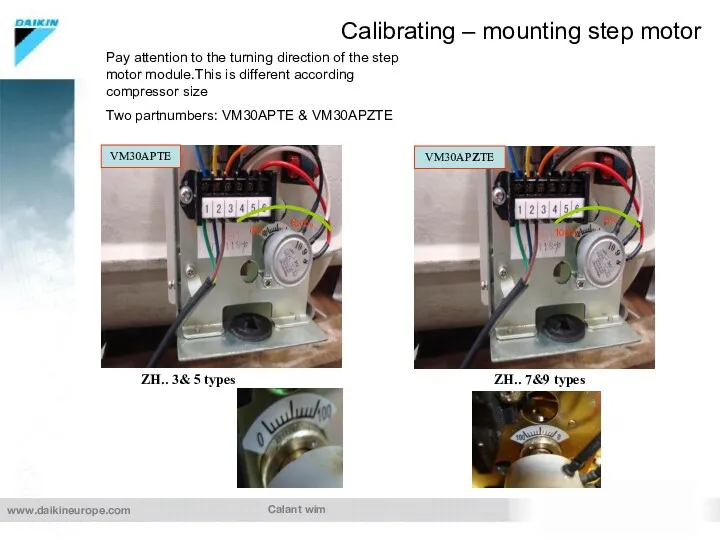
- 38. Calant wim Calibrating – mounting step motor ZH.. 3& 5 types ZH.. 7&9 types VM30APTE VM30APZTE
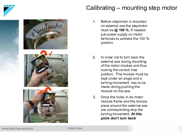
- 39. Calant wim Calibrating – mounting step motor Before stepmotor is mounted on external axe the stepmotor
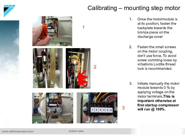
- 40. Calant wim Calibrating – mounting step motor Once the motormodule is at its position, fasten the
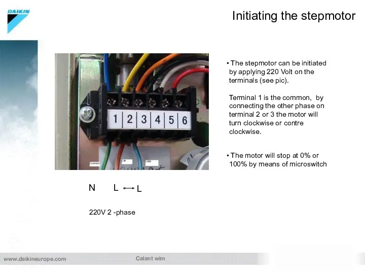
- 41. Calant wim Initiating the stepmotor 220V 2 -phase N L L The stepmotor can be initiated
- 43. Скачать презентацию
Calant wim
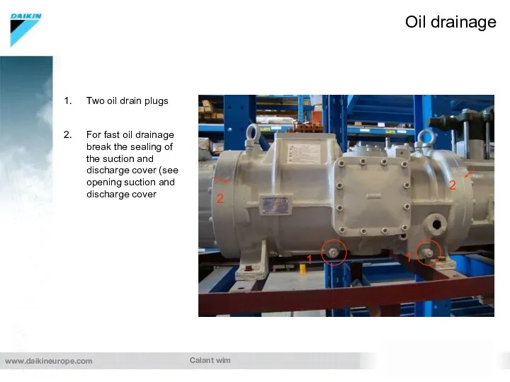
Oil drainage
Two oil drain plugs
For fast oil drainage break the
Calant wim
Oil drainage
Two oil drain plugs
For fast oil drainage break the
Calant wim
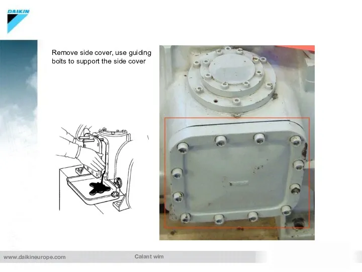
Remove side cover, use guiding bolts to support the side
Calant wim
Remove side cover, use guiding bolts to support the side
Calant wim
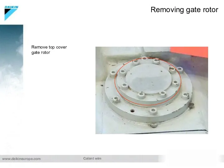
Removing gate rotor
Remove top cover gate rotor
Calant wim
Removing gate rotor
Remove top cover gate rotor
Calant wim
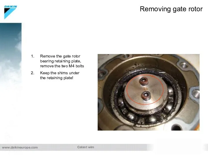
Removing gate rotor
Remove the gate rotor bearing retaining plate, remove
Calant wim
Removing gate rotor
Remove the gate rotor bearing retaining plate, remove
Calant wim
Removing gate rotor
Remove all screws
Lift the gate rotor bearing holder
Calant wim
Removing gate rotor
Remove all screws
Lift the gate rotor bearing holder
Calant wim
Removing gate rotor
Pay attention to the position of the oil
Calant wim
Removing gate rotor
Pay attention to the position of the oil
Calant wim
Removing suction cover
Remove first two screws on top and place
Calant wim
Removing suction cover
Remove first two screws on top and place
Calant wim
Removing step motor
Remove the step motor cover
Unloose the 3 heat
Calant wim
Removing step motor
Remove the step motor cover
Unloose the 3 heat
Calant wim
Removing discharge cover
Use two guiding studs
Use eye bolts to support
Calant wim
Removing discharge cover
Use two guiding studs
Use eye bolts to support
Calant wim
Removing motor rotor
Remove the rotor locking nut and plate (with
Calant wim
Removing motor rotor
Remove the rotor locking nut and plate (with
Calant wim
Removing motor stator
Open electrical terminal and unloose the connection wires.
Calant wim
Removing motor stator
Open electrical terminal and unloose the connection wires.
Calant wim
Removing the main screw
Remove the slide valve arm and the
Calant wim
Removing the main screw
Remove the slide valve arm and the
Calant wim
Removing the main screw
Remove the main bearing fixation plate
Keep the
Calant wim
Removing the main screw
Remove the main bearing fixation plate
Keep the
Calant wim
Removing the main screw
Make a mark to remember position of
Calant wim
Removing the main screw
Make a mark to remember position of
Calant wim
Removing the main screw
“2” O’ clock mark => upper capacity
Calant wim
Removing the main screw
“2” O’ clock mark => upper capacity
Calant wim
Removing the main screw
Push the crew from the suction side
Calant wim
Removing the main screw
Push the crew from the suction side
Calant wim
Removing the main screw
Remove the bearing fixing plate from the
Calant wim
Removing the main screw
Remove the bearing fixing plate from the
Calant wim
Removing the main bearings
Remove the c-retainer clip
Remove the bearings with
Calant wim
Removing the main bearings
Remove the c-retainer clip
Remove the bearings with
Calant Wim
Overhaul Daikin screw compressor
important issues during assembling of the Daikin
Calant Wim
Overhaul Daikin screw compressor
important issues during assembling of the Daikin
Calant wim
Put new mean bearings in the bearing holder, keep in
Calant wim
Put new mean bearings in the bearing holder, keep in
Calant wim
Mounting new bearings screw – suction end
Remove the inner ring
Calant wim
Mounting new bearings screw – suction end
Remove the inner ring
Calant wim
Mounting new bearings gate rotor
After dismounting old bearings from
Calant wim
Mounting new bearings gate rotor
After dismounting old bearings from
Calant wim
Mounting new gate rotors
Remove floating pin with correct dial pin
Calant wim
Mounting new gate rotors
Remove floating pin with correct dial pin
Calant wim
Mounting new bearings gate rotor
To achieve correct preload on the
Calant wim
Mounting new bearings gate rotor
To achieve correct preload on the
Calant wim
Mounting of screw
After screw is mounted back into compressor, place
Calant wim
Mounting of screw
After screw is mounted back into compressor, place
Calant wim
Mounting rotor
Front side
back side
First mount the key way, be sure
Calant wim
Mounting rotor
Front side
back side
First mount the key way, be sure
Calant wim
Mounting back the suction cover
1
Apply new gasket with oil and
Calant wim
Mounting back the suction cover
1
Apply new gasket with oil and
Calant wim
Mounting of gate rotors
Apply new O-rings on bearing holder, put
Calant wim
Mounting of gate rotors
Apply new O-rings on bearing holder, put
Calant wim
Mounting of gate rotors (top)
Put two thickness gauges between the
Calant wim
Mounting of gate rotors (top)
Put two thickness gauges between the
Calant wim
Mounting of gate rotors (down)
Put two tickness gauges between the
Calant wim
Mounting of gate rotors (down)
Put two tickness gauges between the
Calant wim
Checking idle run screw
After both gate rotors are mounted, an
Calant wim
Checking idle run screw
After both gate rotors are mounted, an
Calant wim
Final assembly of mean bearing fixing plate
Finally the capacity
Calant wim
Final assembly of mean bearing fixing plate
Finally the capacity
Calant wim
Mounting discharge cover
Important during mouting back the discharge cover is
Calant wim
Mounting discharge cover
Important during mouting back the discharge cover is
Calant wim
Calibrating – mounting step motor
Before mounting the step motor it’s
Calant wim
Calibrating – mounting step motor
Before mounting the step motor it’s
Calant wim
Calibrating – mounting step motor
Examples of WRONG position of piston
Calant wim
Calibrating – mounting step motor
Examples of WRONG position of piston
Calant wim
Calibrating – mounting step motor
Rotate external axe, unitl c-retainer touches
Calant wim
Calibrating – mounting step motor
Rotate external axe, unitl c-retainer touches
Calant wim
Calibrating – mounting step motor
ZH.. 3& 5 types
ZH.. 7&9
Calant wim
Calibrating – mounting step motor
ZH.. 3& 5 types
ZH.. 7&9
Calant wim
Calibrating – mounting step motor
Before stepmotor is mounted on external
Calant wim
Calibrating – mounting step motor
Before stepmotor is mounted on external
Calant wim
Calibrating – mounting step motor
Once the motormodule is at its
Calant wim
Calibrating – mounting step motor
Once the motormodule is at its
Calant wim
Initiating the stepmotor
220V 2 -phase
N
L
L
The stepmotor can be
Calant wim
Initiating the stepmotor
220V 2 -phase
N
L
L
The stepmotor can be
 Задачи на машины постоянного тока. Лекция 1
 Игра по физике Тайна черных ящиков для учащихся 10-11 классов
 История развития физики. Физика и техника
 Познавательная викторина
 Будова атома. Склад атомних ядер. Протонне та нуклонне число
 Урок Оптические приборы, физика11 класс
 БЛОКИ. «ЗОЛОТОЕ ПРАВИЛО МЕХАНИКИ»
 Общественному смотр знаний в 9классе по разделу Механика.
 Разработка внеклассного мероприятия Физический КВН (8 класс)
 Адсорбция изотермалары
 ФОРМИРОВАНИЕ ИНФОРМАЦИОННОЙ КОМПЕТЕНЦИИ УЧАЩИХСЯ ПРИ ИЗУЧЕНИИ ТЕМЫ ЭЛЕМЕНТЫ КВАНТОВОЙ ФИЗИКИ9 КЛАСС
 Радиоактивность, модели атомов
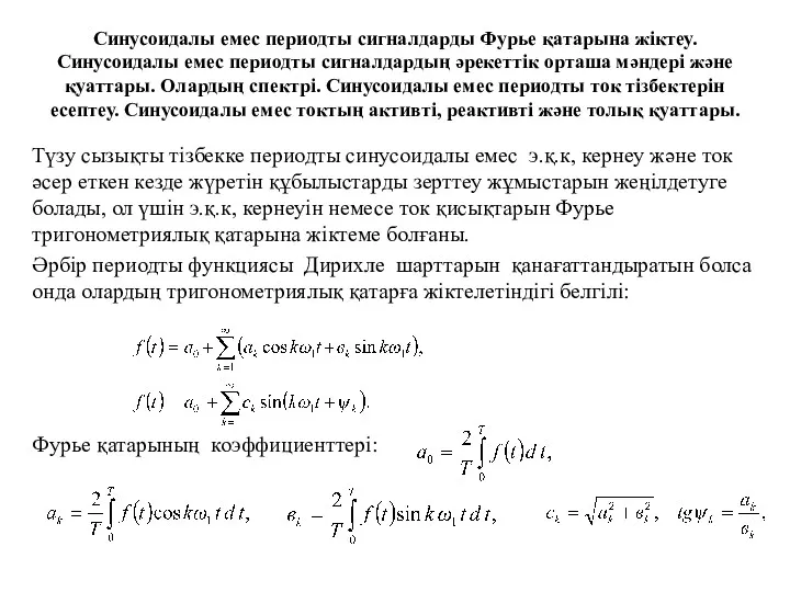 Синусоидалы емес периодты сигналдарды Фурье қатарына жіктеу. Синусоидалы емес периодты сигналдардың әрекеттік орташа мәндері
 Система живлення двигуна УТД-20С1 повітрям
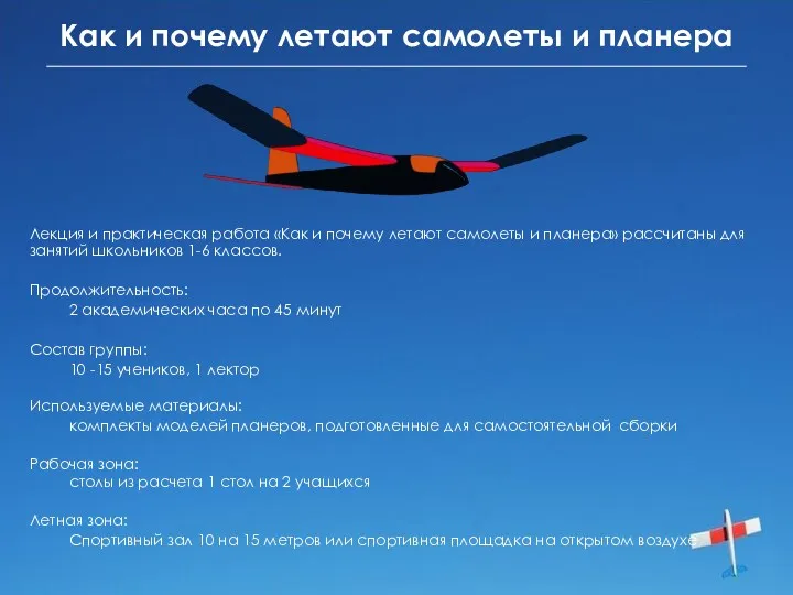 Как и почему летают самолеты и планера
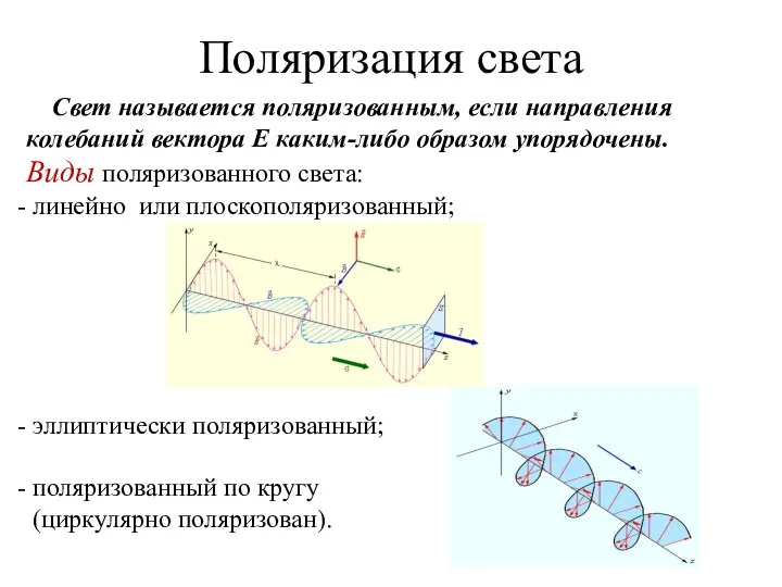 Поляризация света
 Ядерная физика. (Урок-обобщение). 9 класс
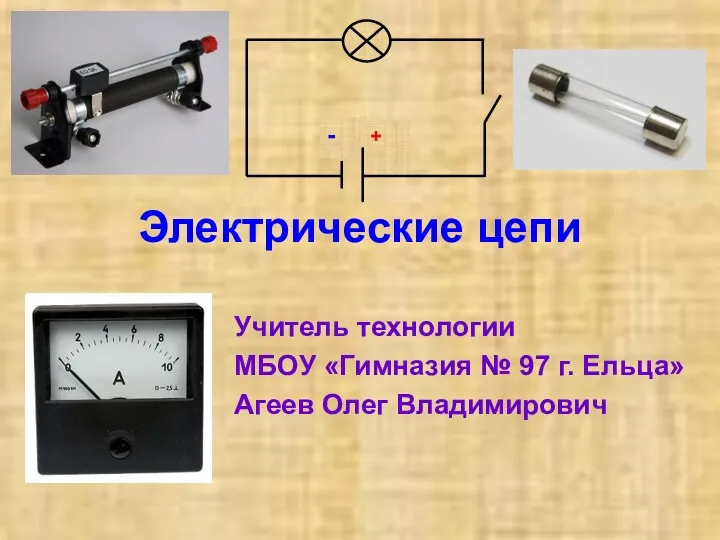 Электрические цепи
 Принцип действия тепловых двигателей
 Физика и техника
 Качественные задачи по физике
 Повышение качества образования по предмету физика через систему использования интегрированных уроков в условиях модернизации образовательной системы РФ
 Рентгеновские аппараты. Цифровые рентгенодиагностические комплексы. (Лекция 10)
 Первый закон термодинамики
 Сила упругости
 Основы триботехники. Лекция 1
 Лекция 8.2. Диэлектрические материалы. Классификация
 Анализ технико-экономической эффективности КПГУ на базе паротурбинной установки ПТ-135/165-130/15