- Radiographic testing

Содержание
- 2. Content Introduction Theory and principles Radiographic equipment and accessories Variables Techniques and procedures Radiographic evaluation Applications
- 3. Introduction This presentation shows information about the NDT method of radiographic inspection or radiography. Radiography uses
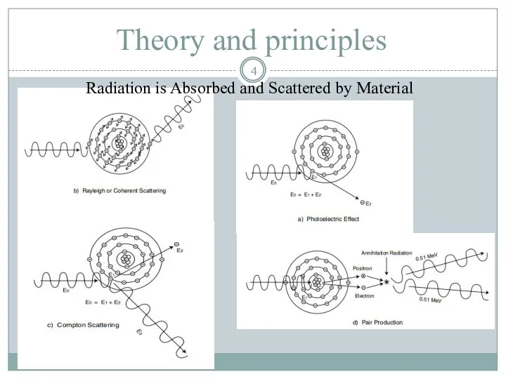
- 4. Theory and principles Radiation is Absorbed and Scattered by Material
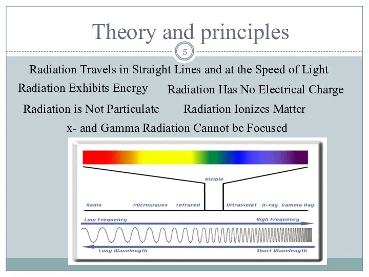
- 5. Theory and principles Radiation Travels in Straight Lines and at the Speed of Light Radiation Exhibits
- 6. General Principles of Radiography Top view of developed film X-ray film The film darkness (density) will
- 7. General Principles of Radiography The energy of the radiation affects its penetrating power. Higher energy radiation
- 8. Gamma Radiography Gamma rays are produced by a radioisotope. A radioisotope has an unstable nuclei that
- 9. Gamma Radiography Unlike X-rays, which are produced by a machine, gamma rays cannot be turned off.
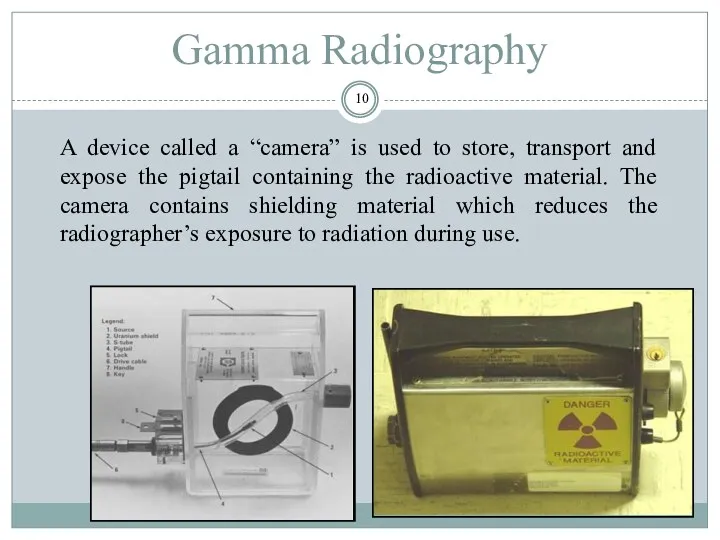
- 10. Gamma Radiography A device called a “camera” is used to store, transport and expose the pigtail
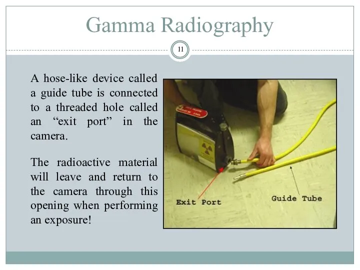
- 11. Gamma Radiography A hose-like device called a guide tube is connected to a threaded hole called
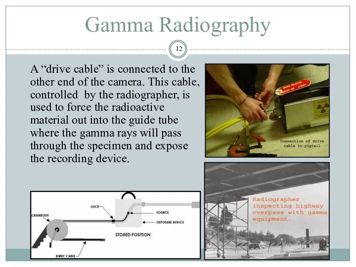
- 12. Gamma Radiography A “drive cable” is connected to the other end of the camera. This cable,
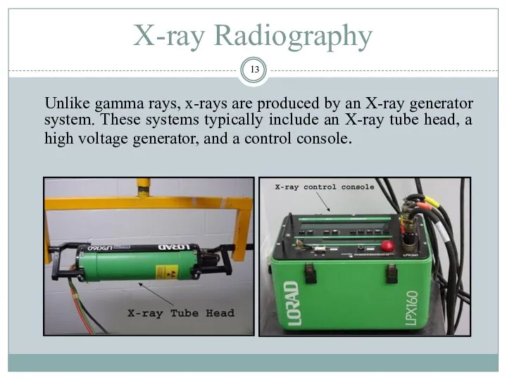
- 13. X-ray Radiography Unlike gamma rays, x-rays are produced by an X-ray generator system. These systems typically
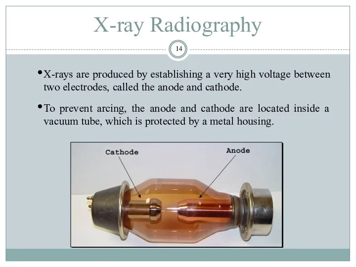
- 14. X-ray Radiography X-rays are produced by establishing a very high voltage between two electrodes, called the
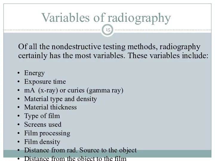
- 15. Variables of radiography Of all the nondestructive testing methods, radiography certainly has the most variables. These
- 16. Variables of radiography In order to control these variables so that the benefits can be maximized
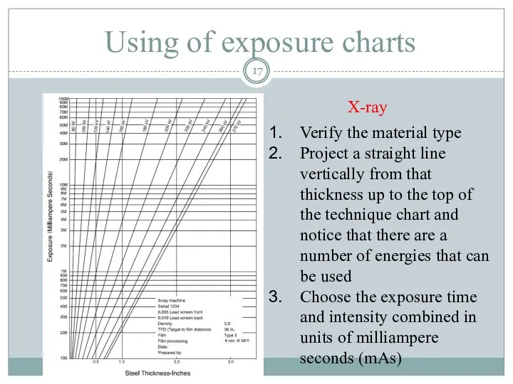
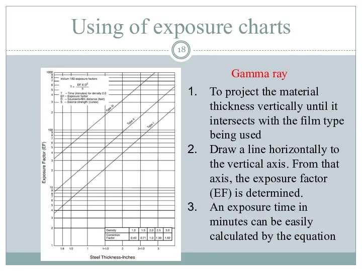
- 17. Using of exposure charts Verify the material type Project a straight line vertically from that thickness
- 18. Using of exposure charts To project the material thickness vertically until it intersects with the film
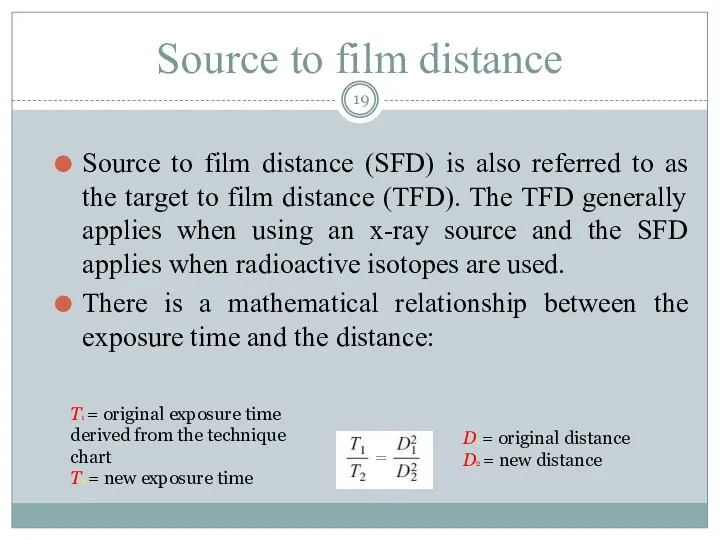
- 19. Source to film distance Source to film distance (SFD) is also referred to as the target
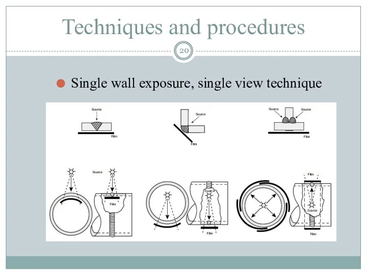
- 20. Techniques and procedures Single wall exposure, single view technique
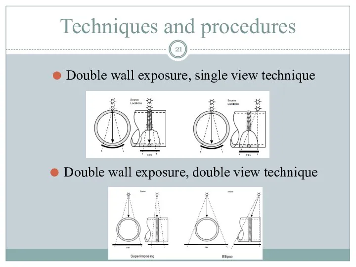
- 21. Techniques and procedures Double wall exposure, single view technique Double wall exposure, double view technique
- 22. Procedure Understand the codes, specifications, and customer requirements thoroughly Develop a technique based on the thickness
- 23. Radiographic Film Class I is described as extra-fine grain, low speed, with very high contrast capabilities.
- 24. Film processing Developing Developers are alkaline solutions that change the latent or chemically stored image in
- 25. Density of the film Film density is defined as the quantitative measure of film blackening as
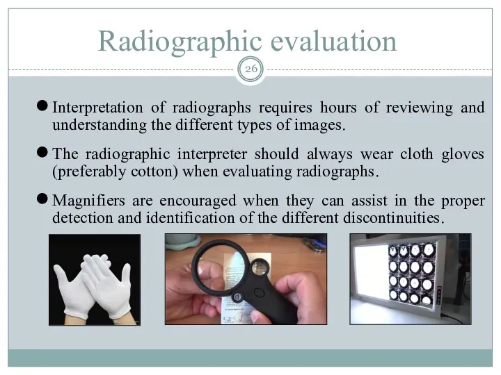
- 26. Radiographic evaluation Interpretation of radiographs requires hours of reviewing and understanding the different types of images.
- 27. Image Quality Image quality is critical for accurate assessment of a test specimen’s integrity. Various tools
- 28. Image Quality IQIs are typically placed on or next to a test specimen. Quality typically being
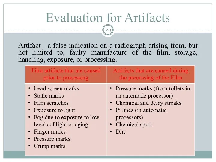
- 29. Evaluation for Artifacts Artifact - a false indication on a radiograph arising from, but not limited
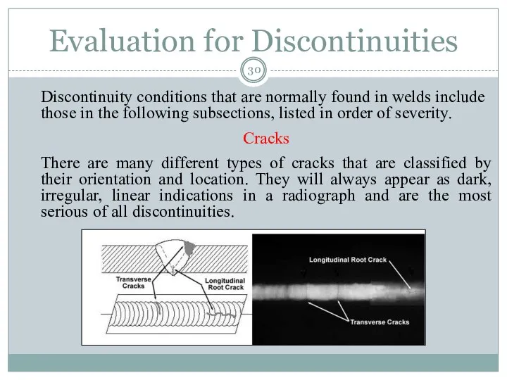
- 30. Evaluation for Discontinuities Discontinuity conditions that are normally found in welds include those in the following
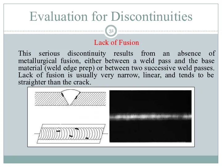
- 31. Evaluation for Discontinuities Lack of Fusion This serious discontinuity results from an absence of metallurgical fusion,
- 32. Incomplete Penetration This discontinuity is an absence of weld metal or an area of “nonfusion” in
- 33. Inclusions (Dense and Less Dense) Inclusions are basically materials that have been entrapped in the weld
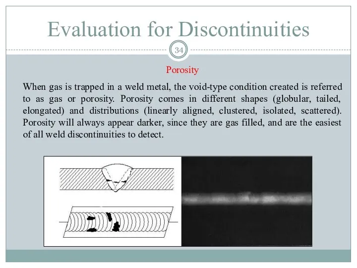
- 34. Porosity When gas is trapped in a weld metal, the void-type condition created is referred to
- 35. There are also geometric conditions that can occur in welds that are observable in a radiograph
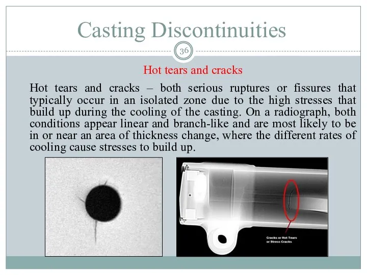
- 36. Casting Discontinuities Hot tears and cracks Hot tears and cracks – both serious ruptures or fissures
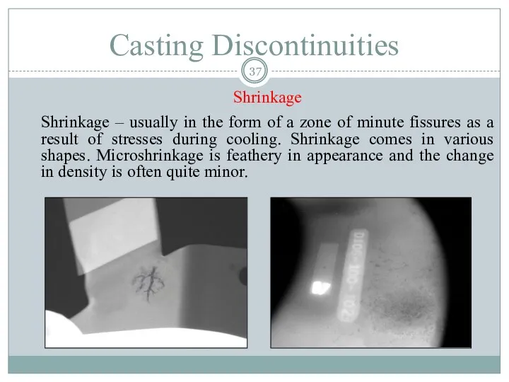
- 37. Casting Discontinuities Shrinkage Shrinkage – usually in the form of a zone of minute fissures as
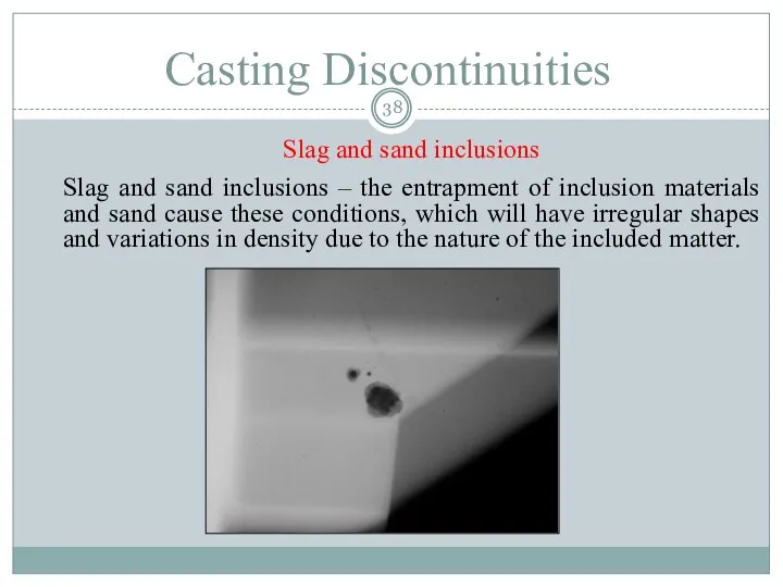
- 38. Casting Discontinuities Slag and sand inclusions Slag and sand inclusions – the entrapment of inclusion materials
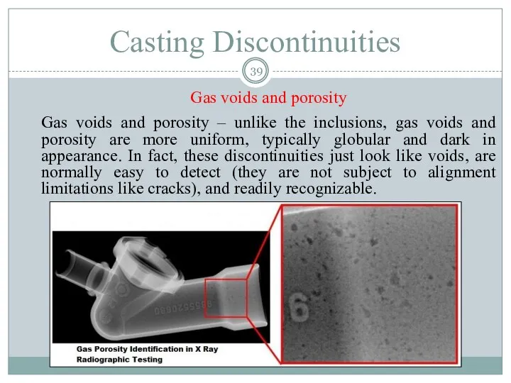
- 39. Casting Discontinuities Gas voids and porosity Gas voids and porosity – unlike the inclusions, gas voids
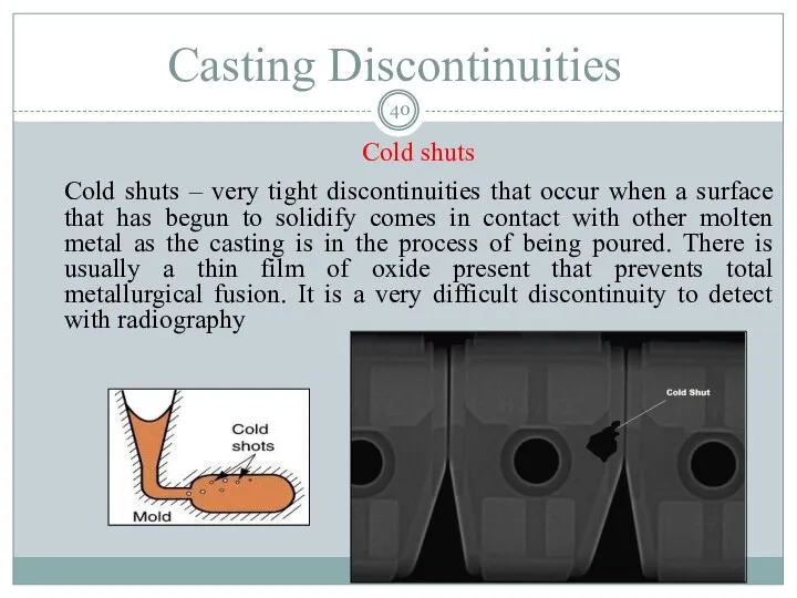
- 40. Casting Discontinuities Cold shuts Cold shuts – very tight discontinuities that occur when a surface that
- 41. There are also geometric conditions in castings that can be observed radiographically. These geometric conditions include
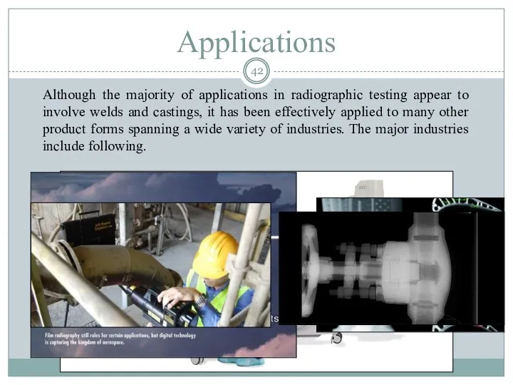
- 42. Applications Although the majority of applications in radiographic testing appear to involve welds and castings, it
- 43. Advantages of Radiography Provides an extremely accurate and permanent record Is very versatile and can be
- 44. Limitations 1. There are safety hazards with the use of radiation devices 2. RT has thickness
- 46. Скачать презентацию
Content
Introduction
Theory and principles
Radiographic equipment and accessories
Variables
Techniques and procedures
Radiographic evaluation
Applications
Advantages and limitations
Content
Introduction
Theory and principles
Radiographic equipment and accessories
Variables
Techniques and procedures
Radiographic evaluation
Applications
Advantages and limitations
Introduction
This presentation shows information about the NDT method of radiographic inspection
Introduction
This presentation shows information about the NDT method of radiographic inspection
Theory and principles
Radiation is Absorbed and Scattered by Material
Theory and principles
Radiation is Absorbed and Scattered by Material
Theory and principles
Radiation Travels in Straight Lines and at the Speed
Theory and principles
Radiation Travels in Straight Lines and at the Speed
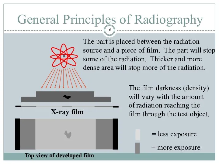
General Principles of Radiography
Top view of developed film
X-ray film
The film
General Principles of Radiography
Top view of developed film
X-ray film
The film
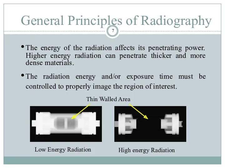
General Principles of Radiography
The energy of the radiation affects its penetrating
General Principles of Radiography
The energy of the radiation affects its penetrating
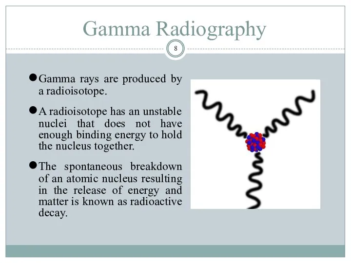
Gamma Radiography
Gamma rays are produced by a radioisotope.
A radioisotope has
Gamma Radiography
Gamma rays are produced by a radioisotope.
A radioisotope has
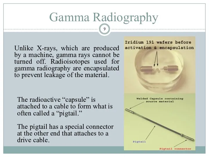
Gamma Radiography
Unlike X-rays, which are produced by a machine, gamma rays
Gamma Radiography
Unlike X-rays, which are produced by a machine, gamma rays
Gamma Radiography
A device called a “camera” is used to store, transport
Gamma Radiography
A device called a “camera” is used to store, transport
Gamma Radiography
A hose-like device called a guide tube is connected to
Gamma Radiography
A hose-like device called a guide tube is connected to
Gamma Radiography
A “drive cable” is connected to the other end of
Gamma Radiography
A “drive cable” is connected to the other end of
X-ray Radiography
Unlike gamma rays, x-rays are produced by an X-ray generator
X-ray Radiography
Unlike gamma rays, x-rays are produced by an X-ray generator
X-ray Radiography
X-rays are produced by establishing a very high voltage between
X-ray Radiography
X-rays are produced by establishing a very high voltage between
Variables of radiography
Of all the nondestructive testing methods, radiography certainly has
Variables of radiography
Of all the nondestructive testing methods, radiography certainly has
Variables of radiography
In order to control these variables so that the
Variables of radiography
In order to control these variables so that the
Using of exposure charts
Verify the material type
Project a straight line vertically
Using of exposure charts
Verify the material type
Project a straight line vertically
Using of exposure charts
To project the material thickness vertically until it
Using of exposure charts
To project the material thickness vertically until it
Source to film distance
Source to film distance (SFD) is also referred
Source to film distance
Source to film distance (SFD) is also referred
Techniques and procedures
Single wall exposure, single view technique
Techniques and procedures
Single wall exposure, single view technique
Techniques and procedures
Double wall exposure, single view technique
Double wall exposure, double
Techniques and procedures
Double wall exposure, single view technique
Double wall exposure, double
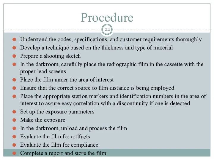
Procedure
Understand the codes, specifications, and customer requirements thoroughly
Develop a technique
Procedure
Understand the codes, specifications, and customer requirements thoroughly
Develop a technique
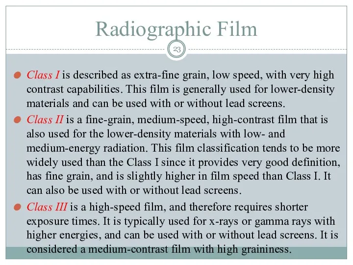
Radiographic Film
Class I is described as extra-fine grain, low speed, with
Radiographic Film
Class I is described as extra-fine grain, low speed, with
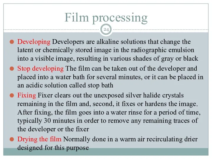
Film processing
Developing Developers are alkaline solutions that change the latent or
Film processing
Developing Developers are alkaline solutions that change the latent or
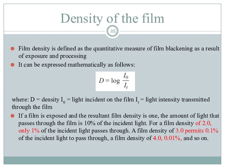
Density of the film
Film density is defined as the quantitative measure
Density of the film
Film density is defined as the quantitative measure
Radiographic evaluation
Interpretation of radiographs requires hours of reviewing and understanding the
Radiographic evaluation
Interpretation of radiographs requires hours of reviewing and understanding the
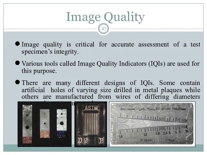
Image Quality
Image quality is critical for accurate assessment of a test
Image Quality
Image quality is critical for accurate assessment of a test
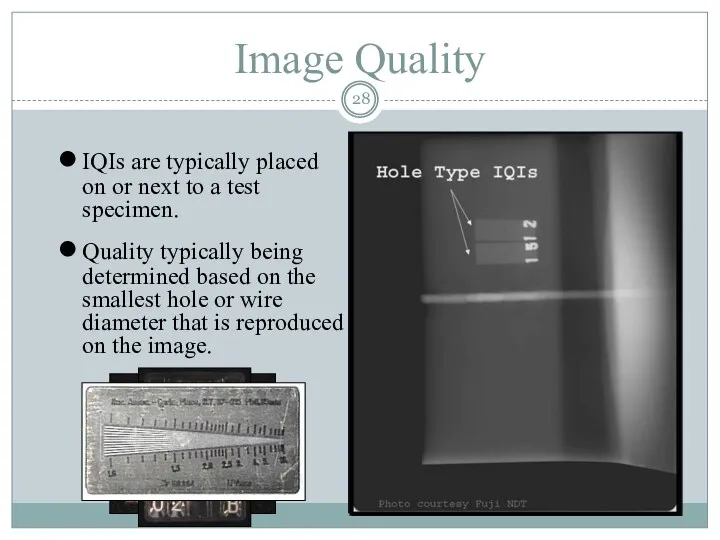
Image Quality
IQIs are typically placed on or next to a test
Image Quality
IQIs are typically placed on or next to a test
Evaluation for Artifacts
Artifact - a false indication on a radiograph arising
Evaluation for Artifacts
Artifact - a false indication on a radiograph arising
Evaluation for Discontinuities
Discontinuity conditions that are normally found in welds include
Evaluation for Discontinuities
Discontinuity conditions that are normally found in welds include
Evaluation for Discontinuities
Lack of Fusion
This serious discontinuity results from an absence
Evaluation for Discontinuities
Lack of Fusion
This serious discontinuity results from an absence
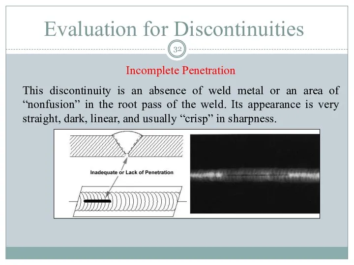
Incomplete Penetration
This discontinuity is an absence of weld metal or an
Incomplete Penetration
This discontinuity is an absence of weld metal or an
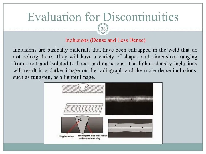
Inclusions (Dense and Less Dense)
Inclusions are basically materials that have been
Inclusions (Dense and Less Dense)
Inclusions are basically materials that have been
Porosity
When gas is trapped in a weld metal, the void-type condition
Porosity
When gas is trapped in a weld metal, the void-type condition
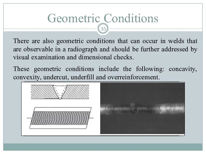
There are also geometric conditions that can occur in welds that
There are also geometric conditions that can occur in welds that
Casting Discontinuities
Hot tears and cracks
Hot tears and cracks – both serious
Casting Discontinuities
Hot tears and cracks
Hot tears and cracks – both serious
Casting Discontinuities
Shrinkage
Shrinkage – usually in the form of a zone of
Casting Discontinuities
Shrinkage
Shrinkage – usually in the form of a zone of
Casting Discontinuities
Slag and sand inclusions
Slag and sand inclusions – the entrapment
Casting Discontinuities
Slag and sand inclusions
Slag and sand inclusions – the entrapment
Casting Discontinuities
Gas voids and porosity
Gas voids and porosity – unlike the
Casting Discontinuities
Gas voids and porosity
Gas voids and porosity – unlike the
Casting Discontinuities
Cold shuts
Cold shuts – very tight discontinuities that occur when
Casting Discontinuities
Cold shuts
Cold shuts – very tight discontinuities that occur when
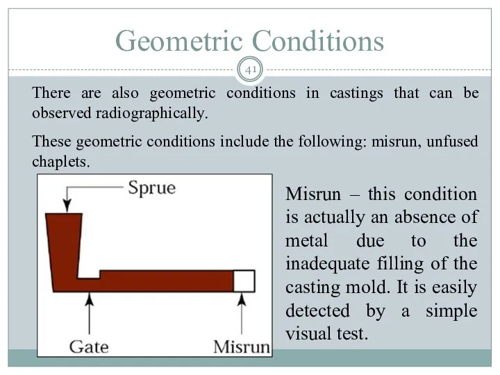
There are also geometric conditions in castings that can be observed
There are also geometric conditions in castings that can be observed
Applications
Although the majority of applications in radiographic testing appear to involve
Applications
Although the majority of applications in radiographic testing appear to involve
Advantages of Radiography
Provides an extremely accurate and permanent record
Is very versatile
Advantages of Radiography
Provides an extremely accurate and permanent record
Is very versatile
Limitations
1. There are safety hazards with the use of radiation devices
2.
Limitations
1. There are safety hazards with the use of radiation devices
2.
 Тепловой насос. Принцип его действия
 Міцність при змінних навантаженнях. (Лекція 4)
 Презентация Механическое движение
 Laws of Thermodynamics
 Щелевые антенны. (Лекция 11)
 Дополнительный материал по физике для 7 класса - 1 и 2 часть
 Основи термодинаміки. Підготовка до контрольної роботи
 Проводник в электроститческом поле. Электроемксоть. Энергия
 Скорость света
 Электрический ток в газах
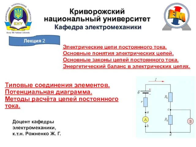 Электрические цепи постоянного тока
 Закон Ома
 Оптика. Поляризация света (лекция 25)
 Закон Кулона. Электрическое поле. Напряженность электрического поля. Принцип суперпозиции полей. Силовые линии электрического
 Путь к звездам
 Электрический ток в газах. Газовый разряд. 10 класс
 Сопла и диффузоры. Истечение жидкостей, паров и газов
 Кинематика, обобщение темы
 Влияние звука на живые организмы
 Конспект урока по физике в 8 классе по теме Линзы. Оптичесая сила линзы
 Свободное паление тел. Движение с постоянным ускорением свободного падения
 Магнит өрісі
 Электрическая лампа
 Презентация по физике Механические колебания
 Дифракция света. Дифракция Френеля и Фраунгофера
 Дисперсия. Дифракция. Интерференция. Физический диктант
 Почему радуга разноцветная
 Электронное управление трансмиссией автомобиля. Система активного распределения крутящего момента. Урок 190