- Compass-3d

Содержание
- 2. COMPASS is a product of the Russian company "ASKON".This is a computer-aided design system with the
- 3. This CAD comes in several versions: Compass-3D, Compass CHART, Compass-SPDS, Compass-3D LTCompass-3D Home That are designed
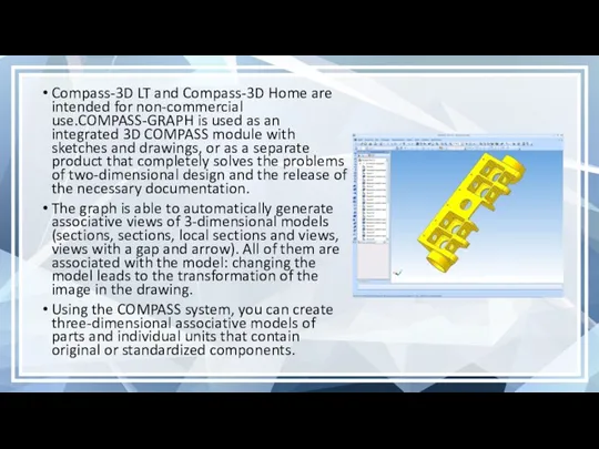
- 4. Compass-3D LT and Compass-3D Home are intended for non-commercial use.COMPASS-GRAPH is used as an integrated 3D
- 5. In the COMPASS CAD, various calculations and analysis of products are performed by the following modules:
- 6. Program Features Own core. The program is built on its own, unique core that supports the
- 7. Commercial versions Compass-3DThe Compass-3D system is designed to create three-dimensional associative models of individual parts and
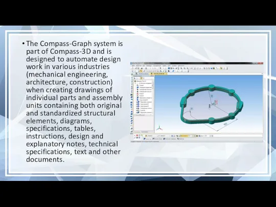
- 8. The Compass-Graph system is part of Compass-3D and is designed to automate design work in various
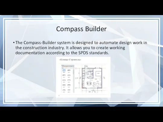
- 9. Compass Builder The Compass-Builder system is designed to automate design work in the construction industry. It
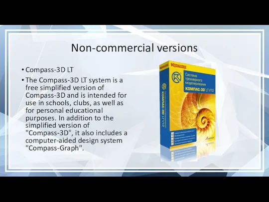
- 10. Non-commercial versions Compass-3D LT The Compass-3D LT system is a free simplified version of Compass-3D and
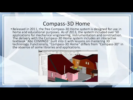
- 11. Compass-3D Home Released in 2011, the free Compass-3D Home system is designed for use in home
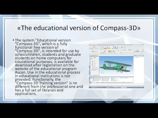
- 12. «The educational version of Compass-3D» The system "Educational version "Compass-3D", which is a fully functional free
- 13. The compass program and its features COMPASS is a 3D multi-window and multi-document system. Windows of
- 14. A part is a model of a product made of a homogeneous material, without the use
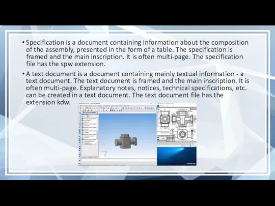
- 15. Specification is a document containing information about the composition of the assembly, presented in the form
- 16. Familiarization with the system interface An interface is a shell of a software product that carries
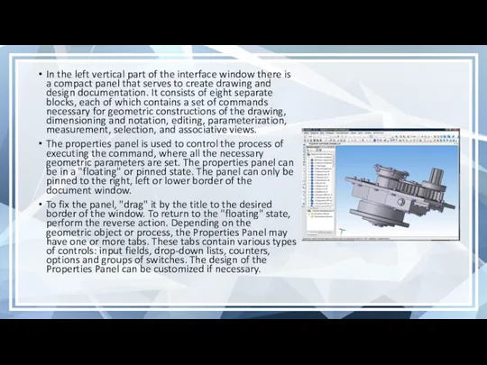
- 17. In the left vertical part of the interface window there is a compact panel that serves
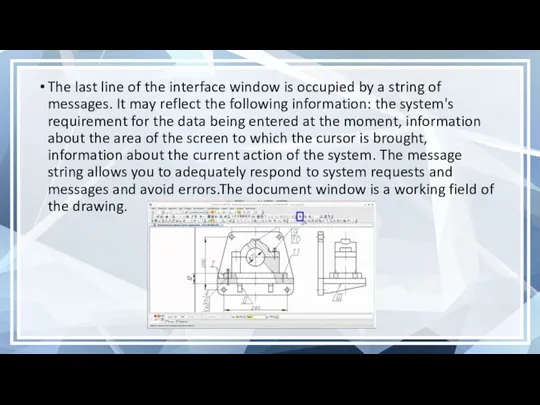
- 18. The last line of the interface window is occupied by a string of messages. It may
- 19. File. Activation of the menu bar is achieved by clicking on the image of the command
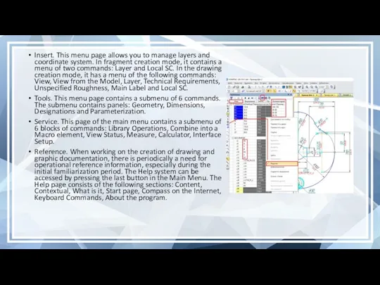
- 20. Insert. This menu page allows you to manage layers and coordinate system. In fragment creation mode,
- 22. Скачать презентацию
COMPASS is a product of the Russian company "ASKON".This is a computer-aided design
COMPASS is a product of the Russian company "ASKON".This is a computer-aided design
This CAD comes in several versions:
Compass-3D,
Compass CHART,
Compass-SPDS,
Compass-3D LTCompass-3D Home
That are designed for three-dimensional
This CAD comes in several versions:
Compass-3D,
Compass CHART,
Compass-SPDS,
Compass-3D LTCompass-3D Home
That are designed for three-dimensional
Compass-3D LT and Compass-3D Home are intended for non-commercial use.COMPASS-GRAPH is used as
Compass-3D LT and Compass-3D Home are intended for non-commercial use.COMPASS-GRAPH is used as
In the COMPASS CAD, various calculations and analysis of products are performed by
In the COMPASS CAD, various calculations and analysis of products are performed by
Program Features
Own core. The program is built on its own, unique core that
Program Features
Own core. The program is built on its own, unique core that
Commercial versions
Compass-3DThe Compass-3D system is designed to create three-dimensional associative models of individual
Commercial versions
Compass-3DThe Compass-3D system is designed to create three-dimensional associative models of individual
The Compass-Graph system is part of Compass-3D and is designed to automate design
The Compass-Graph system is part of Compass-3D and is designed to automate design
Compass Builder
The Compass-Builder system is designed to automate design work in the
Compass Builder
The Compass-Builder system is designed to automate design work in the
Non-commercial versions
Compass-3D LT
The Compass-3D LT system is a free simplified version of Compass-3D
Non-commercial versions
Compass-3D LT
The Compass-3D LT system is a free simplified version of Compass-3D
Compass-3D Home
Released in 2011, the free Compass-3D Home system is designed for
Compass-3D Home
Released in 2011, the free Compass-3D Home system is designed for
«The educational version of Compass-3D»
The system "Educational version "Compass-3D", which is a
«The educational version of Compass-3D»
The system "Educational version "Compass-3D", which is a
The compass program and its features
COMPASS is a 3D multi-window and multi-document system.
The compass program and its features
COMPASS is a 3D multi-window and multi-document system.
A part is a model of a product made of a homogeneous material,
A part is a model of a product made of a homogeneous material,
Specification is a document containing information about the composition of the assembly, presented
Specification is a document containing information about the composition of the assembly, presented
Familiarization with the system interface
An interface is a shell of a software product
Familiarization with the system interface
An interface is a shell of a software product
In the left vertical part of the interface window there is a compact
In the left vertical part of the interface window there is a compact
The last line of the interface window is occupied by a string of
The last line of the interface window is occupied by a string of
File. Activation of the menu bar is achieved by clicking on the image
File. Activation of the menu bar is achieved by clicking on the image
Insert. This menu page allows you to manage layers and coordinate system. In
Insert. This menu page allows you to manage layers and coordinate system. In
 Blender (часть 1)
 Понятие алгоритма
 Классификация программных продуктов
 Цифровая связь. IP телефония. Технология Scype
 Профессия по специальности “Компьютерные сети”
 Разработка Telegram - бота для доставки воды
 Знакомство с компонентами
 Информационное обеспечение ИС. Комплекс средств проектирования
 Локальные компьютерные сети
 Млечный путь-2
 Олимпиадные задания по ИТ.
 Есептеу құрылғыларының даму тарихы
 Lab works 1-4
 Текстовые документы и технологии их создания
 Традиционный подход сбора, хранения и обработки данных
 Поняття користувача й сеансу користувача. Урок 27
 Автоматы и формальные языки
 Рекомендации по созданию презентаций Microsoft PowerPoint
 Microsoft® Office Excel® 2007. Что изменилось и почему?
 Мануал для новичков
 Методическая разработка внеклассного мероприятия Турнир знатоков Информатики Внеклассное мероприятие по информатике для учащихся 6-го класса Внеклассное мероприятие по информатике для учащихся 6-го класса Турнир знатоков ИНФОРМАТ
 Microsoft Excel. Основные понятия
 -1763094957
 Кәсіптік білім берудегі оқытудың интерактивті технологиялары
 Лабораторные работы
 Обзор программных средств для создания WEB-сайтов
 Добро пожаловать в PowerPoint! 5 советов, которые помогут вам упростить работу
 Операторы. Лекция 3