- Conceptual design. Database Management Systems. Lecture 2

Содержание
- 2. Database Design Stages Subject Area Analysis Conceptual Design Logical Design Physical Design
- 3. Conceptual Modeling ER model (entity-relationship model) is a way of graphically representing the logical relationships of
- 4. To design an ER model you should know … Entities Attributes Relationships
- 5. First notation - Chen’s notation Entities (rectangle shape) Attributes (oval shape) Relationship (rhombus shape)
- 6. Example Entities: Students Teachers Subjects Attributes Students (stud_id, name, email, group) Teachers (teach_id, name, email, department)
- 7. ER-diagram with Chen’s notation
- 8. Different types of Notations Chen’s Notation Bachman notation IDEF1X Martin notation (Crow’s foot) min, max-notation UML
- 9. Different types of Notations Various methods of representing the same one to many relationship. In each
- 10. Relationships Types: One–to-One One-to-Many Many-to-Many Rows in a table can be linked to rows in other
- 11. One-to-one One instance of an entity (A) is associated with one other instance of another entity
- 12. Example of one-to-one
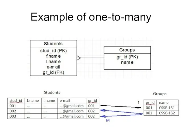
- 13. One-to-many One instance of an entity (A) is associated with one or many instances of another
- 14. Example of one-to-many
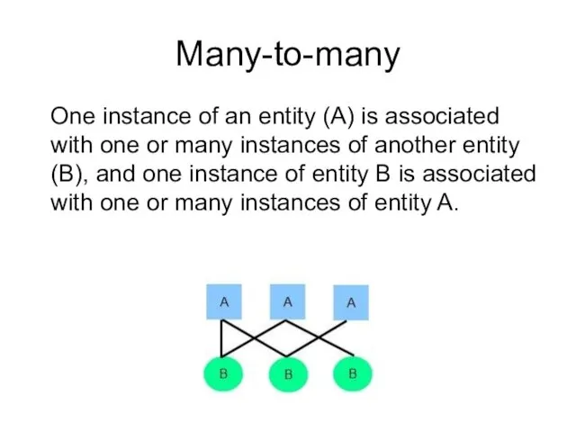
- 15. Many-to-many One instance of an entity (A) is associated with one or many instances of another
- 16. Example of many-to-many 21
- 17. Example of many-to-many 22
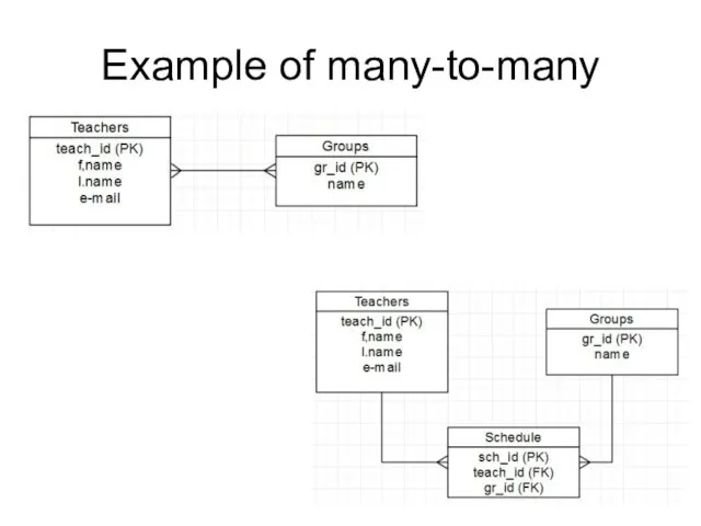
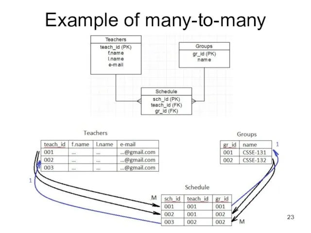
- 18. Example of many-to-many 23
- 19. Tools Gliffy.com Сreately.com Draw.io MS Visio Erwin etc.
- 21. Скачать презентацию
Database Design
Stages
Subject Area Analysis
Conceptual Design
Logical Design
Physical Design
Database Design
Stages
Subject Area Analysis
Conceptual Design
Logical Design
Physical Design
Conceptual Modeling
ER model (entity-relationship model) is a way of graphically representing
Conceptual Modeling
ER model (entity-relationship model) is a way of graphically representing
To design an ER model you should know …
Entities
Attributes
Relationships
To design an ER model you should know …
Entities
Attributes
Relationships
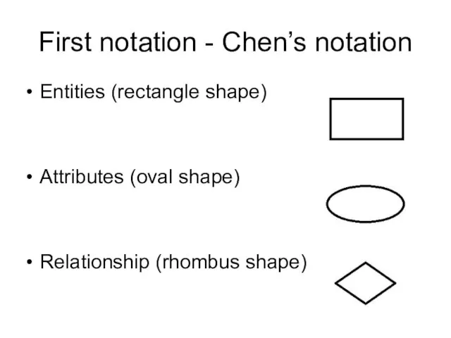
First notation - Chen’s notation
Entities (rectangle shape)
Attributes (oval shape)
Relationship (rhombus shape)
First notation - Chen’s notation
Entities (rectangle shape)
Attributes (oval shape)
Relationship (rhombus shape)
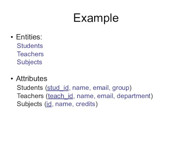
Example
Entities:
Students
Teachers
Subjects
Attributes
Students (stud_id, name, email, group)
Teachers (teach_id, name, email, department)
Subjects (id, name,
Example
Entities:
Students
Teachers
Subjects
Attributes
Students (stud_id, name, email, group)
Teachers (teach_id, name, email, department)
Subjects (id, name,
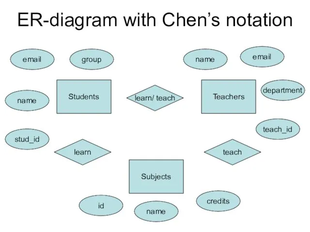
ER-diagram with Chen’s notation
ER-diagram with Chen’s notation
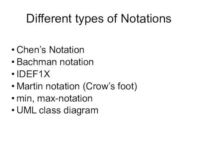
Different types of Notations
Chen’s Notation
Bachman notation
IDEF1X
Martin notation (Crow’s foot)
min, max-notation
UML class
Different types of Notations
Chen’s Notation
Bachman notation
IDEF1X
Martin notation (Crow’s foot)
min, max-notation
UML class
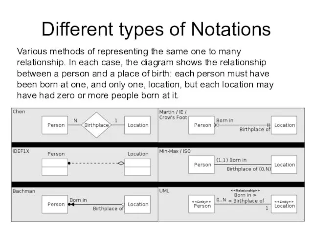
Different types of Notations
Various methods of representing the same one to
Different types of Notations
Various methods of representing the same one to
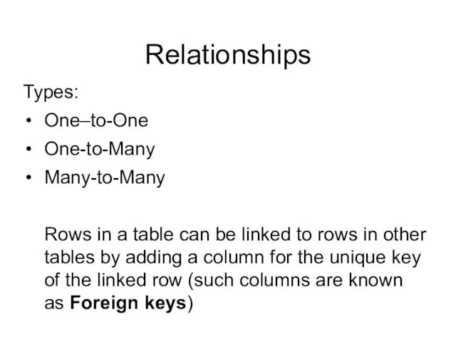
Relationships
Types:
One–to-One
One-to-Many
Many-to-Many
Rows in a table can be linked to rows in other
Relationships
Types:
One–to-One
One-to-Many
Many-to-Many
Rows in a table can be linked to rows in other
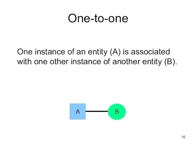
One-to-one
One instance of an entity (A) is associated with one other
One-to-one
One instance of an entity (A) is associated with one other
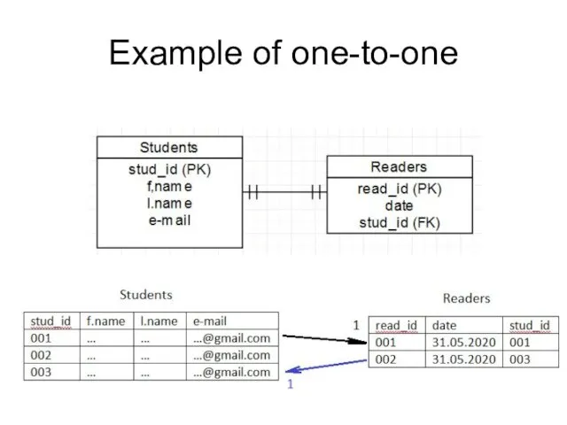
Example of one-to-one
Example of one-to-one
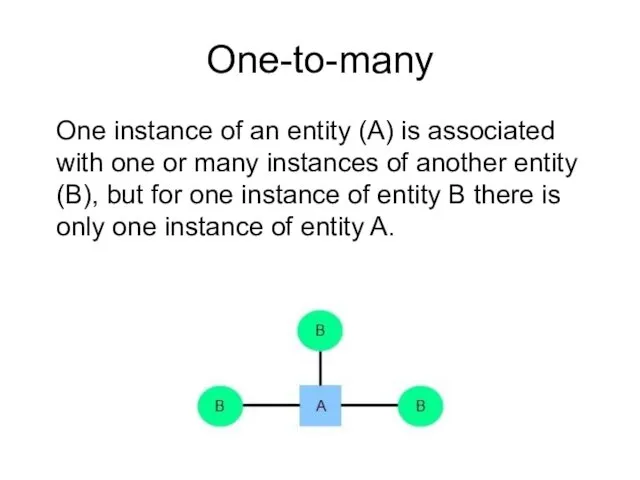
One-to-many
One instance of an entity (A) is associated with one or
One-to-many
One instance of an entity (A) is associated with one or
Example of one-to-many
Example of one-to-many
Many-to-many
One instance of an entity (A) is associated with one or
Many-to-many
One instance of an entity (A) is associated with one or
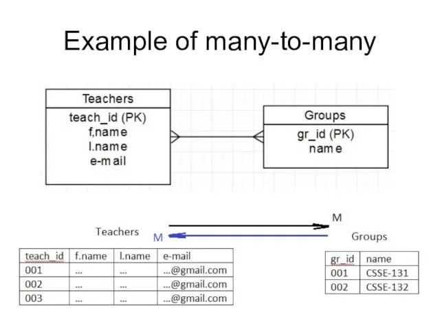
Example of many-to-many
21
Example of many-to-many
21
Example of many-to-many
22
Example of many-to-many
22
Example of many-to-many
23
Example of many-to-many
23
Tools
Gliffy.com
Сreately.com
Draw.io
MS Visio
Erwin
etc.
Tools
Gliffy.com
Сreately.com
Draw.io
MS Visio
Erwin
etc.
 Багатовимірні масиви
 Информационные жанры
 Функциональные зависимости в реляционной модели данных. Декомпозиция. Нормальные формы
 Научный корреспондент. Открытая публикация учебных и научных работ
 Анализ документов
 Практическое занятие Построение графиков функций в Excel
 Алгоритмическая конструкция
 Блог: легко и просто. Часть 1: LiveJournal
 Java Introduction Object Oriented Programming
 Создание сайтов
 Программирование на языке Python (часть 2)
 Безопасный интернет
 Двомірні масиви. Типові операції з масивами
 კომპიუტერის აპარატურული უზრუნველყოფა
 SCM515 Контроль счетов
 Выпускная квалификационная работа. Тема Организация безопасности беспроводной сети стандарта WI-FI
 Переменные. Модуль 1. Урок 2. Международная школа программирования для детей
 Графические операторы языка Qbasic
 Принципы построения распределенных баз данных
 Представление данных в ЭВМ
 Табличный процессор Excel. Часть 1
 Записи в языке Pascal
 Модель OSI. Сети доступа. Лекция 3
 Локальные и глобальные сети ЭВМ
 Кодирование информации
 Презентация к методической разработке
 Normalisation. Describe relational databases and their use
 Паттерны параллельного проектирования приложений, выполнение части программ на GPU. Лекция 3.3