Слайд 2
Overview
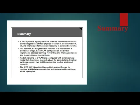
A VLAN is a group of end stations with a common
set of requirements, independent of their physical location.
A VLAN has the same attributes as a physical LAN, but allows you to group end stations even if they are not physically located on the same LAN segment.
A VLAN allows you to group ports on a switch to limit unicast, multicast, and broadcast traffic flooding.
Flooded traffic that originates from a particular VLAN floods only ports belonging to that VLAN.
You should understand how VLANs operate and the important VLAN protocols in order to configure, verify, and troubleshoot VLANs on Cisco access switches.
This lesson describes VLAN operations and associated protocols.
Слайд 3
Objectives
VLAN operations and protocols. This ability includes being able to meet these
objectives:
Describe the basic features of a VLAN
Explain how Catalyst switches support VLAN functionality
Describe the VLAN membership modes
Explain the functionality provided by 802.1Q trunking
Describe the ISL protocol and encapsulation
Describe the features of VTP
Describe the modes in which VTP operates
Explain how VTP operates in a management domain
Describe how VTP pruning supports VLANs
Слайд 4
VLANs Defined
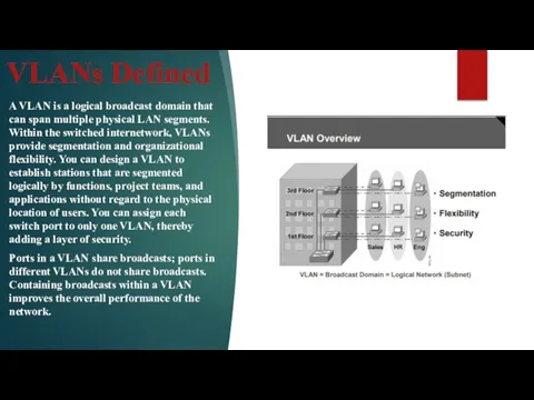
A VLAN is a logical broadcast domain that can span
multiple physical LAN segments. Within the switched internetwork, VLANs provide segmentation and organizational flexibility. You can design a VLAN to establish stations that are segmented logically by functions, project teams, and applications without regard to the physical location of users. You can assign each switch port to only one VLAN, thereby adding a layer of security.
Ports in a VLAN share broadcasts; ports in different VLANs do not share broadcasts. Containing broadcasts within a VLAN improves the overall performance of the network.
Слайд 5
Слайд 6
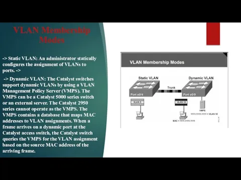
VLAN Membership Modes
-> Static VLAN: An administrator statically configures the assignment
of VLANs to ports. ->
-> Dynamic VLAN: The Catalyst switches support dynamic VLANs by using a VLAN Management Policy Server (VMPS). The VMPS can be a Catalyst 5000 series switch or an external server. The Catalyst 2950 series cannot operate as the VMPS. The VMPS contains a database that maps MAC addresses to VLAN assignments. When a frame arrives on a dynamic port at the Catalyst access switch, the Catalyst switch queries the VMPS for the VLAN assignment based on the source MAC address of the arriving frame.
Слайд 7
802.1Q Trunking
This topic describes the basic functionality provided by 802.1Q trunking.
The
IEEE 802.1Q protocol is used to interconnect multiple switches and routers and define VLAN topologies. Cisco supports IEEE 802.1Q for Fast Ethernet and Gigabit Ethernet interfaces. Trunking is a way to carry traffic from several VLANs over a point-to-point link between the two devices.
You can implement Ethernet trunking in these two ways: Inter-Switch Link ( ISL), a Cisco proprietary protocol 802.1Q, an IEEE standard IEEE 802.1Q extends IP routing capabilities to include support for routing IP frame types in VLAN configurations using the IEEE 802.1Q encapsulation.
Every 802.1Q port is assigned to a trunk. All ports on a trunk are in a native VLAN. Every 802.1Q port is assigned an identifier value that is based on the port’s native VLAN ID (the default is VLAN 1). All untagged frames are assigned to the LAN specified in the ID parameter.
Слайд 8
Example: Per VLAN Spanning Tree +
Cisco developed PVST+ to enable the
running of several STP instances. PVST+ uses a Cisco device to connect an MST zone, typically the 802.1Q-based network of another vendor, to a PVST+ zone, typically a Cisco ISL–based network.
There is no specific configuration needed to achieve this connection. Ideally, a mixed environment should look like the one shown in the figure. PVST+ provides support for 802.1Q trunks and the mapping of multiple spanning trees to the single spanning tree of 802.1Q switches. PVST+ networks must be in a treelike structure for proper STP operation. Providing different STP root switches per VLAN creates a more redundant network.
The PVST+ architecture distinguishes three types of regions: a PVST region, a PVST+ region, and an MST region. Each region consists of a homogeneous switch. You can connect a PVST region to a PVST+ region by connecting two ISL ports. Similarly, you can connect a PVST+ region to an MST region by connecting two 802.1Q ports.
Слайд 9
Inter-Switch Link Protocol and Encapsulation
This topic describes ISL protocol and encapsulation.
ISL
is a Cisco proprietary protocol for interconnecting multiple switches and maintaining VLAN information as traffic travels between switches.
ISL provides VLAN capabilities while maintaining full wire-speed performance over Fast Ethernet links in full- or half-duplex mode. Running a trunk in full-duplex mode is efficient and highly recommended.
ISL operates in a point-to-point environment. The ISL frame tagging that the Catalyst series of switches uses is a low-latency mechanism for multiplexing traffic from multiple VLANs on a single physical path. It has been implemented for connections among switches, routers, and Network Interface Cards (NICs) that are used on nodes such as servers.
Слайд 10
VLAN Trunking Protocol Features
This topic describes the features that VLAN Trunking
Protocol (VTP) offers to support VLANs.
VTP is a Layer 2 messaging protocol that maintains VLAN configuration consistency by managing the additions, deletions, and name changes of VLANs across networks. VTP minimizes misconfigurations and configuration inconsistencies that can cause problems, such as duplicate VLAN names or incorrect VLAN-type specifications. A VTP domain is one switch or several interconnected switches sharing the same VTP environment.
You can configure a switch to be in only one VTP domain. By default, a Catalyst switch is in the no-management-domain state until it receives an advertisement for a domain over a trunk link or until you configure a management domain. Configurations made to a single VTP server are propagated across links to all connected switches in the network.
Слайд 11
VTP Modes
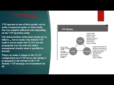
VTP operates in one of three modes: server mode, transparent
mode, or client mode. You can complete different tasks depending on the VTP operation mode.
The characteristics of the three modes are as follows: Server mode: The default VTP mode is server mode, but VLANs are not propagated over the network until a management domain name is specified or learned.
When you make a change to the VLAN configuration on a VTP server, the change is propagated to all switches in the VTP domain. VTP messages are transmitted out all .
Слайд 12
VTP Operations
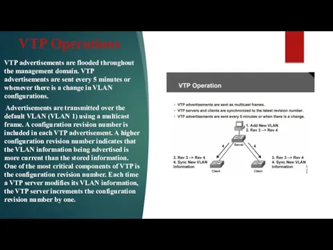
VTP advertisements are flooded throughout the management domain. VTP advertisements are
sent every 5 minutes or whenever there is a change in VLAN configurations.
Advertisements are transmitted over the default VLAN (VLAN 1) using a multicast frame. A configuration revision number is included in each VTP advertisement. A higher configuration revision number indicates that the VLAN information being advertised is more current than the stored information. One of the most critical components of VTP is the configuration revision number. Each time a VTP server modifies its VLAN information, the VTP server increments the configuration revision number by one.
Слайд 13
VTP Pruning and Example: VTP Pruning
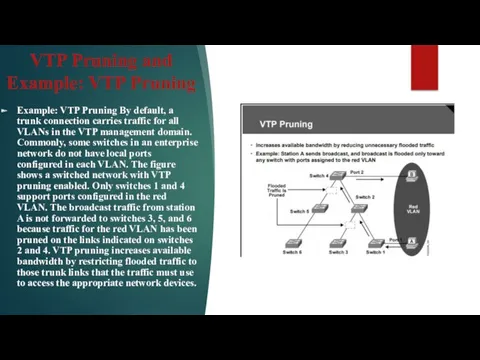
Example: VTP Pruning By default, a
trunk connection carries traffic for all VLANs in the VTP management domain. Commonly, some switches in an enterprise network do not have local ports configured in each VLAN. The figure shows a switched network with VTP pruning enabled. Only switches 1 and 4 support ports configured in the red VLAN. The broadcast traffic from station A is not forwarded to switches 3, 5, and 6 because traffic for the red VLAN has been pruned on the links indicated on switches 2 and 4. VTP pruning increases available bandwidth by restricting flooded traffic to those trunk links that the traffic must use to access the appropriate network devices.
Слайд 14

 Игровая среда программирования Scratch
 Landmin бот
 История вычислительной техники. Викторина
 SMM для start-up
 Устройство компьютера
 Компьютерный турнир (внеклассное мероприятие)
 Представление графов
 Презентация к уроку Системы счисления
 Алгоритм работы с IPTV
 Текстовые процессоры. Лекция 1
 3D принтеры
 Информационная безопасность
 Представление информации, языки, кодирование
 Локальные и глобальные и компьютерные сети
 Системы счисления
 Git. Python tools. Basic operators
 Работа с ПК
 Процессор
 Профилактика вовлечения молодежи Ростовской области в деструктивные организации, в т.ч. через сеть Интернет
 Внеклассное мероприятие Путешествие с Инфознайкой
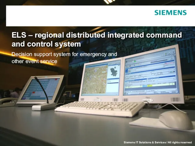 ELS – regional distributed integrated command and control system. Decision support sys
 Особенности электронной почты
 Электронные таблицы Excel
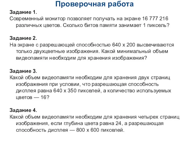 Проверочная работа для 9 класса по теме Кодирование графической информации
 Операционная система Linux
 Технології штучного інтелекту в готельноресторанних комплексах
 Happy start .NET
 Основы журналистики. Пражурналистика и формирование журналистики