- Lin protocol description. Automotive body network

Содержание
- 2. LIN Sub Bus W. Specks, H.-C. Wense Automotive Body Network
- 3. Typical LIN Applications
- 4. MUX Standards (Costs and Speeds) Speed [bit/s] Byteflight optical bus LIN master-slave single wire bus no
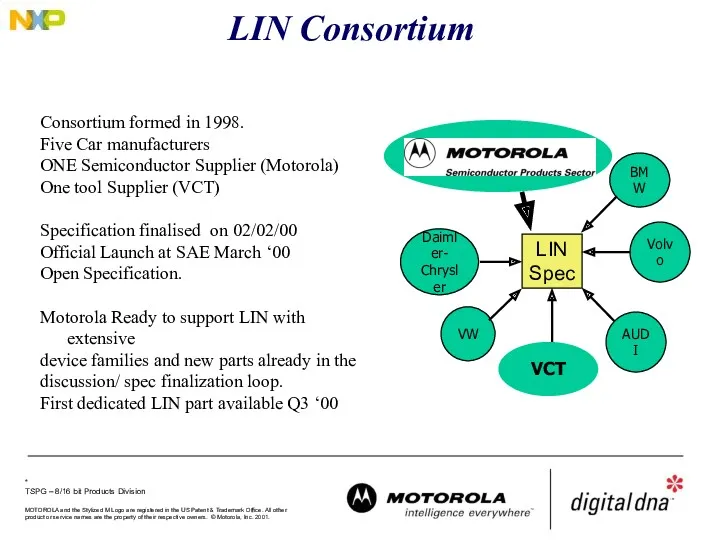
- 5. LIN Consortium Daimler- Chrysler AUDI VW Volvo BMW LIN Spec VCT Consortium formed in 1998. Five
- 6. LIN Standard - Overview Software Level Hardware Level Tools ECU (LIN relevant functions only) Operating System
- 7. Hierarchical Network Structure Flat Network CAN Automotive Standard Bus Compatible with Main Bus Expensive (Die Size/
- 8. Sub-Network: LIN vs. CAN ECU & Gateway CAN SCI Satellite 1 SCI Satellite 2 LIN phys
- 9. SubNets Necessary to reduce Busload on main Bus Solutions CAN Automotive Standard Bus Compatible with Main
- 10. Sub Bus Concept Basic Requirements: Satisfy Need for a Standard for Sub Busses Cost driven: The
- 11. LIN Concept Technical Solution Low cost single-wire implementation (enhanced ISO 9141) Speed up to 20Kbit/s (limited
- 12. Master / Slave Protocol Master Task Determines order and priority of messages. Monitors Data and check
- 13. Master / Slave Protocol Master has control over the whole Bus and Protocol The master controls
- 14. Master/Slave Protocol Slave Is one of 2-16 Members on the Bus and receives or transmits Data
- 15. LIN protocol offers message timing predictability Time Triggered Approach Message Length is known Number of transmitted
- 16. Data Transmission
- 17. Message Frame Synch Byte: Specific Pattern for Determination of Time Base (Determination of the time between
- 18. Identifier The identifier field is sent by the master node to all LIN nodes This identifier
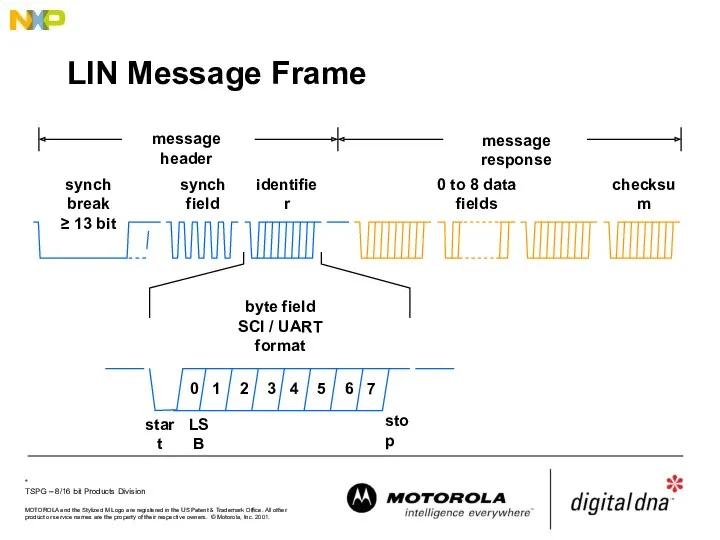
- 19. LIN Message Frame
- 20. LIN Communication - Data from Slave to Master Single-master / multi-slave protocol Time triggered, no arbitration
- 21. LIN Communication - Data from Master to Slave(s)
- 22. LIN Communication - Data from Slave to Slave Slave Node A Slave Task Trans Slave Task
- 23. LIN Message Frame synch break ≥ 13 bit synch field identifier message header Synchronisation frame Synchronisation
- 24. Frame Synchronisation (1) Initial conditions: +/- 4% baud rate accuracy relative the transmitting source A standard
- 25. Frame Synchronisation (2) Initial conditions: +/- 15% baud rate accuracy relative the the LIN master transmitting
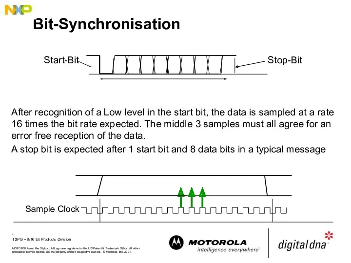
- 26. Bit-Synchronisation A start bit transition to a low logic level (dominant) indicates a start of a
- 27. Bit Sampling
- 28. Bit-Synchronisation After recognition of a Low level in the start bit, the data is sampled at
- 29. Taking account of Ground-Shift The detection point for data transitions can be affected by voltage references.
- 30. LIN Physical Interface VBAT 8...18V GND UART Rx Tx Electronic Control Unit master: 1kΩ slave: 30kΩ
- 31. Examination of whether the Deadline is met response time probability worst-case longest observed response time best-case
- 32. Message latency
- 33. Message latency across a network notional generation new value available for trans-mission new value available for
- 34. Latency optimisation with LIN Window Status Master Command Mirror Status Lock Status Keyboard Status Window Status
- 35. Sub Schedule Table Variables Scheduling Main Schedule Table Sub Schedule Table Sub Schedule Table Alternate Schedule
- 36. Event Triggered Message Problem Specific node communication required but this takes up too much time for
- 37. Further information http://www.lin-subbus.org - Consortium
- 38. LIN Development Flow Database Manager Database LIN Configuration Description File LIN Configuration Tool User provided Information
- 39. LIN Configuration Description File Includes all essential information of network signals, latency periods, cycle times, nodes
- 41. Скачать презентацию
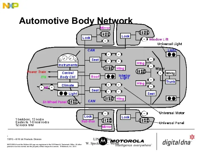
LIN Sub Bus
W. Specks, H.-C. Wense
Automotive Body Network
LIN Sub Bus
W. Specks, H.-C. Wense
Automotive Body Network
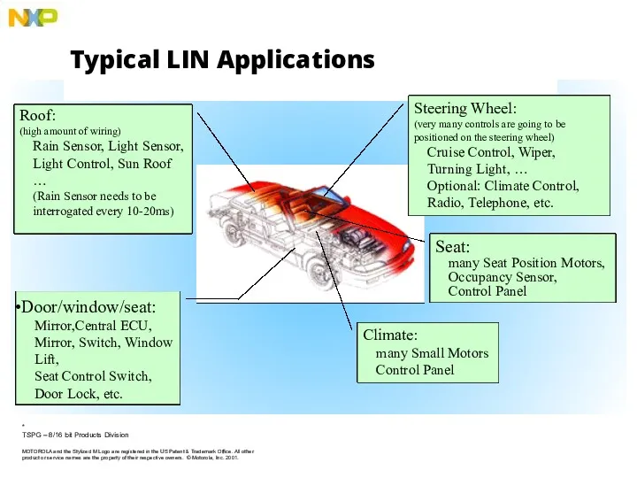
Typical LIN Applications
Typical LIN Applications
![MUX Standards (Costs and Speeds) Speed [bit/s] Byteflight optical bus](/_ipx/f_webp&q_80&fit_contain&s_1440x1080/imagesDir/jpg/205333/slide-3.jpg)
MUX Standards (Costs and Speeds)
Speed [bit/s]
Byteflight
optical bus
LIN
master-slave
single wire bus
no quartz
CAN-B
event triggered
fault
MUX Standards (Costs and Speeds)
Speed [bit/s]
Byteflight
optical bus
LIN
master-slave
single wire bus
no quartz
CAN-B
event triggered
fault
LIN Consortium
Daimler-
Chrysler
AUDI
VW
Volvo
BMW
LIN
Spec
VCT
Consortium formed in 1998.
Five Car manufacturers
ONE Semiconductor Supplier (Motorola)
One tool
LIN Consortium
Daimler-
Chrysler
AUDI
VW
Volvo
BMW
LIN
Spec
VCT
Consortium formed in 1998.
Five Car manufacturers
ONE Semiconductor Supplier (Motorola)
One tool
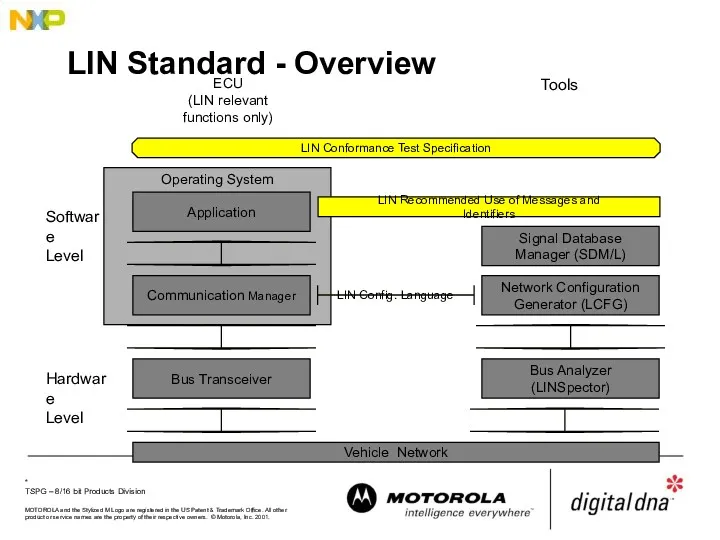
LIN Standard - Overview
Software
Level
Hardware
Level
Tools
ECU
(LIN relevant functions only)
Operating System
Bus Transceiver
Application
Communication Manager
Vehicle Network
LIN
LIN Standard - Overview
Software
Level
Hardware
Level
Tools
ECU
(LIN relevant functions only)
Operating System
Bus Transceiver
Application
Communication Manager
Vehicle Network
LIN
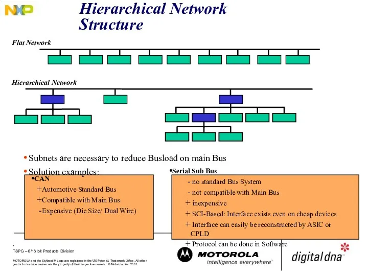
Hierarchical Network Structure
Flat Network
CAN
Automotive Standard Bus
Compatible with Main Bus
Expensive (Die Size/
Hierarchical Network Structure
Flat Network
CAN
Automotive Standard Bus
Compatible with Main Bus
Expensive (Die Size/
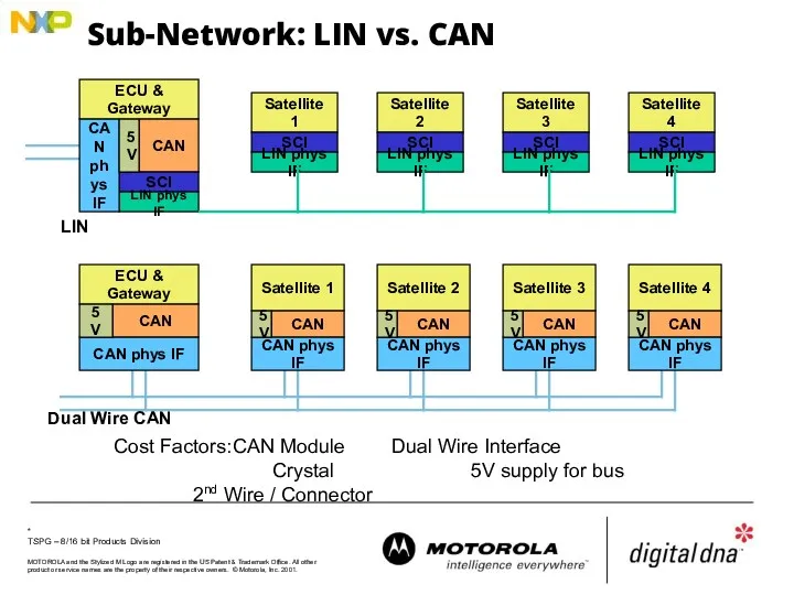
Sub-Network: LIN vs. CAN
ECU & Gateway
CAN
SCI
Satellite 1
SCI
Satellite 2
LIN phys IF
SCI
LIN phys
Sub-Network: LIN vs. CAN
ECU & Gateway
CAN
SCI
Satellite 1
SCI
Satellite 2
LIN phys IF
SCI
LIN phys
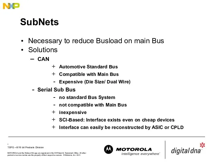
SubNets
Necessary to reduce Busload on main Bus
Solutions
CAN
Automotive Standard Bus
Compatible
SubNets
Necessary to reduce Busload on main Bus
Solutions
CAN
Automotive Standard Bus
Compatible
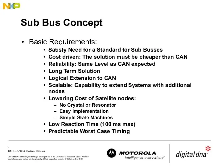
Sub Bus Concept
Basic Requirements:
Satisfy Need for a Standard for Sub Busses
Cost
Sub Bus Concept
Basic Requirements:
Satisfy Need for a Standard for Sub Busses
Cost
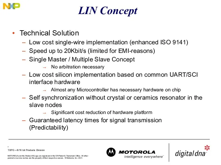
LIN Concept
Technical Solution
Low cost single-wire implementation (enhanced ISO 9141)
Speed up to
LIN Concept
Technical Solution
Low cost single-wire implementation (enhanced ISO 9141)
Speed up to
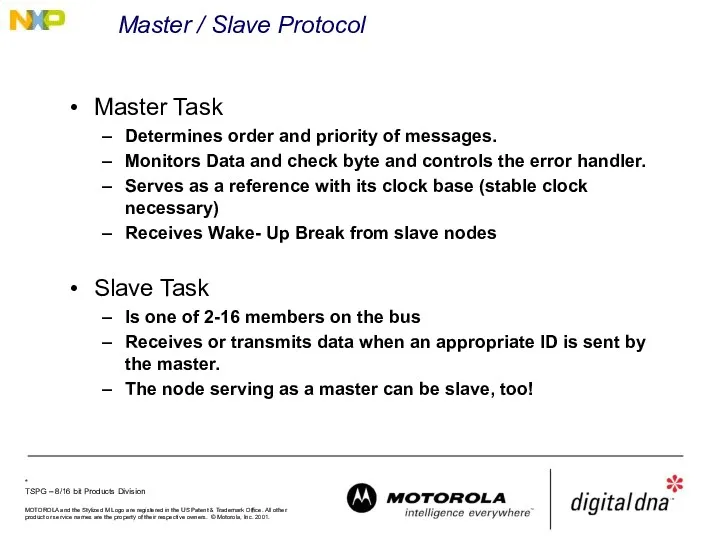
Master / Slave Protocol
Master Task
Determines order and priority of messages.
Monitors
Master / Slave Protocol
Master Task
Determines order and priority of messages.
Monitors
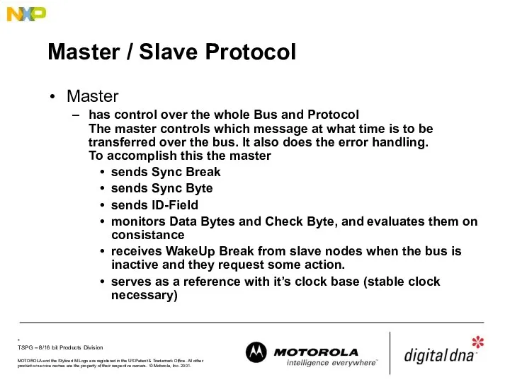
Master / Slave Protocol
Master
has control over the whole Bus and Protocol
The
Master / Slave Protocol
Master
has control over the whole Bus and Protocol
The
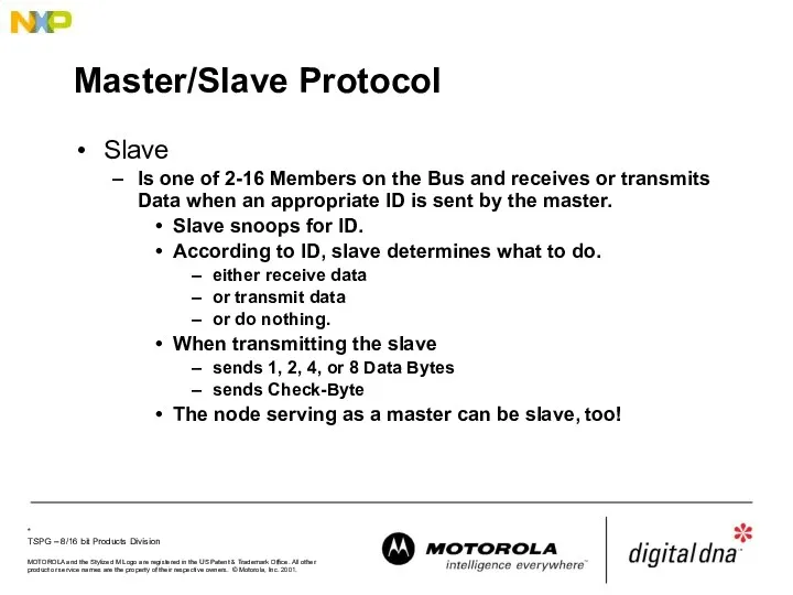
Master/Slave Protocol
Slave
Is one of 2-16 Members on the Bus and receives
Master/Slave Protocol
Slave
Is one of 2-16 Members on the Bus and receives
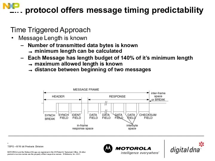
LIN protocol offers message timing predictability
Time Triggered Approach
Message Length
LIN protocol offers message timing predictability
Time Triggered Approach
Message Length
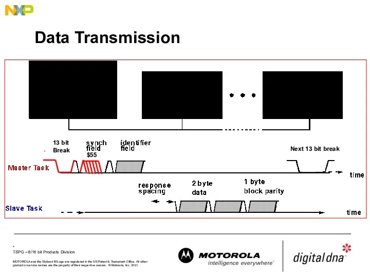
Data Transmission
Data Transmission
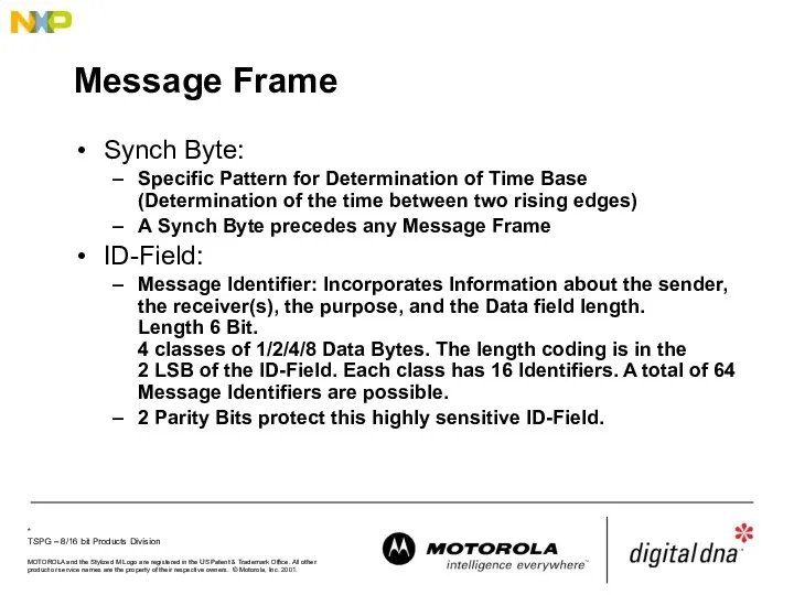
Message Frame
Synch Byte:
Specific Pattern for Determination of Time Base
(Determination of the
Message Frame
Synch Byte:
Specific Pattern for Determination of Time Base
(Determination of the
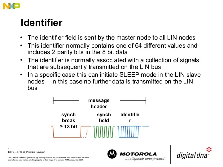
Identifier
The identifier field is sent by the master node to all
Identifier
The identifier field is sent by the master node to all
LIN Message Frame
LIN Message Frame
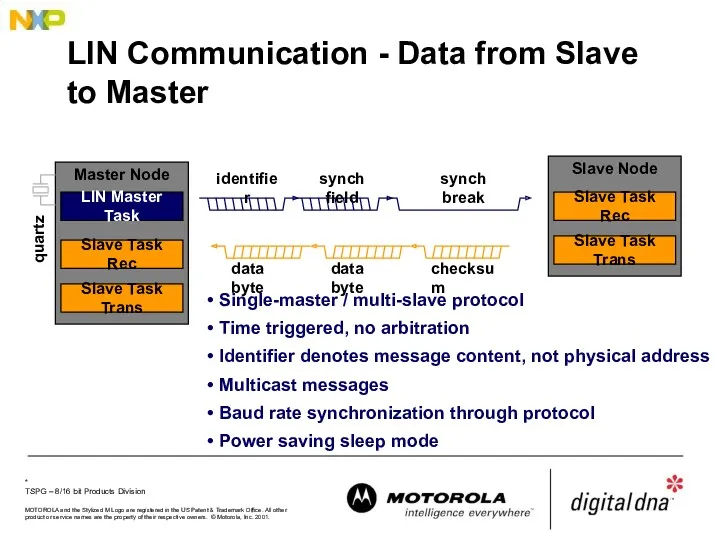
LIN Communication - Data from Slave to Master
Single-master / multi-slave protocol
Time
LIN Communication - Data from Slave to Master
Single-master / multi-slave protocol
Time
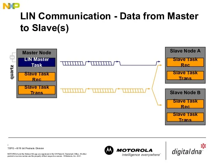
LIN Communication - Data from Master to Slave(s)
LIN Communication - Data from Master to Slave(s)
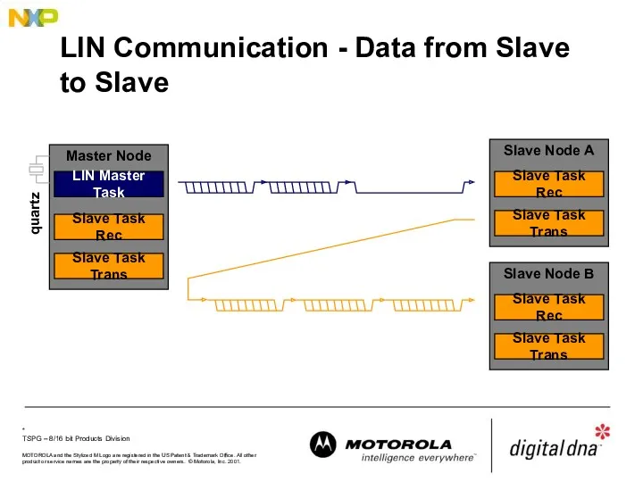
LIN Communication - Data from Slave to Slave
Slave Node A
Slave Task
LIN Communication - Data from Slave to Slave
Slave Node A
Slave Task
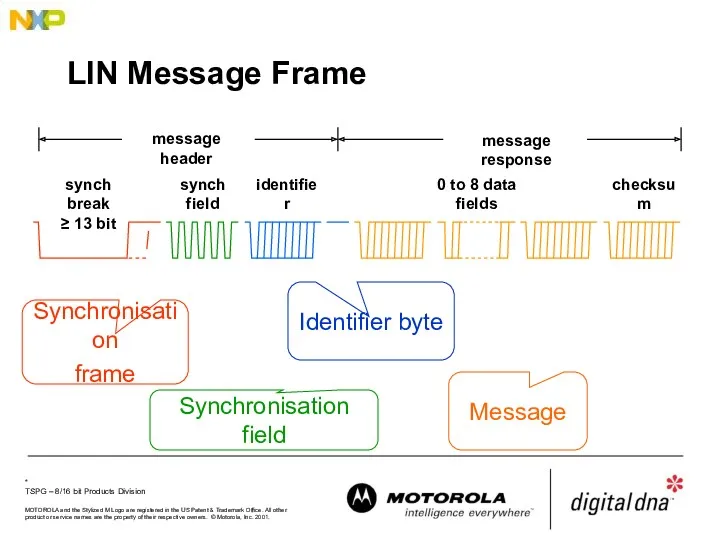
LIN Message Frame
synch break
≥ 13 bit
synch field
identifier
message header
Synchronisation
frame
Synchronisation field
Identifier byte
Message
LIN Message Frame
synch break
≥ 13 bit
synch field
identifier
message header
Synchronisation
frame
Synchronisation field
Identifier byte
Message
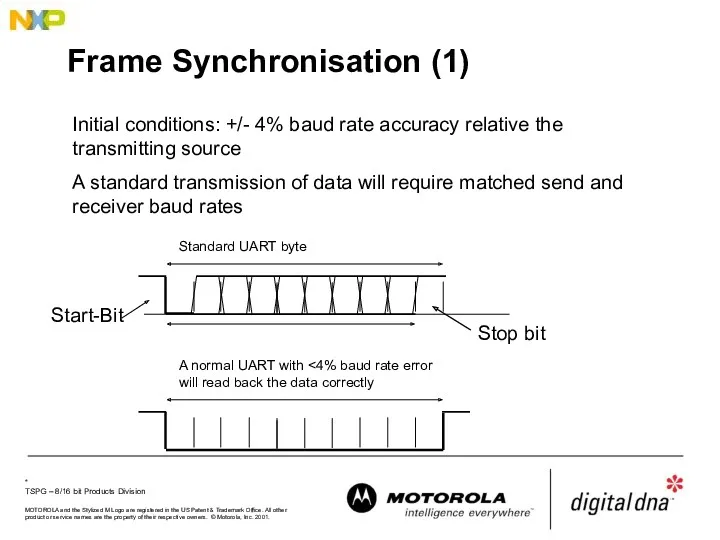
Frame Synchronisation (1)
Initial conditions: +/- 4% baud rate accuracy relative the
Frame Synchronisation (1)
Initial conditions: +/- 4% baud rate accuracy relative the
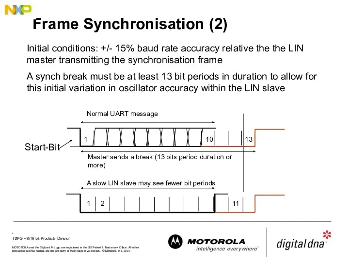
Frame Synchronisation (2)
Initial conditions: +/- 15% baud rate accuracy relative the
Frame Synchronisation (2)
Initial conditions: +/- 15% baud rate accuracy relative the
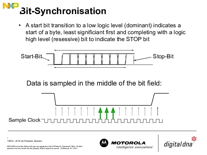
Bit-Synchronisation
A start bit transition to a low logic level (dominant) indicates
Bit-Synchronisation
A start bit transition to a low logic level (dominant) indicates
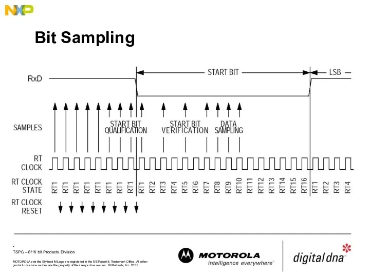
Bit Sampling
Bit Sampling
Bit-Synchronisation
After recognition of a Low level in the start bit, the
Bit-Synchronisation
After recognition of a Low level in the start bit, the
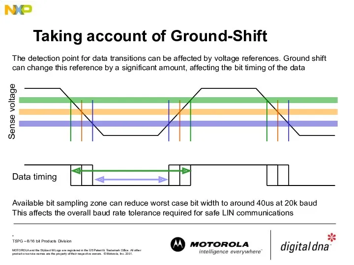
Taking account of Ground-Shift
The detection point for data transitions can be
Taking account of Ground-Shift
The detection point for data transitions can be
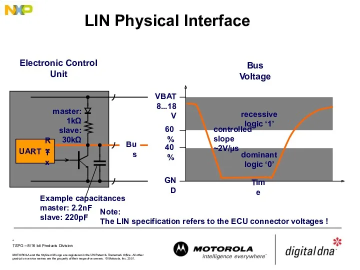
LIN Physical Interface
VBAT
8...18V
GND
UART
Rx
Tx
Electronic Control Unit
master: 1kΩ
slave: 30kΩ
Bus
controlled slope
~2V/µs
Note:
The LIN specification
LIN Physical Interface
VBAT
8...18V
GND
UART
Rx
Tx
Electronic Control Unit
master: 1kΩ
slave: 30kΩ
Bus
controlled slope
~2V/µs
Note:
The LIN specification
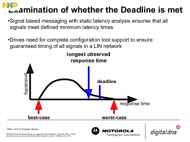
Examination of whether the Deadline is met
response time
probability
worst-case
longest observed
response time
best-case
deadline
Signal based
Examination of whether the Deadline is met
response time
probability
worst-case
longest observed
response time
best-case
deadline
Signal based
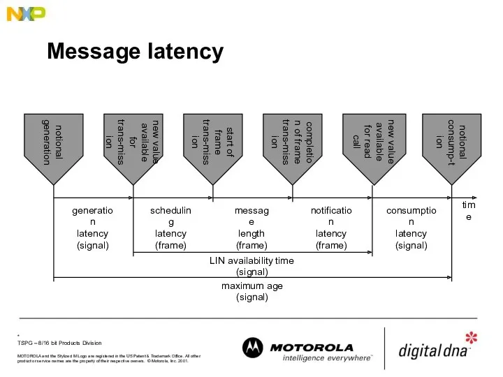
Message latency
Message latency
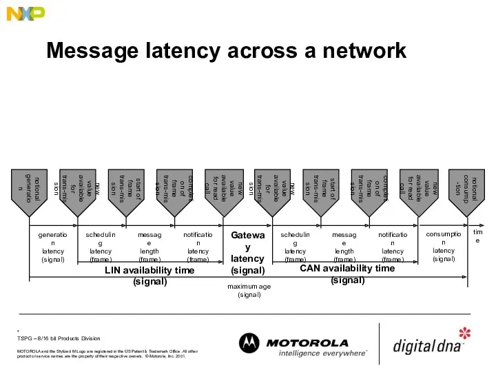
Message latency across a network
notional
generation
new value available for trans-mission
new value available
Message latency across a network
notional
generation
new value available for trans-mission
new value available
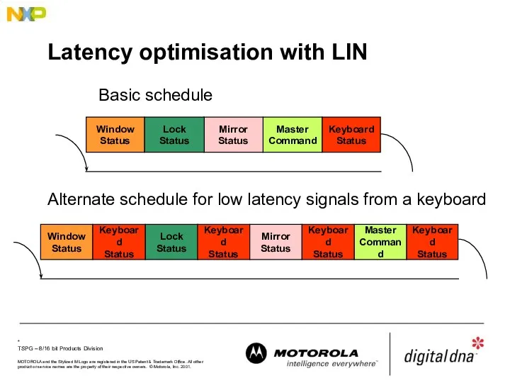
Latency optimisation with LIN
Window
Status
Master
Command
Mirror
Status
Lock
Status
Keyboard
Status
Window
Status
Lock
Status
Keyboard
Status
Keyboard
Status
Basic schedule
Alternate schedule for low latency signals from
Latency optimisation with LIN
Window
Status
Master
Command
Mirror
Status
Lock
Status
Keyboard
Status
Window
Status
Lock
Status
Keyboard
Status
Keyboard
Status
Basic schedule
Alternate schedule for low latency signals from
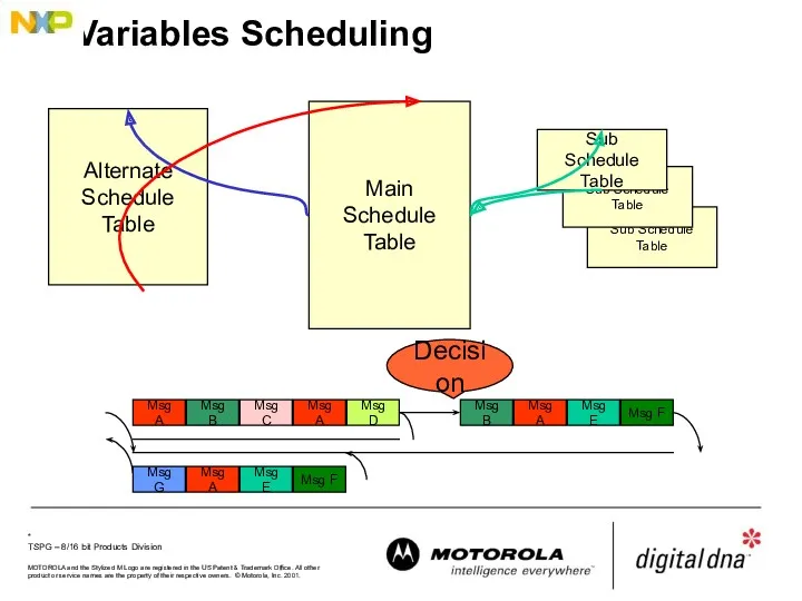
Sub Schedule Table
Variables Scheduling
Main
Schedule Table
Sub Schedule Table
Sub
Schedule Table
Alternate
Schedule
Sub Schedule Table
Variables Scheduling
Main
Schedule Table
Sub Schedule Table
Sub
Schedule Table
Alternate
Schedule
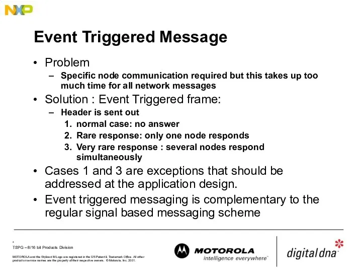
Event Triggered Message
Problem
Specific node communication required but this takes up too
Event Triggered Message
Problem
Specific node communication required but this takes up too
Further information
http://www.lin-subbus.org
- Consortium
Further information
http://www.lin-subbus.org
- Consortium
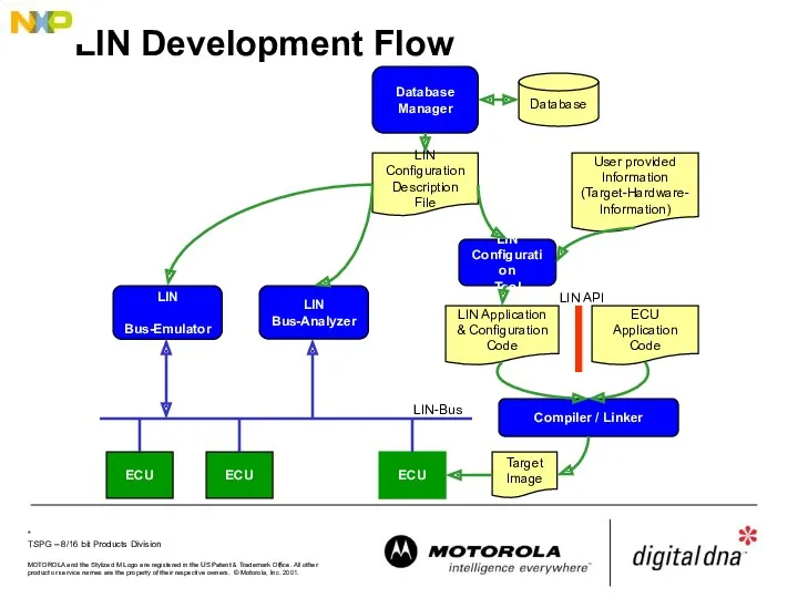
LIN Development Flow
Database
Manager
Database
LIN
Configuration
Description File
LIN
Configuration
Tool
User provided
Information
(Target-Hardware-
Information)
LIN Application
& Configuration
Code
ECU Application
Code
LIN
Bus-Analyzer
Target
Image
Compiler / Linker
LIN API
LIN-Bus
ECU
LIN
LIN Development Flow
Database
Manager
Database
LIN
Configuration
Description File
LIN
Configuration
Tool
User provided
Information
(Target-Hardware-
Information)
LIN Application
& Configuration
Code
ECU Application
Code
LIN
Bus-Analyzer
Target
Image
Compiler / Linker
LIN API
LIN-Bus
ECU
LIN
LIN Configuration Description File
Includes all essential information of network signals, latency
LIN Configuration Description File
Includes all essential information of network signals, latency
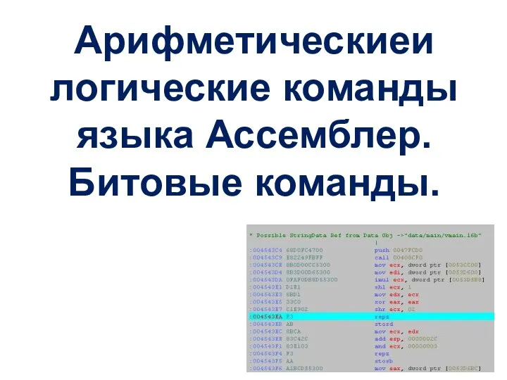 Арифметические и логические команды языка Ассемблер. Битовые команды
 ООП 4. Раннее или позднее связывание
 Информационная безопасность в системе национальной безопасности РФ. Базовые принципы обеспечения информационной безопасности
 Лекции по программированию на ассемблере
 Понятия алгебры логики, логические выражения и логические операции
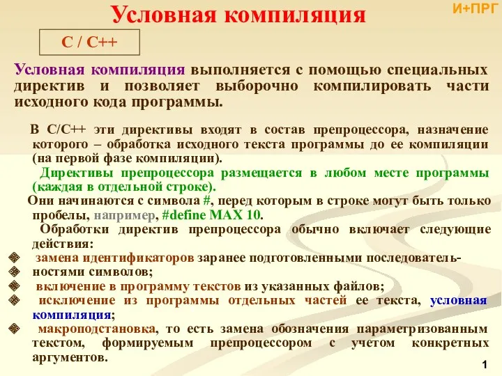 Условная компиляция
 Опасности в Интернете
 Системы автоматического управления. Основные понятия и определения
 Компьютерные сети, назначение
 Передача и хранение информации
 Етикет електронного листування. (7 клас)
 Кто миллион возьмет
 Иллюстрированные правила игры. Twilight imperium 3rd edition
 Цифровые мониторы для размещения рекламы
 Мультиагентная технология (МАТ)
 Презентация История языков программирования
 Електронні таблиці Microsoft Excel
 Современный ethernet
 Переводы чисел в десятичную позиционную систему счисления
 Представление графических данных. Форматы графических данных
 Информационные ресурсы. Этические и правовые нормы информационной деятельности
 Реляционная модель данных. (Лекция 3)
 Представление числовой информации с помощью систем счисления
 16-сабақ. Ғаламтормен дұрыс жұмыс жасау -мәдениет
 Совершенствование работы станции технического обслуживания автомобилей путем создания клиентской базы данных
 06-Understanding JavaScript and Coding Essentials
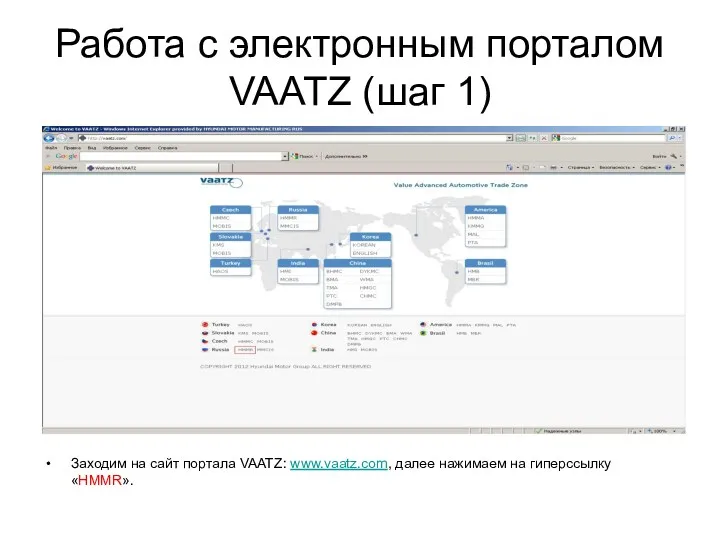 Работа с электронным порталом Vaatz
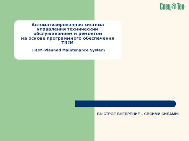 Автоматизированная система управления техническим обслуживанием и ремонтом на основе программного обеспечения TRIM