- Модель вариантов использования в Rose. (Тема 4)

Содержание
- 2. Where Are We? The why and what of a use-case model Elements of a use-case diagram
- 3. Why Create a Use-Case Model? A use-case model allows the customer and system developer to communicate
- 4. What Is a Use-Case Model? A use-case model is representation of the system’s intended functions and
- 5. Where Are We? The why and what of a use-case model Elements of a use-case diagram
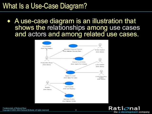
- 6. What Is a Use-Case Diagram? A use-case diagram is an illustration that shows the relationships among
- 7. A use-case diagram can be modeled in a number of ways. What Is a Use-Case Diagram?
- 8. A use case is a sequence of actions performed by the system that yields a measurable
- 9. An actor is someone or something outside the system that interacts with the system. In the
- 10. A relationship illustrates a semantic connection among model elements. In the UML, an association relationship is
- 11. Review Why create a use-case model? What are possible sources for developing a use-case diagram? What
- 12. Where Are We? The why and what of a use-case model Elements of a use-case diagram
- 13. What Is a Flow of Events? A flow of events is a text description of the
- 14. What Are Artifacts? Artifacts are documents, models, or model elements used to capture and convey project
- 15. Where Are We? The why and what of a use-case model Elements of a use-case diagram
- 16. What Is an Activity Diagram? An activity diagram in the use-case model can be used to
- 17. Activity An activity represents the performance of a task within the workflow. In the UML, an
- 18. Start State A start state explicitly shows the beginning of a workflow on an activity diagram.
- 19. End State An end state represents a final or terminal state on an activity diagram. There
- 20. State Transitions A state transition shows what activity follows after another. In the UML, a state
- 21. Decisions A decision is a point in an activity diagram where guard conditions are used to
- 22. Synchronization Bars A synchronization bar allows you to show concurrent threads in a workflow of a
- 23. Swimlanes A swimlane is used to partition an activity diagram to help us better understand who
- 25. Скачать презентацию
Where Are We?
The why and what of a use-case model
Elements of
Where Are We?
The why and what of a use-case model
Elements of
Why Create a Use-Case Model?
A use-case model allows the customer
Why Create a Use-Case Model?
A use-case model allows the customer
What Is a Use-Case Model?
A use-case model is representation
What Is a Use-Case Model?
A use-case model is representation
Where Are We?
The why and what of a use-case model
Elements of
Where Are We?
The why and what of a use-case model
Elements of
What Is a Use-Case Diagram?
A use-case diagram is an
What Is a Use-Case Diagram?
A use-case diagram is an
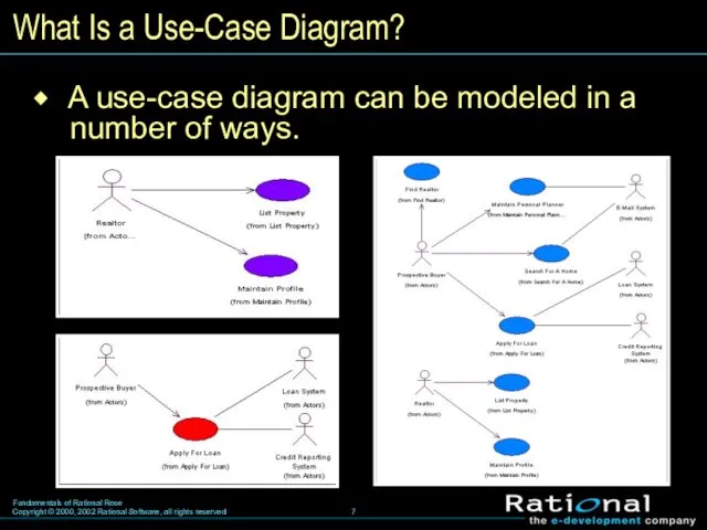
A use-case diagram can be modeled in a number of
A use-case diagram can be modeled in a number of
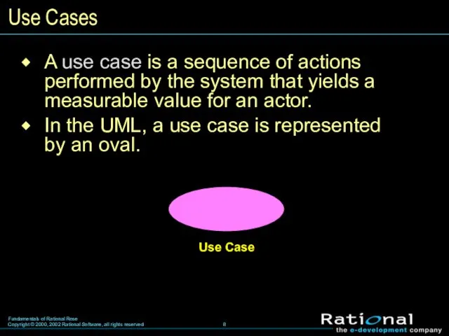
A use case is a sequence of actions performed by
A use case is a sequence of actions performed by
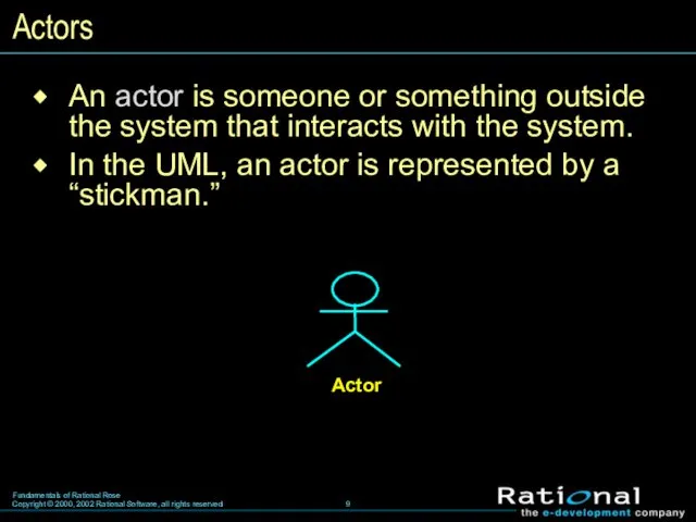
An actor is someone or something outside the system that
An actor is someone or something outside the system that
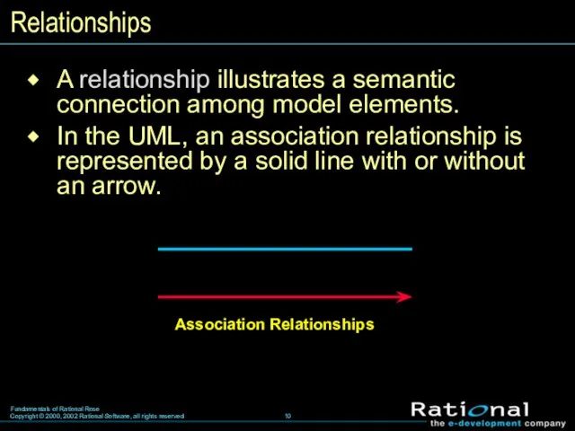
A relationship illustrates a semantic connection among model elements.
In
A relationship illustrates a semantic connection among model elements.
In
Review
Why create a use-case model?
What are possible sources for developing a
Review
Why create a use-case model?
What are possible sources for developing a
Where Are We?
The why and what of a use-case model
Elements of
Where Are We?
The why and what of a use-case model
Elements of
What Is a Flow of Events?
A flow of events
What Is a Flow of Events?
A flow of events
What Are Artifacts?
Artifacts are documents, models, or model elements
What Are Artifacts?
Artifacts are documents, models, or model elements
Where Are We?
The why and what of a use-case model
Elements of
Where Are We?
The why and what of a use-case model
Elements of
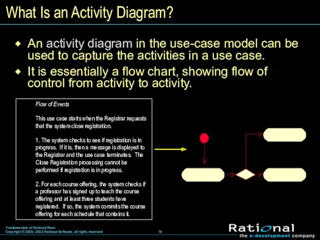
What Is an Activity Diagram?
An activity diagram in the use-case model
What Is an Activity Diagram?
An activity diagram in the use-case model
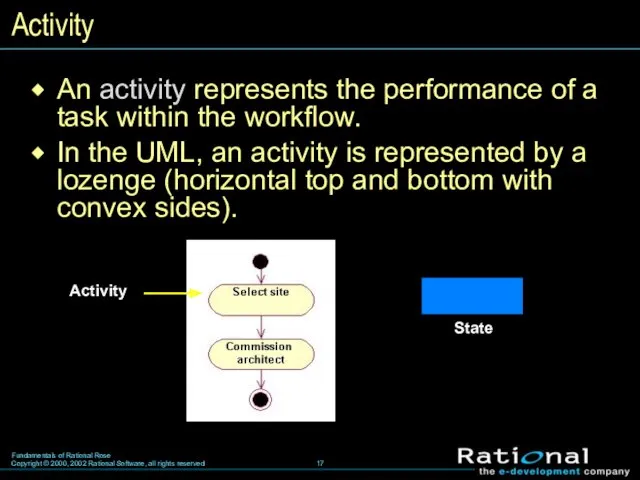
Activity
An activity represents the performance of a task within the workflow.
Activity
An activity represents the performance of a task within the workflow.
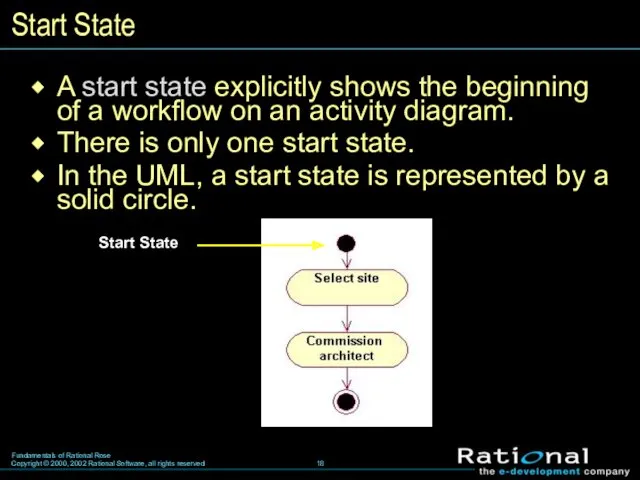
Start State
A start state explicitly shows the beginning of a workflow
Start State
A start state explicitly shows the beginning of a workflow
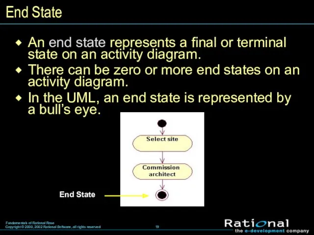
End State
An end state represents a final or terminal state on
End State
An end state represents a final or terminal state on
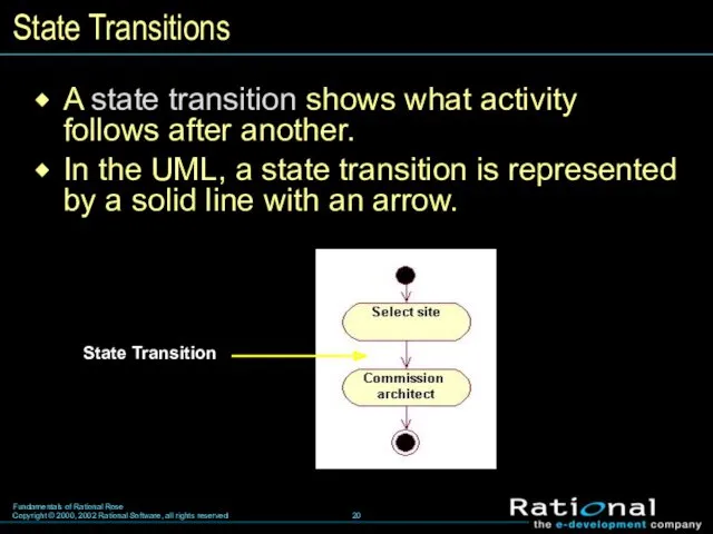
State Transitions
A state transition shows what activity follows after another.
In the
State Transitions
A state transition shows what activity follows after another.
In the
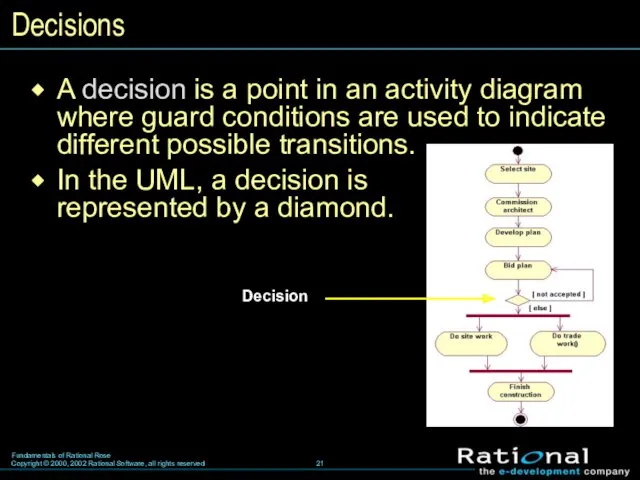
Decisions
A decision is a point in an activity diagram where guard
Decisions
A decision is a point in an activity diagram where guard
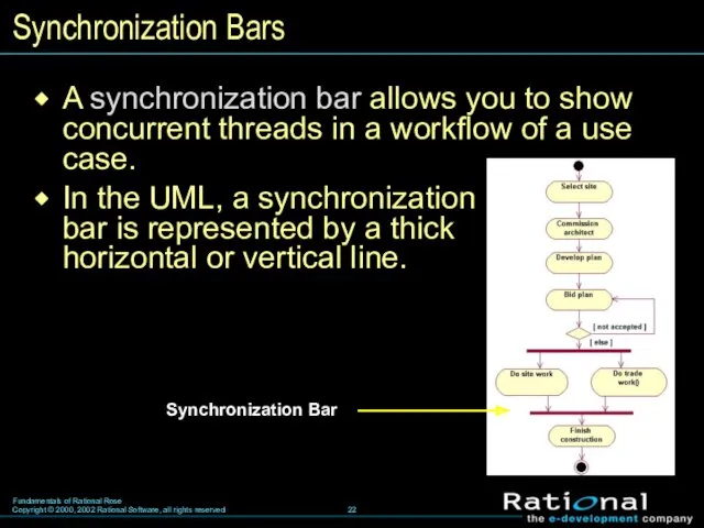
Synchronization Bars
A synchronization bar allows you to show concurrent threads in
Synchronization Bars
A synchronization bar allows you to show concurrent threads in
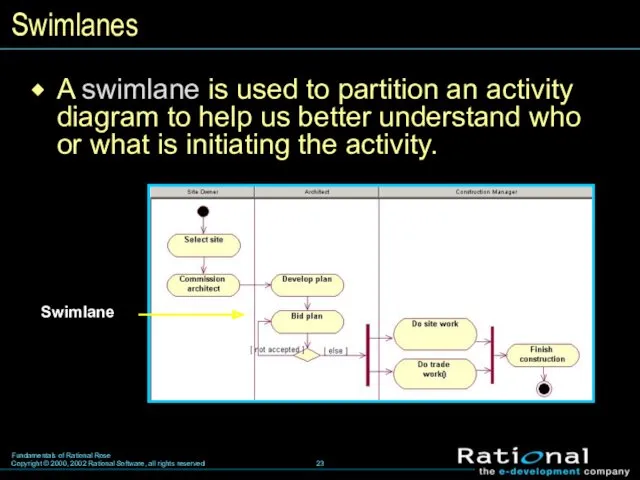
Swimlanes
A swimlane is used to partition an activity diagram to help
Swimlanes
A swimlane is used to partition an activity diagram to help
 Базы данных
 Стандарт презентации проекта
 Сто к одному. Игра
 презентация по информатике для 8 класса
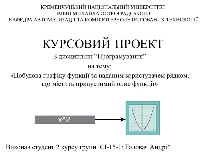 Курсовий проект. Побудова графіку функції за наданим користувачем рядком, що містить припустимий опис функції
 Портал Госуслуг gosuslugi.ru и услуга Электронный дневник
 Язык Python. Виключення
 Microsoft Word. Таблицы
 Microsoft Corporation
 Классы: основные понятия
 Компания Мелленниум Тревел. Шаблон сайта
 Введение в тестирование ПО
 CSS Grid Layout
 Алгоритми сортування
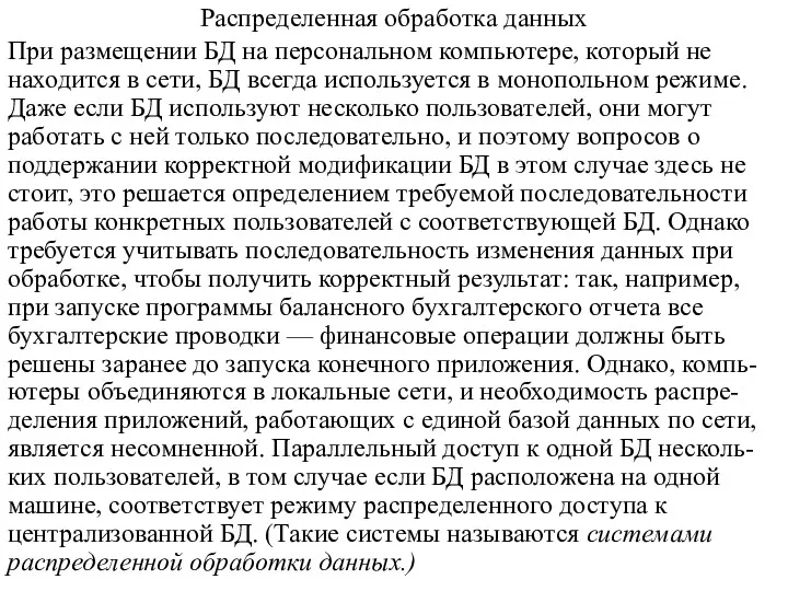 Распределенная обработка данных
 Алгоритмы
 Информация, информационные технологии
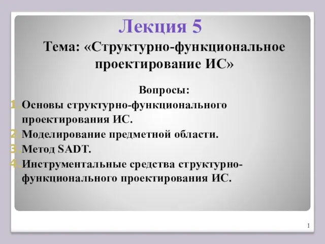 Структурно-функциональное проектирование ИС. Лекция 5
 Киберспорт и его развитие
 Ретроспектива развития человечества через развитие человеческих укладов
 Геоинформационные системы. ХХI век - век информации. ГИС - технология работы с ней
 Решение задач линейного программирования
 Роль информационной деятельности человека в современном обществе. Тема 1.1
 План-сценарий внеурочного мероприятия Безопасный Интернет
 Модели и моделирование
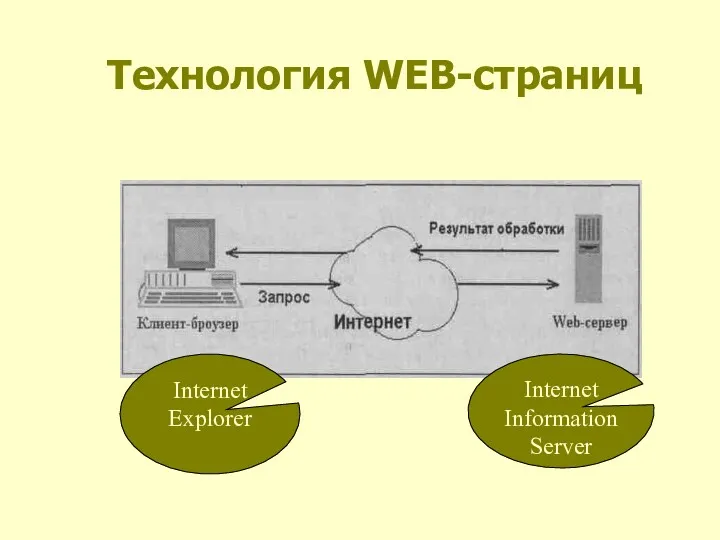 Технология WEB страниц
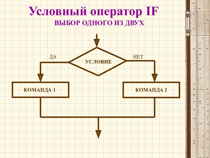 Условный оператор IF
 ЕГЭ 2015 по информатике