- Module 1 – Hardware & Installation

Содержание
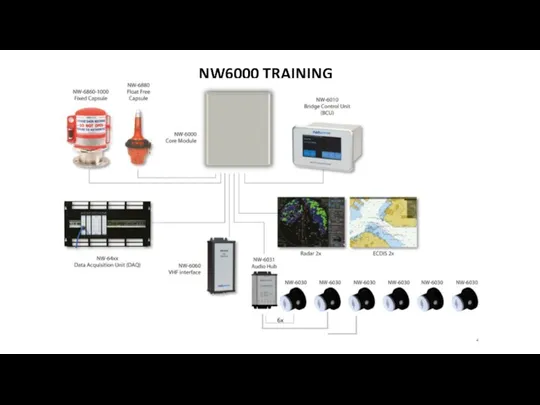
- 2. NW6000 TRAINING
- 3. INTRODUCTION Netwave started as development company for pure 2nd generation of VDRs in 2005 Headquarters and
- 4. SEASOFSOLUTIONS/NETWAVE MANUFACTURER OF VOYAGE DATA RECORDERS NW4000 developed in 2005 > obsolete installed on approx. 700
- 5. RUTTER VDR’S CANADIAN PRODUCT RETRIEVED BY NETWAVE 2011 100/G1 100/G2 100/G3
- 6. SUPPORT – HELP -APT CONTACT ADDRESSES AND PHONE NR’S To contact VDR Support: service@seasofsolutions.com To contact
- 7. STAY UPDATED, VISIT OUR PARTNER PORTAL GET YOUR USER NAME AND PASSWORD FOR ACCESS VIA OUR
- 8. OPENING THE EXTRANET LOCATION Find all last bulletins, manuals, APT forms and software for all our
- 9. NW6000 PUBLICATIONS NW6000-10 VDR Installation and Maintenance Manual NW6000-10 VDR Operator Manual APT Checklist form (see
- 10. QUESTIONS?
- 11. NW6000 SINGLE LINE DIAGRAM >AUGUST2020 NEW!
- 12. NW6000 SINGLE LINE DIAGRAM OLD!
- 13. NW6000 WIRING DIAGRAM
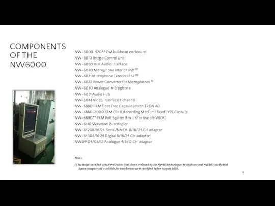
- 14. COMPONENTS OF THE NW6000 NW-6000-920** CM bulkhead enclosure NW-6010 Bridge Control Unit NW-6060 VHF Audio Interface
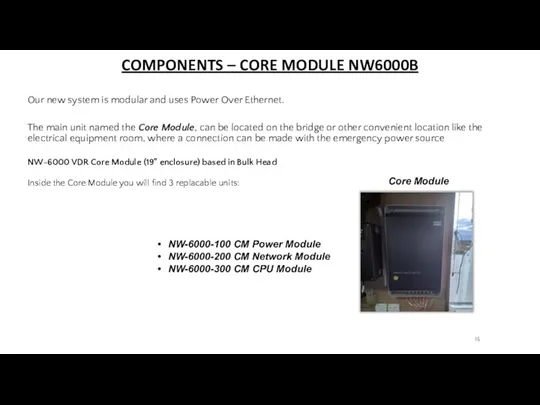
- 15. COMPONENTS – CORE MODULE NW6000B Our new system is modular and uses Power Over Ethernet. The
- 16. DIMENSIONS
- 17. COMPONENTS – CORE MODULE VDR ENCLOSURE 19” The VDR 19”enclosure can be taken out of the
- 18. COMPONENTS – VDR CORE MODULE (19” ENCLOSURE) The Core Module combines 3 functions from 3 independent
- 19. COMPONENTS – POWER SUPPLY MODULE Led indication on Power Module Normal function 110V/230V power connected: Green
- 20. INSTALLATION – POWER SUPPLY MODULE CONNECTION The Power Supply should be connected via the delivered filter
- 21. COMPONENTS – POWER SUPPLY MODULE The CM Power modules also serves to provide an external CAUTION
- 22. COMPONENTS – NETWORK SWITCH The Network Switch has 8x PoE RJ45 network connectors and 2 ‘normal’
- 23. COMPONENTS – NETWORK SWITCH Green Off Ethernet link not established. Either the RJ-45 cable is unplugged
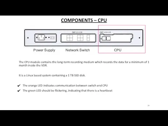
- 24. COMPONENTS – CPU The CPU module contains the long-term recording medium which records the data for
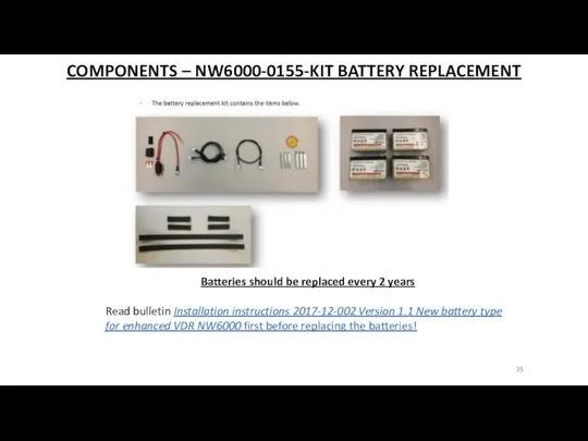
- 25. COMPONENTS – NW6000-0155-KIT BATTERY REPLACEMENT Batteries should be replaced every 2 years Read bulletin Installation instructions
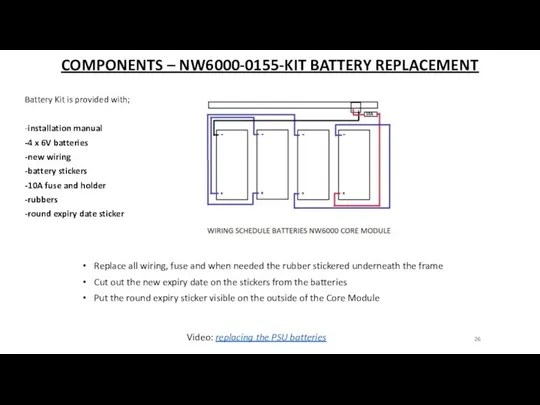
- 26. COMPONENTS – NW6000-0155-KIT BATTERY REPLACEMENT Battery Kit is provided with; -installation manual -4 x 6V batteries
- 27. QUESTIONS?
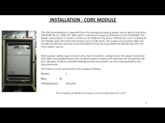
- 28. INSTALLATION - CORE MODULE The CM (Core Module) is powered from the emergency backup power source
- 29. INSTALLATION CORE MODULE – MOUNTING If the bulkhead-mounting enclosure is used, mount the bracket with your
- 30. INSTALLATION - CORE MODULE NETWORK CONNECTIONS TO THE DIFFERENT MODULES AND FRM’S ARE MADE ON THE
- 31. INSTALLATION - CORE MODULE EXAMPLES
- 32. COMPONENTS – BCU (BRIDGE CONTROL UNIT) NW6010 BCU The Bridge Control Unit (BCU) is the operating
- 33. BCU DIMENSIONS
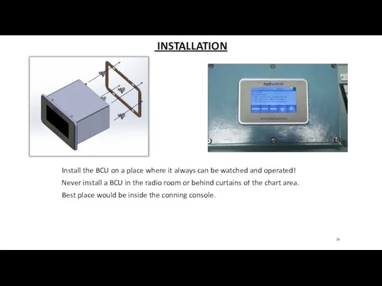
- 34. INSTALLATION Install the BCU on a place where it always can be watched and operated! Never
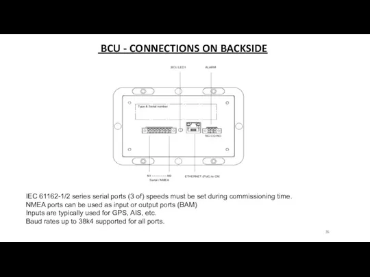
- 35. BCU - CONNECTIONS ON BACKSIDE IEC 61162-1/2 series serial ports (3 of) speeds must be set
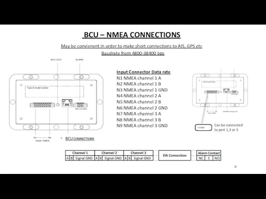
- 36. BCU – NMEA CONNECTIONS Input Connector Data rate N1 NMEA channel 1 A N2 NMEA channel
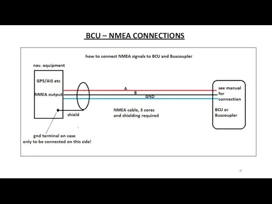
- 37. BCU – NMEA CONNECTIONS
- 38. BCU – CENTRAL ALARM PANEL CONNECTION Central Alarm Panel (contacts) can be connected via BCU or
- 39. BCU – COMMUNICATION AND POWER The BCU has 1 green LED to indicate that the power
- 40. BCU – ERROR INDICATION In the event the LED on the back side of the unit
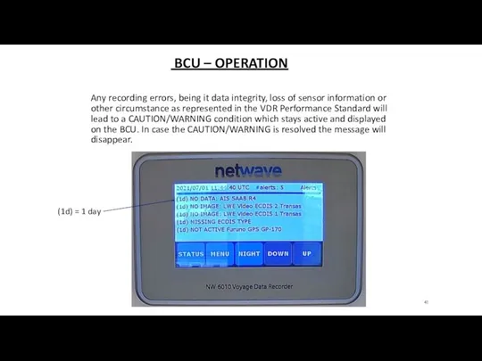
- 41. BCU – OPERATION Any recording errors, being it data integrity, loss of sensor information or other
- 42. BCU – UNITS OR DEVICES (WARNING) In the event of network-absence or malfunction of any hardware
- 43. BCU – OPERATIONAL PERFORMANCE TEST Can be conducted on the BCU Will test all incoming signals
- 44. QUESTIONS?
- 45. COMPONENTS – NW6860 (FRM) FIXED HSS CAPSULE NW6880 FFC TRON40 VDR FLOAT FREE CAPSULE Requirement from
- 46. COMPONENTS – NW-6860 (FRM) FIXED HSS CAPSULE Fully meets IMO Resolution A.861(20) and all applicable Safety
- 47. NW-6860 DIMENSIONS Mounting Plate included for retrofit or welding
- 48. COMPONENTS – NW6860 FIXED CAPSULE MEMORY CAPACITY 64GB The capsule shall be positioned clear of rigging
- 49. COMPONENTS – INDICATORS When in unassembled state (and viewed from the bottom of the capsule part)
- 50. INSTALLATION – DECKMOUNT ASSEMBLY Mounting plate Choose the right position on the monkey deck Weld or
- 51. INSTALLATION – CABLING Cable through bottom Cable through side,and goose neck USE ONLY APPROVED CAT7 CABLING
- 52. INSTALLATION – CABLING Cable through bottom Cable through side, and goose neck WIRE STRIPPER Video: installing
- 53. INSTALLATION – ULB PT9 NINETY The HSS has an externally mounted underwater location beacon (ULB) with
- 54. MAINTENANCE – ULB NW4860-695 The ULB battery should be replaced after 3 years. Battery kit NW4860-693
- 55. PROCEDURE – ULB NW4860-695 Take the ULB from the capsule Replace the battery with the battery
- 56. QUESTIONS?
- 57. COMPONENTS –NW6880 FRM FLOAT FREE CAPSULE JOTRON TRON 40 Bracket MKI Bracket MKII >feb 2018
- 58. DIMENSIONS
- 59. COMPONENTS –NW6880 FRM FLOAT FREE CAPSULE JOTRON TRON 40 The location of automatically activated EPIRBs should
- 60. INSTALLATION –NW6880 FRM FLOAT FREE CAPSULE JOTRON TRON 40 - It is not recommended to locate
- 61. INSTALLATION – CABLING USE ONLY APPROVED CAT7 CABLING & CONNECTORS ORDER VIA SALES@SEASOFSOLUTIONS.COM
- 62. INSTALLATION – HARDWARE MOUNT THE TRON40 ON A STEEL PLATE AND INSTALL IT IN VERTICAL POSITION
- 63. INSTALLATION – CONNECTIONS FOR MKI
- 64. INSTALLATION – CONNECTIONS FOR MKII OR:
- 65. INSTALLATION – CONNECTIONS Use ferrules to make a solid and good electrical connection, ground the cable
- 66. INSTALLATION – LOCATION The location of automatically activated EPIRBs should ideally be sited in a clear
- 67. LED INDICATION – BRACKET Green LED’s identification on the bracket explained: Bracket MKI Bracket MKII >feb
- 68. QUESTIONS?
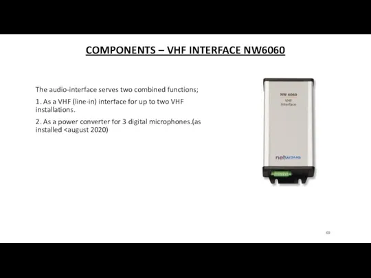
- 69. COMPONENTS – VHF INTERFACE NW6060 The audio-interface serves two combined functions; 1. As a VHF (line-in)
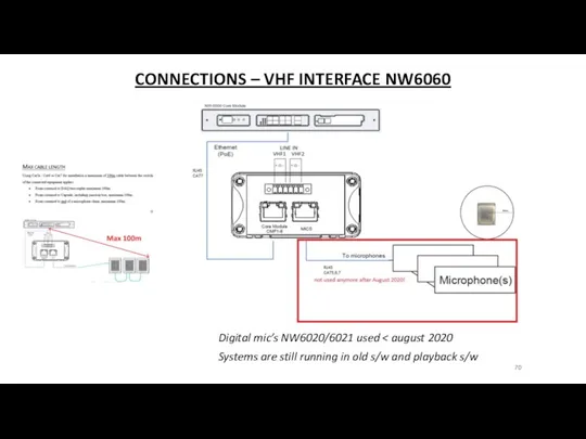
- 70. CONNECTIONS – VHF INTERFACE NW6060 Digital mic’s NW6020/6021 used Systems are still running in old s/w
- 71. CONNECTIONS – VHF INTERFACE NW6060 WITH OLD DIGITAL MIC’S 1. The NW-6060 VHF / Audio Interface
- 72. COMPONENTS – POWER CONVERTER NW6022 The power converter (installed was used as a power converter for
- 73. COMPONENTS – CONFIGURATION The individual microphone and VHF channel’s IP-addresses are set during commissioning time. Please
- 74. COMPONENTS – NW 6020/6021 IN AND OUTDOOR MICROPHONES AS INSTALLED The microphones are of a sea-water
- 75. COMPONENTS – NW 6020/6021 IN AND OUTDOOR MICROPHONES DIGITAL ‘OLD STYLE’ The microphone has a multi-color
- 76. MOUNTING – NW 6020/6021 ‘DIGI’ IN AND OUTDOOR MICROPHONES Remove the rubber gland which is covering
- 77. MOUNTING – NW 6020/6021 IN AND OUTDOOR MICROPHONES EXAMPLES AS INSTALLED Examples from installed old style
- 78. QUESTIONS?
- 79. AUDIO COMPONENTS – NW-6031-B AUDIO HUB (FROM > AUG 2020) The Audio Hub is contained in
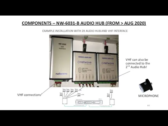
- 80. COMPONENTS – NW-6031-B AUDIO HUB (FROM > AUG 2020) EXAMPLE INSTALLATION WITH 2X AUDIO HUB AND
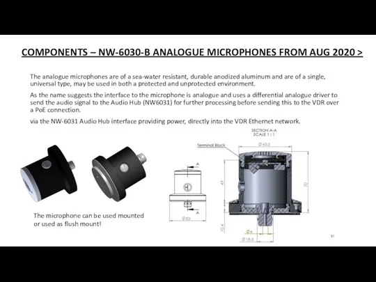
- 81. COMPONENTS – NW-6030-B ANALOGUE MICROPHONES FROM AUG 2020 > The analogue microphones are of a sea-water
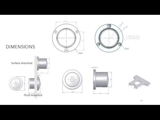
- 82. DIMENSIONS Surface mounted Flush mounted
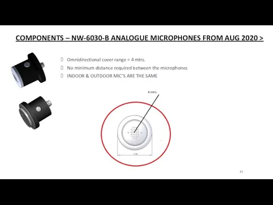
- 83. COMPONENTS – NW-6030-B ANALOGUE MICROPHONES FROM AUG 2020 > Omnidirectional cover range = 4 mtrs. No
- 84. The microphone has a green led built within the enclosure which is only visible and may
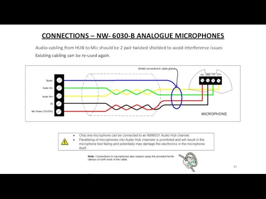
- 85. CONNECTIONS – NW- 6030-B ANALOGUE MICROPHONES Audio-cabling from HUB to Mic should be 2 pair twisted
- 86. CONNECTIONS – NW- 6030-B VHF CONNECTION Audio-cabling from HUB to VHF should be 1 pair twisted
- 87. INSTALLATION – NW- 6030-B ANALOGUE MICROPHONES Mounted outside mic Outdoor mic Flush mounted indoor mic Mounted
- 88. QUESTIONS?
- 89. COMPONENTS – NW64XXX DAQ = NMEA, DIGI AND ANALOGUE INTERFACE MODULE The DAQ system relies on
- 90. COMPONENTS – NW64XXX DAQ-DATA ACQUISITION UNIT NMEA, Analogue and Digital connections can be made to the
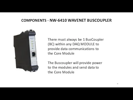
- 91. COMPONENTS - NW-6410 WAVENET BUSCOUPLER There must always be 1 BusCoupler (BC) within any DAQ MODULE
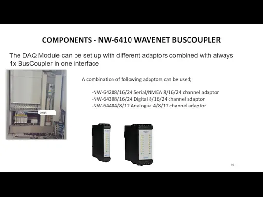
- 92. COMPONENTS - NW-6410 WAVENET BUSCOUPLER The DAQ Module can be set up with different adaptors combined
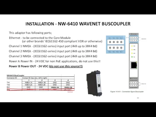
- 93. INSTALLATION - NW-6410 WAVENET BUSCOUPLER This adaptor has following ports; Ethernet - to be connected to
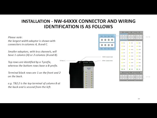
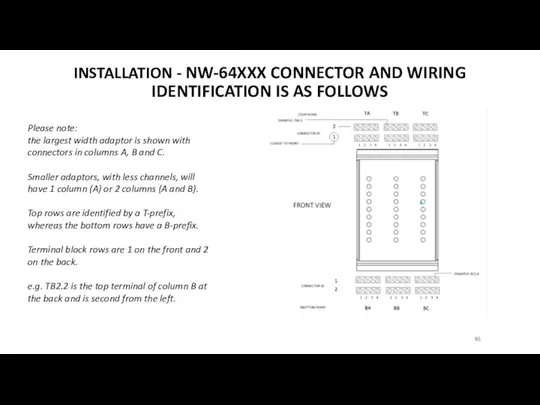
- 94. INSTALLATION - NW-64XXX CONNECTOR AND WIRING IDENTIFICATION IS AS FOLLOWS Please note: the largest width adaptor
- 95. INSTALLATION - NW-64XXX CONNECTOR AND WIRING IDENTIFICATION IS AS FOLLOWS Please note: the largest width adaptor
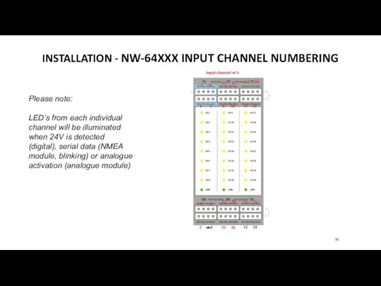
- 96. INSTALLATION - NW-64XXX INPUT CHANNEL NUMBERING Please note: LED’s from each individual channel will be illuminated
- 97. INSTALLATION - NW-64208/16/24 SERIAL/ NMEA 8/16/24 CHANNEL ADAPTORS These adaptor provide input ports for serial /
- 98. INSTALLATION -NW-64308/16/24 DIGITAL 8/16/24 CHANNEL ADAPTORS ON level 5-24V DC, max. input current 1mA. The modules
- 99. INSTALLATION -NW-64408 ANALOGUE 4-8-12 INPUT CHANNEL ADAPTOR These adaptors send analogue data (-10V/10V or 0-20mA) they
- 100. QUESTIONS?
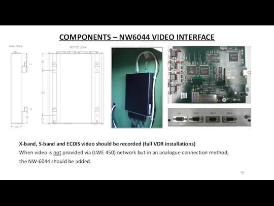
- 101. COMPONENTS – NW6044 VIDEO INTERFACE X-band, S-band and ECDIS video should be recorded (full VDR installations)
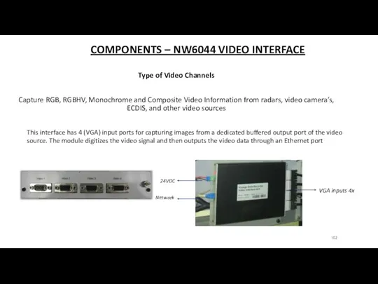
- 102. COMPONENTS – NW6044 VIDEO INTERFACE Type of Video Channels Capture RGB, RGBHV, Monochrome and Composite Video
- 103. INSTALLATION – NW6044 VIDEO INTERFACE Video: video interface DC power cable connected to a 24Vdc power
- 104. QUESTIONS?
- 106. Скачать презентацию
NW6000 TRAINING
NW6000 TRAINING
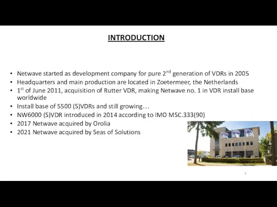
INTRODUCTION
Netwave started as development company for pure 2nd generation of VDRs
INTRODUCTION
Netwave started as development company for pure 2nd generation of VDRs
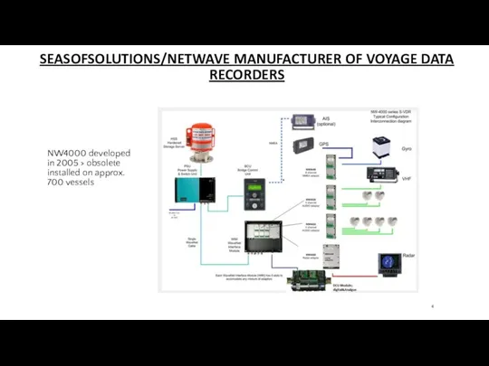
SEASOFSOLUTIONS/NETWAVE MANUFACTURER OF VOYAGE DATA RECORDERS
NW4000 developed in 2005 > obsolete
SEASOFSOLUTIONS/NETWAVE MANUFACTURER OF VOYAGE DATA RECORDERS
NW4000 developed in 2005 > obsolete
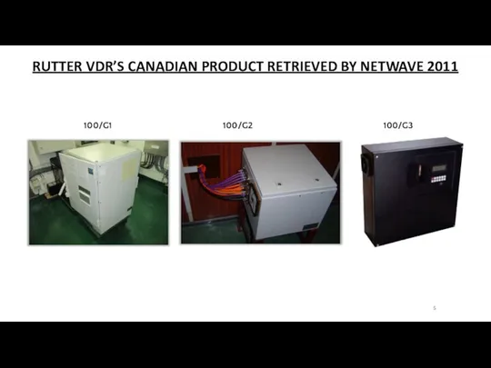
RUTTER VDR’S CANADIAN PRODUCT RETRIEVED BY NETWAVE 2011
100/G1
100/G2
100/G3
RUTTER VDR’S CANADIAN PRODUCT RETRIEVED BY NETWAVE 2011
100/G1
100/G2
100/G3
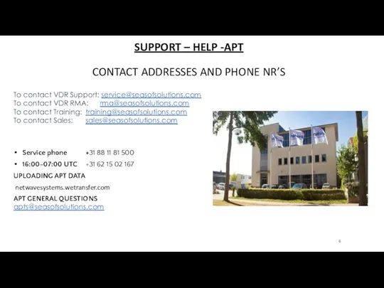
SUPPORT – HELP -APT
CONTACT ADDRESSES AND PHONE NR’S
To contact VDR Support:
SUPPORT – HELP -APT
CONTACT ADDRESSES AND PHONE NR’S
To contact VDR Support:

STAY UPDATED, VISIT OUR PARTNER PORTAL
GET YOUR USER NAME AND PASSWORD
STAY UPDATED, VISIT OUR PARTNER PORTAL GET YOUR USER NAME AND PASSWORD
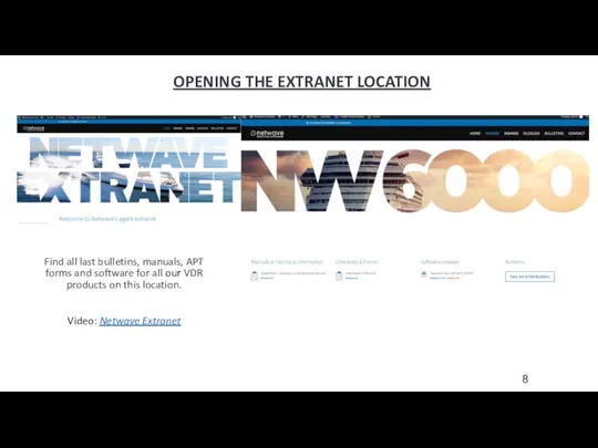
OPENING THE EXTRANET LOCATION
Find all last bulletins, manuals, APT forms and
OPENING THE EXTRANET LOCATION
Find all last bulletins, manuals, APT forms and
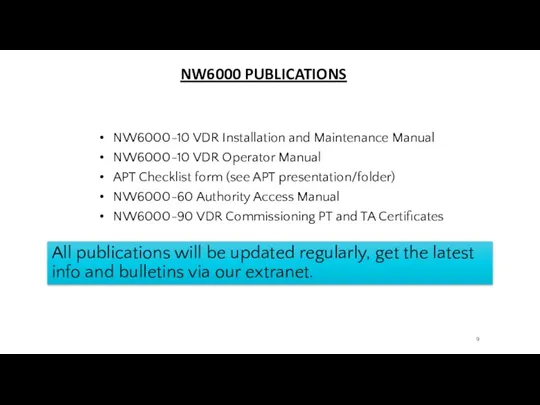
NW6000 PUBLICATIONS
NW6000-10 VDR Installation and Maintenance Manual
NW6000-10 VDR Operator Manual
APT Checklist
NW6000 PUBLICATIONS
NW6000-10 VDR Installation and Maintenance Manual
NW6000-10 VDR Operator Manual
APT Checklist

QUESTIONS?
QUESTIONS?
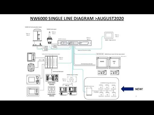
NW6000 SINGLE LINE DIAGRAM >AUGUST2020
NEW!
NW6000 SINGLE LINE DIAGRAM >AUGUST2020
NEW!
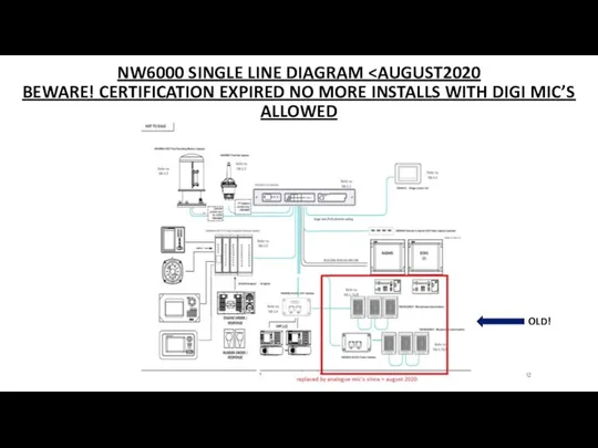
NW6000 SINGLE LINE DIAGRAM
NW6000 SINGLE LINE DIAGRAM
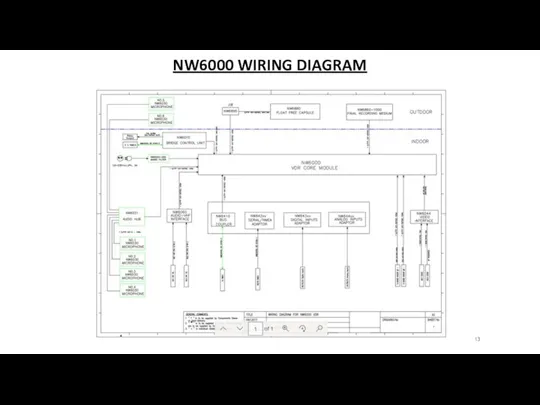
NW6000 WIRING DIAGRAM
NW6000 WIRING DIAGRAM
COMPONENTS
OF THE
NW6000
NW-6000-920** CM bulkhead enclosure
NW-6010 Bridge Control Unit
NW-6060
COMPONENTS
OF THE
NW6000
NW-6000-920** CM bulkhead enclosure
NW-6010 Bridge Control Unit
NW-6060
COMPONENTS – CORE MODULE NW6000B
Our new system is modular and uses
COMPONENTS – CORE MODULE NW6000B
Our new system is modular and uses
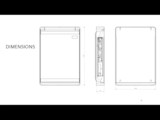
DIMENSIONS
DIMENSIONS
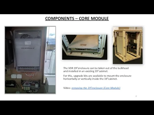
COMPONENTS – CORE MODULE
VDR ENCLOSURE 19”
The VDR 19”enclosure can be
COMPONENTS – CORE MODULE
VDR ENCLOSURE 19”
The VDR 19”enclosure can be
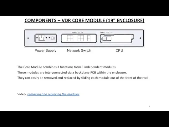
COMPONENTS – VDR CORE MODULE (19” ENCLOSURE)
The Core Module combines 3
COMPONENTS – VDR CORE MODULE (19” ENCLOSURE)
The Core Module combines 3
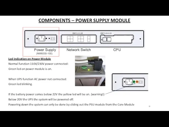
COMPONENTS – POWER SUPPLY MODULE
Led indication on Power Module
Normal
COMPONENTS – POWER SUPPLY MODULE
Led indication on Power Module
Normal
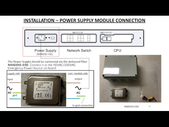
INSTALLATION – POWER SUPPLY MODULE CONNECTION
The Power Supply should be
INSTALLATION – POWER SUPPLY MODULE CONNECTION
The Power Supply should be
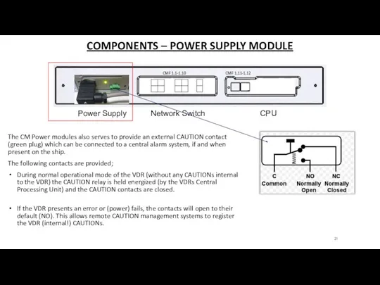
COMPONENTS – POWER SUPPLY MODULE
The CM Power modules also serves to
COMPONENTS – POWER SUPPLY MODULE
The CM Power modules also serves to
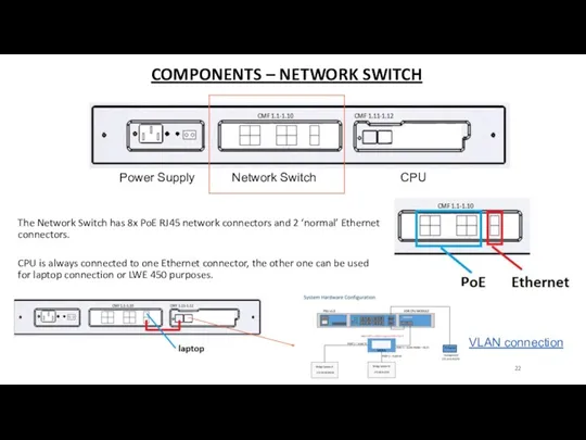
COMPONENTS – NETWORK SWITCH
The Network Switch has 8x PoE RJ45 network
COMPONENTS – NETWORK SWITCH
The Network Switch has 8x PoE RJ45 network
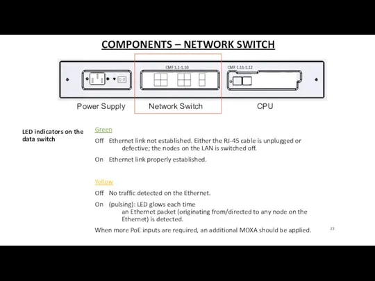
COMPONENTS – NETWORK SWITCH
Green
Off Ethernet link not established. Either the
COMPONENTS – NETWORK SWITCH
Green
Off Ethernet link not established. Either the
COMPONENTS – CPU
The CPU module contains the long-term recording medium which
COMPONENTS – CPU
The CPU module contains the long-term recording medium which
COMPONENTS – NW6000-0155-KIT BATTERY REPLACEMENT
Batteries should be replaced every 2
COMPONENTS – NW6000-0155-KIT BATTERY REPLACEMENT
Batteries should be replaced every 2
COMPONENTS – NW6000-0155-KIT BATTERY REPLACEMENT
Battery Kit is provided with;
-installation manual
-4
COMPONENTS – NW6000-0155-KIT BATTERY REPLACEMENT
Battery Kit is provided with;
-installation manual
-4

QUESTIONS?
QUESTIONS?
INSTALLATION - CORE MODULE
The CM (Core Module) is powered
INSTALLATION - CORE MODULE
The CM (Core Module) is powered
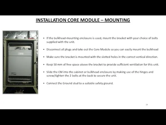
INSTALLATION CORE MODULE – MOUNTING
If the bulkhead-mounting enclosure is used,
INSTALLATION CORE MODULE – MOUNTING
If the bulkhead-mounting enclosure is used,
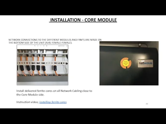
INSTALLATION - CORE MODULE
NETWORK CONNECTIONS TO THE DIFFERENT MODULES
INSTALLATION - CORE MODULE
NETWORK CONNECTIONS TO THE DIFFERENT MODULES
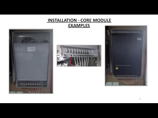
INSTALLATION - CORE MODULE
EXAMPLES
INSTALLATION - CORE MODULE
EXAMPLES
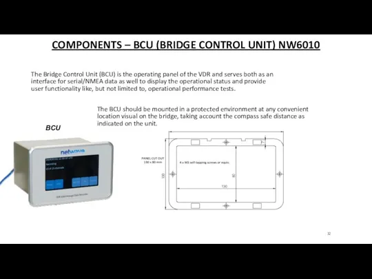
COMPONENTS – BCU (BRIDGE CONTROL UNIT) NW6010
BCU
The Bridge Control Unit (BCU)
COMPONENTS – BCU (BRIDGE CONTROL UNIT) NW6010
BCU
The Bridge Control Unit (BCU)
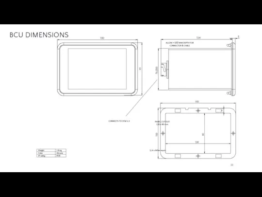
BCU DIMENSIONS
BCU DIMENSIONS
INSTALLATION
Install the BCU on a place where it
INSTALLATION
Install the BCU on a place where it
BCU - CONNECTIONS ON BACKSIDE
IEC 61162-1/2 series serial
BCU - CONNECTIONS ON BACKSIDE
IEC 61162-1/2 series serial
BCU – NMEA CONNECTIONS
Input Connector Data rate
N1
BCU – NMEA CONNECTIONS
Input Connector Data rate
N1
BCU – NMEA CONNECTIONS
BCU – NMEA CONNECTIONS
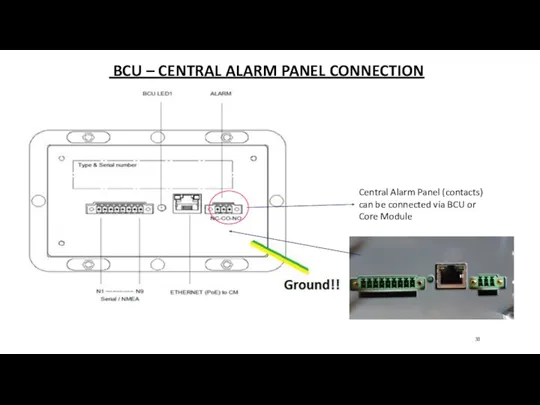
BCU – CENTRAL ALARM PANEL CONNECTION
Central Alarm Panel
BCU – CENTRAL ALARM PANEL CONNECTION
Central Alarm Panel
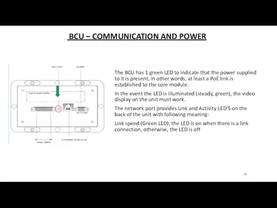
BCU – COMMUNICATION AND POWER
The BCU has 1
BCU – COMMUNICATION AND POWER
The BCU has 1
BCU – ERROR INDICATION
In the event the LED
BCU – ERROR INDICATION
In the event the LED
BCU – OPERATION
Any recording errors, being it data
BCU – OPERATION
Any recording errors, being it data
BCU – UNITS OR DEVICES (WARNING)
In the event
BCU – UNITS OR DEVICES (WARNING)
In the event
BCU – OPERATIONAL PERFORMANCE TEST
Can be conducted on
BCU – OPERATIONAL PERFORMANCE TEST
Can be conducted on

QUESTIONS?
QUESTIONS?
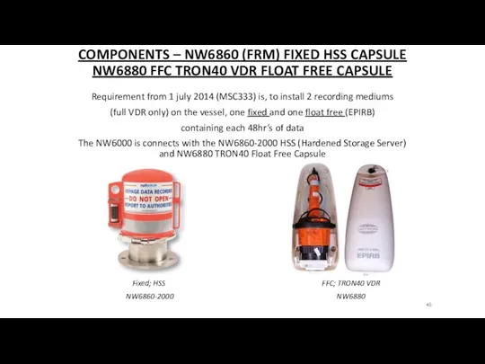
COMPONENTS – NW6860 (FRM) FIXED HSS CAPSULE
NW6880 FFC TRON40 VDR FLOAT
COMPONENTS – NW6860 (FRM) FIXED HSS CAPSULE NW6880 FFC TRON40 VDR FLOAT
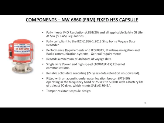
COMPONENTS – NW-6860 (FRM) FIXED HSS CAPSULE
Fully meets IMO Resolution A.861(20)
COMPONENTS – NW-6860 (FRM) FIXED HSS CAPSULE
Fully meets IMO Resolution A.861(20)
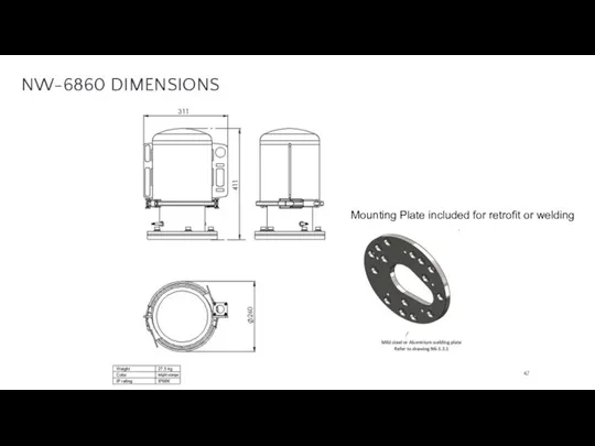
NW-6860 DIMENSIONS
Mounting Plate included for retrofit or welding
NW-6860 DIMENSIONS
Mounting Plate included for retrofit or welding
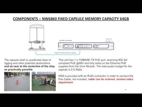
COMPONENTS – NW6860 FIXED CAPSULE MEMORY CAPACITY 64GB
The capsule shall be
COMPONENTS – NW6860 FIXED CAPSULE MEMORY CAPACITY 64GB
The capsule shall be
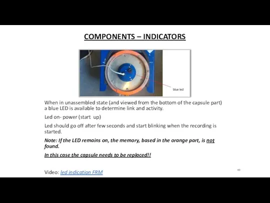
COMPONENTS – INDICATORS
When in unassembled state (and viewed from the bottom
COMPONENTS – INDICATORS
When in unassembled state (and viewed from the bottom
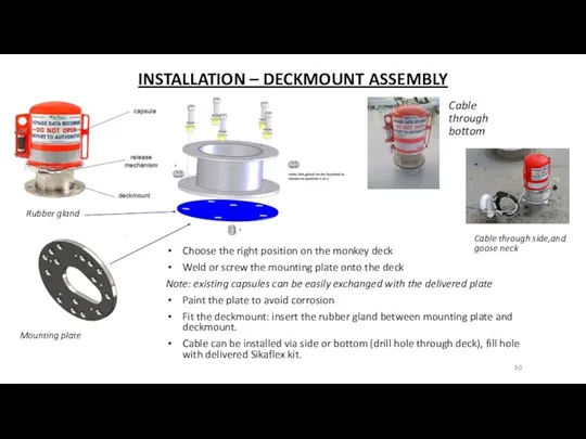
INSTALLATION – DECKMOUNT ASSEMBLY
Mounting plate
Choose the right position on the
INSTALLATION – DECKMOUNT ASSEMBLY
Mounting plate
Choose the right position on the
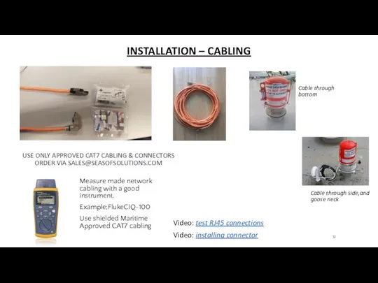
INSTALLATION – CABLING
Cable through bottom
Cable through side,and goose neck
USE ONLY
INSTALLATION – CABLING
Cable through bottom
Cable through side,and goose neck
USE ONLY
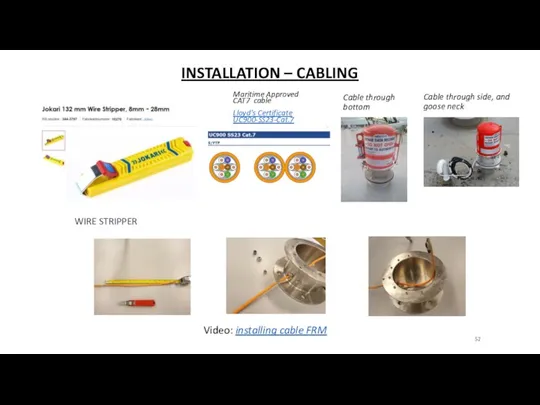
INSTALLATION – CABLING
Cable through bottom
Cable through side, and goose neck
WIRE
INSTALLATION – CABLING
Cable through bottom
Cable through side, and goose neck
WIRE
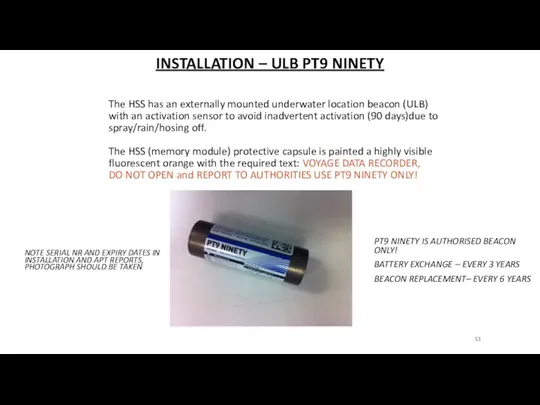
INSTALLATION – ULB PT9 NINETY
The HSS has an externally mounted
INSTALLATION – ULB PT9 NINETY
The HSS has an externally mounted
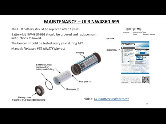
MAINTENANCE – ULB NW4860-695
The ULB battery should be replaced after
MAINTENANCE – ULB NW4860-695
The ULB battery should be replaced after
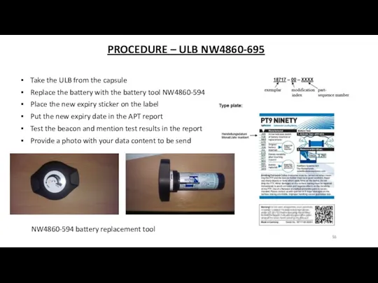
PROCEDURE – ULB NW4860-695
Take the ULB from the capsule
Replace the
PROCEDURE – ULB NW4860-695
Take the ULB from the capsule
Replace the

QUESTIONS?
QUESTIONS?
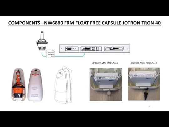
COMPONENTS –NW6880 FRM FLOAT FREE CAPSULE JOTRON TRON 40
Bracket MKI
COMPONENTS –NW6880 FRM FLOAT FREE CAPSULE JOTRON TRON 40
Bracket MKI
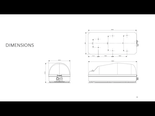
DIMENSIONS
DIMENSIONS
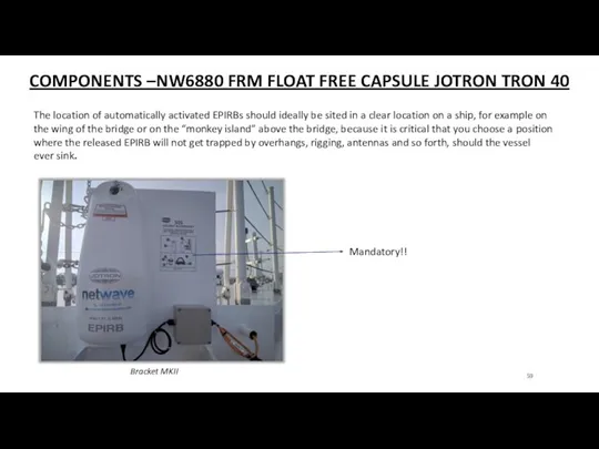
COMPONENTS –NW6880 FRM FLOAT FREE CAPSULE JOTRON TRON 40
The location of
COMPONENTS –NW6880 FRM FLOAT FREE CAPSULE JOTRON TRON 40
The location of
INSTALLATION –NW6880 FRM FLOAT FREE CAPSULE JOTRON TRON 40
- It is
INSTALLATION –NW6880 FRM FLOAT FREE CAPSULE JOTRON TRON 40
- It is
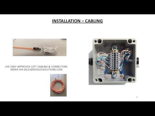
INSTALLATION – CABLING
USE ONLY APPROVED CAT7 CABLING & CONNECTORS
ORDER VIA
INSTALLATION – CABLING
USE ONLY APPROVED CAT7 CABLING & CONNECTORS
ORDER VIA
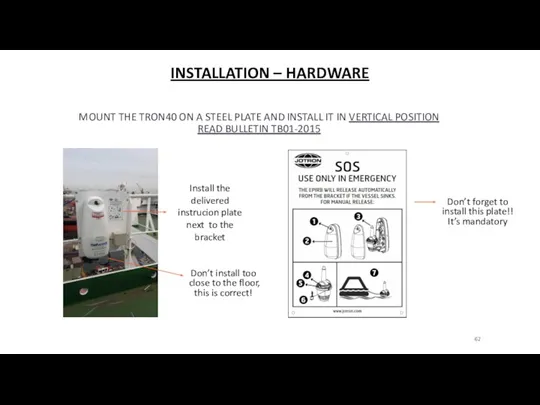
INSTALLATION – HARDWARE
MOUNT THE TRON40 ON A STEEL PLATE AND
INSTALLATION – HARDWARE
MOUNT THE TRON40 ON A STEEL PLATE AND
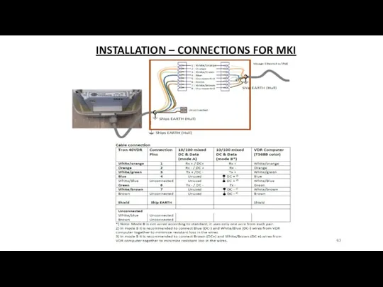
INSTALLATION – CONNECTIONS FOR MKI
INSTALLATION – CONNECTIONS FOR MKI
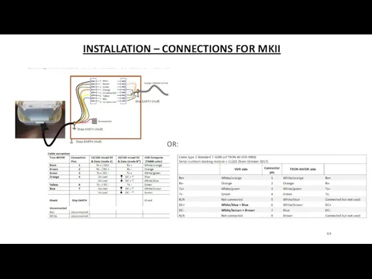
INSTALLATION – CONNECTIONS FOR MKII
OR:
INSTALLATION – CONNECTIONS FOR MKII
OR:
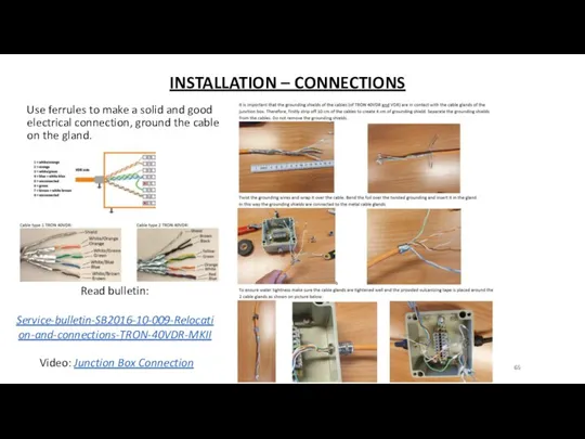
INSTALLATION – CONNECTIONS
Use ferrules to make a solid and good
INSTALLATION – CONNECTIONS
Use ferrules to make a solid and good

INSTALLATION – LOCATION
The location of automatically activated EPIRBs should ideally be
INSTALLATION – LOCATION
The location of automatically activated EPIRBs should ideally be
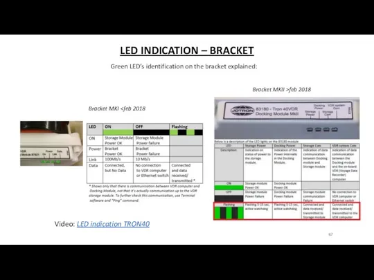
LED INDICATION – BRACKET
Green LED’s identification on the bracket explained:
Bracket MKI
LED INDICATION – BRACKET
Green LED’s identification on the bracket explained:
Bracket MKI

QUESTIONS?
QUESTIONS?
COMPONENTS – VHF INTERFACE NW6060
The audio-interface serves two combined functions;
1.
COMPONENTS – VHF INTERFACE NW6060
The audio-interface serves two combined functions;
1.
CONNECTIONS – VHF INTERFACE NW6060
Digital mic’s NW6020/6021 used < august 2020
Systems
CONNECTIONS – VHF INTERFACE NW6060
Digital mic’s NW6020/6021 used < august 2020
Systems
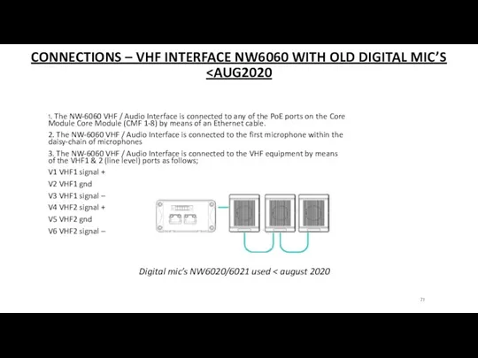
CONNECTIONS – VHF INTERFACE NW6060 WITH OLD DIGITAL MIC’S 1. The
CONNECTIONS – VHF INTERFACE NW6060 WITH OLD DIGITAL MIC’S
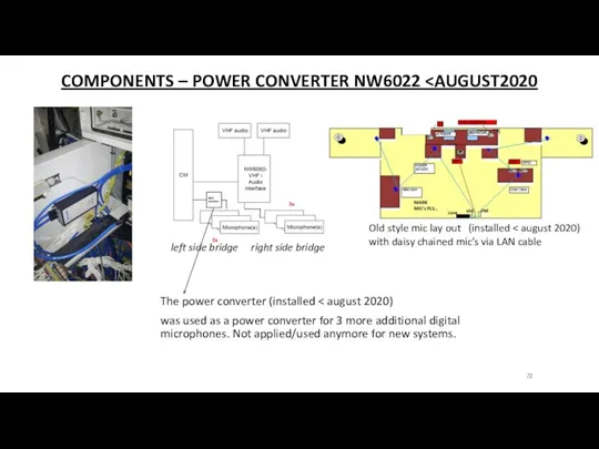
COMPONENTS – POWER CONVERTER NW6022 The power converter (installed < august
COMPONENTS – POWER CONVERTER NW6022
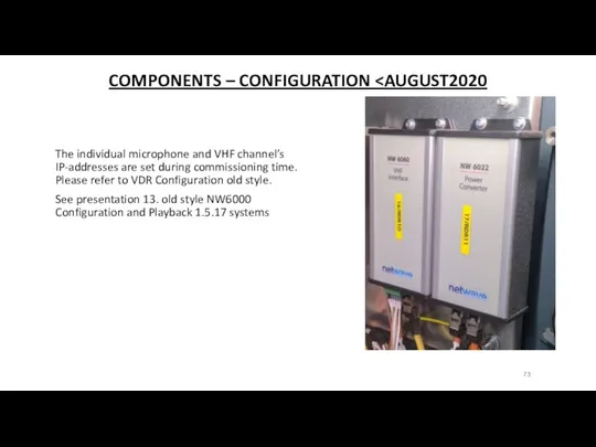
COMPONENTS – CONFIGURATION The individual microphone and VHF channel’s IP-addresses
COMPONENTS – CONFIGURATION
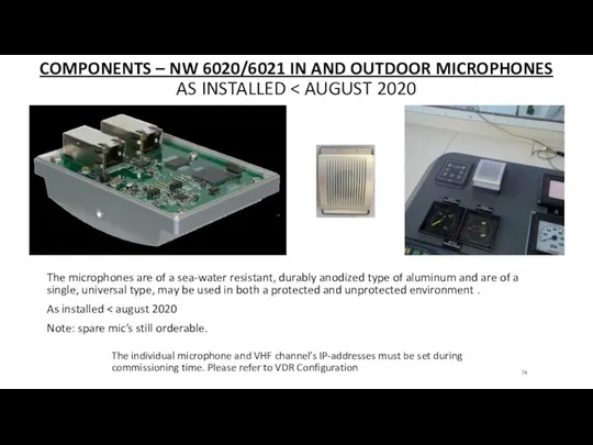
COMPONENTS – NW 6020/6021 IN AND OUTDOOR MICROPHONES
AS INSTALLED < AUGUST
COMPONENTS – NW 6020/6021 IN AND OUTDOOR MICROPHONES AS INSTALLED < AUGUST
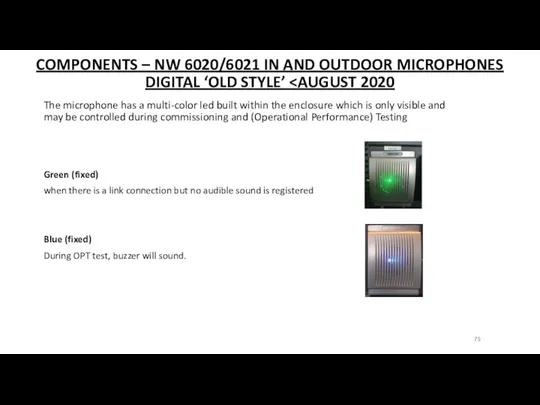
COMPONENTS – NW 6020/6021 IN AND OUTDOOR MICROPHONES DIGITAL ‘OLD STYLE’
COMPONENTS – NW 6020/6021 IN AND OUTDOOR MICROPHONES DIGITAL ‘OLD STYLE’
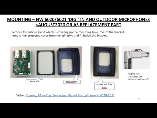
MOUNTING – NW 6020/6021 ‘DIGI’ IN AND OUTDOOR MICROPHONES
MOUNTING – NW 6020/6021 ‘DIGI’ IN AND OUTDOOR MICROPHONES
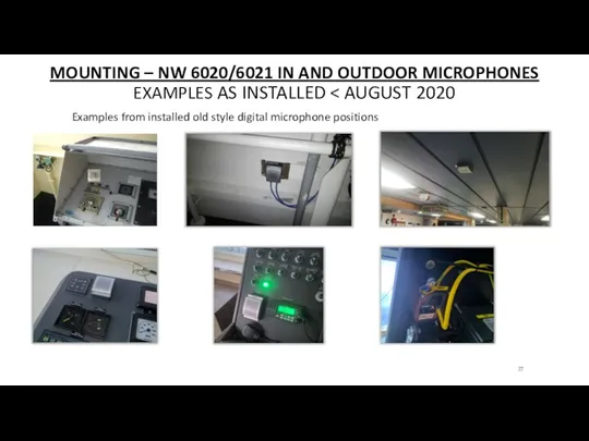
MOUNTING – NW 6020/6021 IN AND OUTDOOR MICROPHONES
EXAMPLES AS INSTALLED <
MOUNTING – NW 6020/6021 IN AND OUTDOOR MICROPHONES EXAMPLES AS INSTALLED <

QUESTIONS?
QUESTIONS?
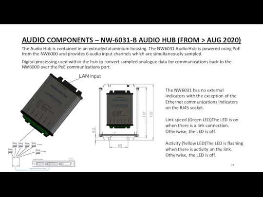
AUDIO COMPONENTS – NW-6031-B AUDIO HUB (FROM > AUG 2020)
The Audio Hub is
AUDIO COMPONENTS – NW-6031-B AUDIO HUB (FROM > AUG 2020)
The Audio Hub is
COMPONENTS – NW-6031-B AUDIO HUB (FROM > AUG 2020)
EXAMPLE INSTALLATION WITH
COMPONENTS – NW-6031-B AUDIO HUB (FROM > AUG 2020)
EXAMPLE INSTALLATION WITH
COMPONENTS – NW-6030-B ANALOGUE MICROPHONES FROM AUG 2020 >
The analogue microphones are of
COMPONENTS – NW-6030-B ANALOGUE MICROPHONES FROM AUG 2020 >
The analogue microphones are of
DIMENSIONS
Surface mounted
Flush mounted
DIMENSIONS
Surface mounted
Flush mounted
COMPONENTS – NW-6030-B ANALOGUE MICROPHONES FROM AUG 2020 >
Omnidirectional cover range
COMPONENTS – NW-6030-B ANALOGUE MICROPHONES FROM AUG 2020 >
Omnidirectional cover range
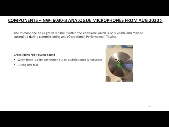
The microphone has a green led built within the enclosure which
The microphone has a green led built within the enclosure which
CONNECTIONS – NW- 6030-B ANALOGUE MICROPHONES
Audio-cabling from HUB to Mic should
CONNECTIONS – NW- 6030-B ANALOGUE MICROPHONES
Audio-cabling from HUB to Mic should
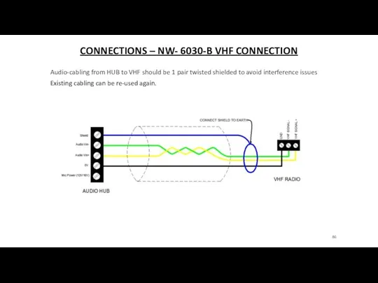
CONNECTIONS – NW- 6030-B VHF CONNECTION
Audio-cabling from HUB to VHF should
CONNECTIONS – NW- 6030-B VHF CONNECTION
Audio-cabling from HUB to VHF should
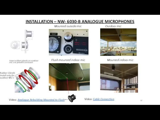
INSTALLATION – NW- 6030-B ANALOGUE MICROPHONES
Mounted outside mic Outdoor mic
INSTALLATION – NW- 6030-B ANALOGUE MICROPHONES
Mounted outside mic Outdoor mic

QUESTIONS?
QUESTIONS?
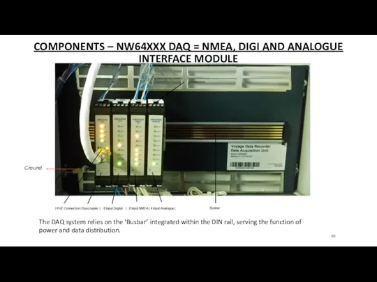
COMPONENTS – NW64XXX DAQ = NMEA, DIGI AND ANALOGUE INTERFACE MODULE
The
COMPONENTS – NW64XXX DAQ = NMEA, DIGI AND ANALOGUE INTERFACE MODULE
The
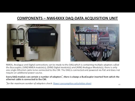
COMPONENTS – NW64XXX DAQ-DATA ACQUISITION UNIT
NMEA, Analogue and Digital connections can
COMPONENTS – NW64XXX DAQ-DATA ACQUISITION UNIT
NMEA, Analogue and Digital connections can
COMPONENTS - NW-6410 WAVENET BUSCOUPLER
There must always be 1 BusCoupler
COMPONENTS - NW-6410 WAVENET BUSCOUPLER
There must always be 1 BusCoupler
COMPONENTS - NW-6410 WAVENET BUSCOUPLER
The DAQ Module can be set
COMPONENTS - NW-6410 WAVENET BUSCOUPLER
The DAQ Module can be set
INSTALLATION - NW-6410 WAVENET BUSCOUPLER
This adaptor has following ports;
Ethernet
INSTALLATION - NW-6410 WAVENET BUSCOUPLER
This adaptor has following ports;
Ethernet
INSTALLATION - NW-64XXX CONNECTOR AND WIRING
IDENTIFICATION IS AS FOLLOWS
Please
INSTALLATION - NW-64XXX CONNECTOR AND WIRING
IDENTIFICATION IS AS FOLLOWS
Please
INSTALLATION - NW-64XXX CONNECTOR AND WIRING
IDENTIFICATION IS AS FOLLOWS
Please
INSTALLATION - NW-64XXX CONNECTOR AND WIRING
IDENTIFICATION IS AS FOLLOWS
Please
INSTALLATION - NW-64XXX INPUT CHANNEL NUMBERING
Please note:
LED’s from each individual
INSTALLATION - NW-64XXX INPUT CHANNEL NUMBERING
Please note:
LED’s from each individual
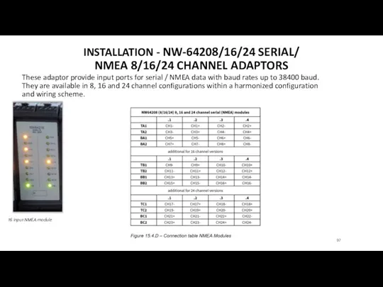
INSTALLATION - NW-64208/16/24 SERIAL/
NMEA 8/16/24 CHANNEL ADAPTORS
These adaptor provide input
INSTALLATION - NW-64208/16/24 SERIAL/
NMEA 8/16/24 CHANNEL ADAPTORS
These adaptor provide input
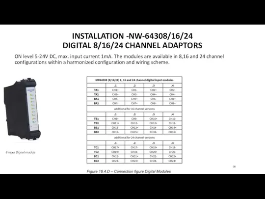
INSTALLATION -NW-64308/16/24
DIGITAL 8/16/24 CHANNEL ADAPTORS
ON level 5-24V DC, max.
INSTALLATION -NW-64308/16/24
DIGITAL 8/16/24 CHANNEL ADAPTORS
ON level 5-24V DC, max.
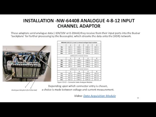
INSTALLATION -NW-64408 ANALOGUE 4-8-12 INPUT CHANNEL ADAPTOR
These adaptors send analogue
INSTALLATION -NW-64408 ANALOGUE 4-8-12 INPUT CHANNEL ADAPTOR
These adaptors send analogue

QUESTIONS?
QUESTIONS?
COMPONENTS – NW6044 VIDEO INTERFACE
X-band, S-band and ECDIS video should be
COMPONENTS – NW6044 VIDEO INTERFACE
X-band, S-band and ECDIS video should be
COMPONENTS – NW6044 VIDEO INTERFACE
Type of Video Channels
Capture RGB, RGBHV, Monochrome
COMPONENTS – NW6044 VIDEO INTERFACE
Type of Video Channels
Capture RGB, RGBHV, Monochrome
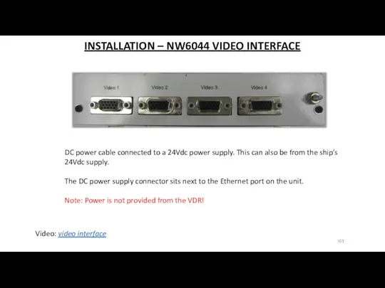
INSTALLATION – NW6044 VIDEO INTERFACE
Video: video interface
DC power cable connected to
INSTALLATION – NW6044 VIDEO INTERFACE
Video: video interface
DC power cable connected to

QUESTIONS?
QUESTIONS?
 Microcontrollers misis 2017. Applications
 Международная журналистика
 Электронные ресурсы для подготовки к Всероссийской олимпиаде школьников по русскому языку и литературе
 Инженерия программного обеспечения. Введение (модуль 1)
 SMM-маркетинг в социальных сетях
 ООП на Delphi – 10: Базы данных на Delphi
 Руководства пользователя ППО СУФД
 Описание ситуаций, возникающих при работе с приложением
 Урок по теме Сортировка, удаление и добавление записей 8 класс
 Паскаль АВС. Часть 3. Арифметические операции.
 Информация. Виды информации. Свойства информации
 Электронная почта (5 класс)
 Высокие учебные результаты обучения при их активной динамике за последние 3 года
 Кодирование информации
 Основные устройства персонального компьютера
 Деревья. Формальное определение дерева
 ВКР: Разработка мобильной игры жанра платформер-головоломка
 Agile – новый подход к управлению проектами
 Веб 2.0 у школі
 Связь web-страницы с базой данных
 Аватария - мир, где сбываются мечты. Часть 1. Объяснение игры
 Большой информационный турнир
 Внешние устройства компьютера
 Технологический слой
 Роль журналиста в обществе
 О конкурсе EUROBOT 2018. Причина выбора робототехники
 Обзор функциональных возможностей ERP–решения фирмы 1С
 История языков программирования