- Network Infrastructure

Содержание
- 30. Ring Topology In a ring topology, the output of one node is the input of the
- 31. Advantages of Ring Topology: This type of network topology is very organized. Each node gets to
- 32. Disadvantages of Ring Topology: Each packet of data must pass through all the computers between source
- 33. Mesh Topology In a full mesh, each node in the network is connected to every other
- 34. Partial Mesh The best known example of a mesh network is the Internet with its innumerable
- 35. Advantages of Mesh Topology: Data can be transmitted from different devices simultaneously. This topology can withstand
- 36. Disadvantages of Mesh Topology: There are high chances of redundancy in many of the network connections.
- 37. You should protect the physical network to prevent unauthorized persons from tapping into the network cable
- 38. Wired network topologies Star Topology Bus Topology Ring Topology Mesh Topology Wired network security overview Summary
- 39. Network Infrastructure 3. Compare and contrast common wireless network configurations
- 40. Wi-Fi Hotspots Wireless computer networks have now become commonplace. They are popular in many office environments,
- 41. Ease of deployment Equipment requirements are minimal, and there is typically no need to run cable.
- 42. There are two basic configuration options supported for wireless networks: Ad‐hoc mode Infrastructure mode Wireless network
- 43. Ad Hoc Mode An ad‐hoc network is limited to no more than nine client devices. Two
- 44. Ad Hoc Mode To set up an ad-hoc wireless network, each wireless adapter must be configured
- 45. Infrastructure Mode The default configuration for most wireless adapters is to support infrastructure mode only. In
- 46. Infrastructure Mode You can also connect the AP to your wired network to give wireless clients
- 47. Extended service set (ESS)
- 48. Extended service set definition An extended service set (ESS) is a set of one or more
- 49. SSID use Each BSS or ESS is identified by a Service set identifier (SSID) - a
- 50. MSM460 Front View The Access Point will have one or more internal radios. Each radio can
- 51. MSM460 Back View The AP will have at least one wired Ethernet port, enabling you to
- 52. HP MSM466-R For some applications, deploying one or more APs outside may be necessary. The HP
- 53. Using AP One important consideration is the placement of your AP. You want to place the
- 54. Using AP You must consider two basic issues when determining how many Aps you need. One
- 55. Broadcast Range Traditionally, security has been one of the weak areas for wireless networking. If it
- 56. Reduce Broadcast Power Most APs let you configure the radio’s signal strength. By reducing the signal
- 57. Hybrid Network Many networks are best described as hybrid networks, bringing together different topologies and even
- 58. Wireless network justifications Wireless network configurations Ad-hoc and infrastructure modes The use of hybrid networks Summary
- 59. Network Infrastructure 4. Determine Wireless Distribution Service (WDS)
- 60. Wireless distribution system (WDS) As a wireless network expands and additional APs are required, it is
- 61. WDS Requirements Basic requirements when configuring APs for WDS include: Radio channel Each AP’s radio(s) must
- 62. WDS Examples When setting up WDS, you can configure an AP to operate in a wireless
- 63. Simple WDS Example The AP connected to the switch is operating in wireless bridging mode and
- 64. WDS Multipoint Connection You can also configure a multipoint connection that has one main station and
- 65. WDS Relay Configuration You can use WDS even if the remote base stations are not in
- 66. WDS Point-to-Point Bridge As one final example, we take a look at using wireless bridging to
- 67. MSM760 Controller When deploying an HP AP, you will need to configure the management mode. The
- 68. MSM760 Controller When configured for controlled mode, the AP will attempt to locate a controller by
- 69. Network Infrastructure 5. Compare wireless network security options
- 70. Wireless Security Overview Security options MAC address filtering Wired Equivalent Privacy (WEP) Wi-Fi Protected Access (WPA)
- 71. Wireless Security - MAC address filtering MAC address filters are often used as an added wireless
- 72. Wireless Security - WEP In Open System authentication, the WLAN client need not provide its credentials
- 73. WEP. Shared Key authentication In Shared Key authentication, the WEP key is used for authentication in
- 74. Wireless Security - WPA Wi-Fi Protected Access (WPA) is a security protocols and security certification programs
- 75. TKIP uses the RC4 stream encryption algorithm as its basis. The new protocol, however, encrypts each
- 76. Advanced Encryption Standard (AES) The Advanced Encryption Standard (AES) specifies a FIPS-approved cryptographic algorithm that can
- 77. Versions of WPA2 There are two versions WPA2: WPA-Personal (WPA Pre Shared Key or WPA-PSK); WPA-Enterprise.
- 78. Potential problems wireless network security MAC address filtering Wired Equivalent Privacy (WEP) Wi-Fi Protected Access (WPA)
- 79. Network Infrastructure 6. Describe the purpose and use of key network technologies
- 80. We end this lecture with a brief discussion of some technologies and concepts that are central
- 81. Network Segmentation There are several reasons why you might consider segmenting a network, including: Optimizing network
- 82. Network Segmentation example In this example, segmentation accommodates the needs of two diverse work groups. Both
- 83. Firewall A firewall is a security device that can filter the traffic into or out of
- 84. Perimeter Network One specialized type of segmentation is a perimeter network (DMZ). A perimeter network is
- 85. Address translation is another important technology for when devices on an internal network need to access
- 86. Proxy Server One type of specialized server you might find in a perimeter network is a
- 87. Virtual Private Network (VPN) A VPN is designed to provide a secure, reliable communication path over
- 89. Скачать презентацию
 Информация и ее виды
 Урок по теме: Действия объекта
 Разработка программного обеспечения
 Особливості мови програмування Java (лекція 1)
 Актуальные проблемы архивного дела. Автоматизированная Система хранения электронных документов Айтеко
 Структура ГИС (данные)
 Макетирование страниц CSS - фреймворки - Twitter Bootstrap
 Инструменты и методы разработки веб-сайтов
 Многомерные массивы. Лекция 7
 Современные системы управления взаимоотношений с клиентами
 Программирование на языке Паскаль. (§ 54 - § 61)
 Структура и принципы построения сети интернет
 Устав команды поддержки
 Модульдік тестілеу
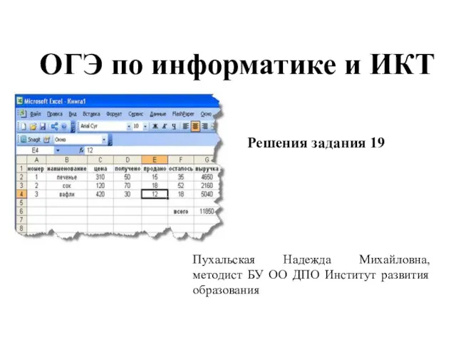 ОГЭ по информатике и ИКТ. Задание 19
 Представление чисел в памяти компьютера. 9 класс
 Интегрированный урок информатика+физика Моделирование как метод познания
 Разработка проекта сети для предприятия с введением дополнительного сегмента
 Программирование циклов с заданным условием окончания работы
 Обеспечение целостности БД
 Создание гипертекстового документа
 IP-Телефония в NGN
 173769ce-3618-4d16-803d-67b69f2e668a
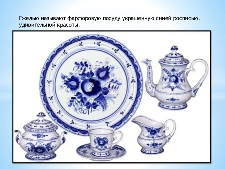 Презентация Ознакомления детей с гжелью
 Технологии хранения информации и больших объемов данных. Лекция 1
 Алгоритмы. Этапы решения задач
 Кодування інформації
 Programming logic and design seventh edition. Chapter 5. Looping