- Robertson's multiplication

Содержание
- 2. 2’s Complement Theory Binary representation of integers Capable of representing both positive and negative integers An
- 3. Binary Addition and Overflow Overflow occurs when the addition result is too large to fit in
- 4. Overflow Examples 0101 (5)10 - 1101 (-3)10 1000 (-8)10 0101 (5)10 - 1101 (-3)10 0 1000
- 5. How to Correct Overflow? In this lab, you will explore several possibilities to develop a solution
- 6. 2’s Complement Robertson’s Multiplication Basic Idea Accumulate a partial sum in multiple steps. The rightmost bit
- 7. Multiplication Example 10102 * 11002 0000 1100 1010 0000 0110 1010 0000 0011 1010 1010 0011
- 8. Overall Guidelines: Glue Logic Use D Flip Flop En wo/SQ/ Provided The most significant bit of
- 9. Implementation Summary
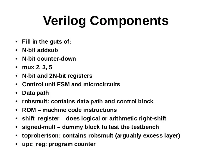
- 10. Verilog Components Fill in the guts of: N-bit addsub N-bit counter-down mux 2, 3, 5 N-bit
- 12. Скачать презентацию
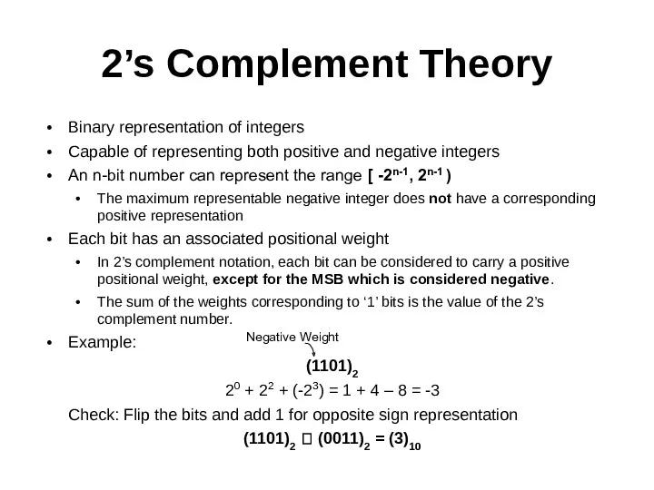
2’s Complement Theory
Binary representation of integers
Capable of representing both positive and
2’s Complement Theory
Binary representation of integers
Capable of representing both positive and
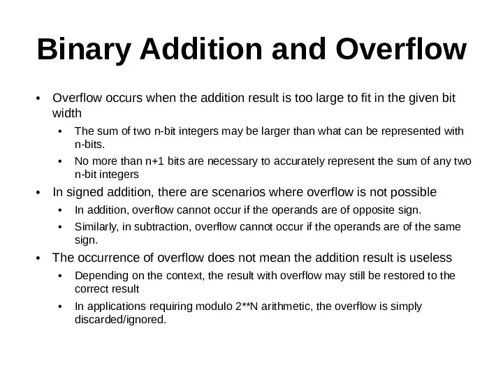
Binary Addition and Overflow
Overflow occurs when the addition result is too
Binary Addition and Overflow
Overflow occurs when the addition result is too
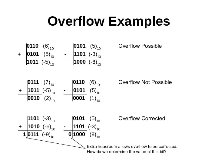
Overflow Examples
0101 (5)10
- 1101 (-3)10
1000 (-8)10
0101 (5)10
- 1101
Overflow Examples
0101 (5)10
- 1101 (-3)10
1000 (-8)10
0101 (5)10
- 1101
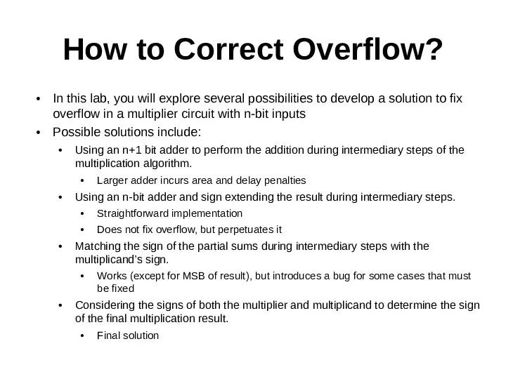
How to Correct Overflow?
In this lab, you will explore several possibilities
How to Correct Overflow?
In this lab, you will explore several possibilities
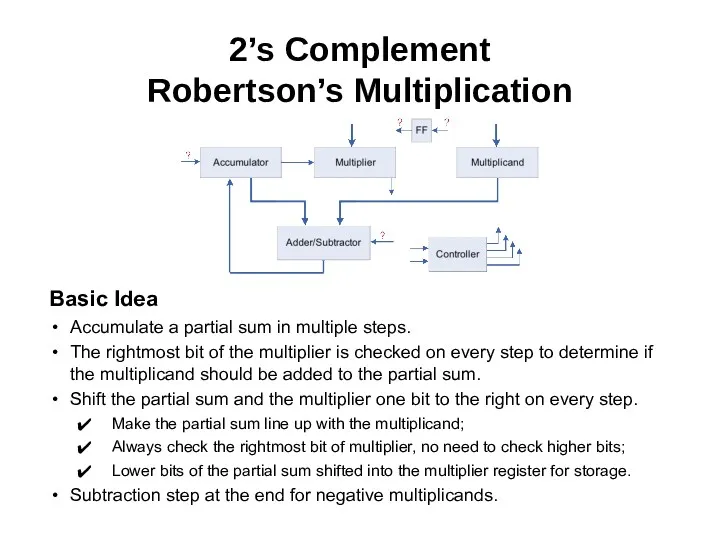
2’s Complement
Robertson’s Multiplication
Basic Idea
Accumulate a partial sum in multiple steps.
The rightmost
2’s Complement
Robertson’s Multiplication
Basic Idea
Accumulate a partial sum in multiple steps.
The rightmost
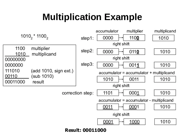
Multiplication Example
10102 * 11002
0000
1100
1010
0000
0110
1010
0000
0011
1010
1010
0011
1010
1101
0001
1010
step2:
step1:
right shift
right shift
accumulator
multiplier
multiplicand
accumulator = accumulator + multiplicand
right
Multiplication Example
10102 * 11002
0000
1100
1010
0000
0110
1010
0000
0011
1010
1010
0011
1010
1101
0001
1010
step2:
step1:
right shift
right shift
accumulator
multiplier
multiplicand
accumulator = accumulator + multiplicand
right
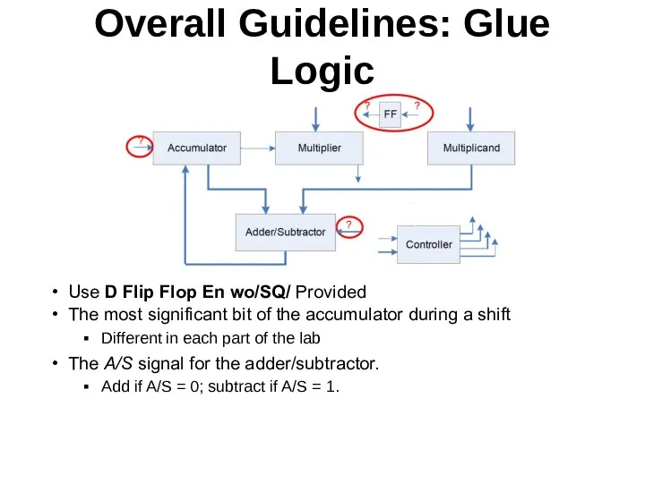
Overall Guidelines: Glue Logic
Use D Flip Flop En wo/SQ/ Provided
The most
Overall Guidelines: Glue Logic
Use D Flip Flop En wo/SQ/ Provided
The most
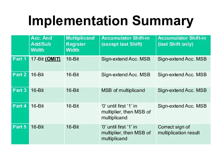
Implementation Summary
Implementation Summary
Verilog Components
Fill in the guts of:
N-bit addsub
N-bit counter-down
mux 2,
Verilog Components
Fill in the guts of:
N-bit addsub
N-bit counter-down
mux 2,
 Подходы к понятию информации и измерению информации. Информационные объекты различных видов
 Требования к оформлению презентации
 Этапы проектирования базы данных
 Строки
 Основы языка СИ. Часть 2. Оператор IF-ELSE, SWITCH. Циклы. GOTO
 Қоғам дамуының шешуші секторларында АКТ-дың рөлі.АКТ-дың стандарттары
 Перевод целых чисел в различные системы счисления
 Услуга Интегрум Компании
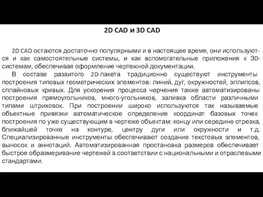 2D CAD и 3D CAD
 Программирование в компьютерных системах
 Знакомство с Adobe Illustrator
 Целостность данных
 Цикл с параметром (цикл с заданным числом повторений, цикл-ДЛЯ)
 Веб-сервер Apache Tomcat 6
 Your First Android Project!
 Погодный бот
 Урок по информатике Практические возможности графического редактора
 Виды компьютерных сетей
 Операционные системы. Часть 1. Определение
 Разработка предложений по идентификации пользователей при обеспечении защиты информации в компании Мосинжпроект
 Алгоритмы в сказках
 Оформление библиографического списка. Примеры библиографических записей ГОСТ 7.0.100-2018 Библиографическая запись
 Систематический каталог
 Шаблон презентации Новогодний
 Место информационной безопасности в системе национальной безопасности России
 Механизмы ввода и вывода информации. Понятие сериализации
 Введение в программную инженерию. Жизненный цикл программных средств, ч. 1
 Проектный процесс в дизайне рекламы. Проектирование товарного знака (знака обслуживания) и фирменного стиля