- Routing concepts

Содержание
- 2. This PowerPoint deck is divided in two parts: Instructor Planning Guide Information to help you become
- 3. Chapter 1: Routing Concepts Routing and Switching Essentials 6.0 Planning Guide
- 4. What activities are associated with this chapter? Chapter 1: Activities The password used in the Packet
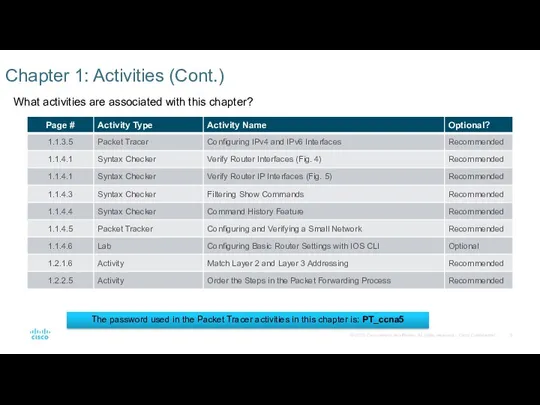
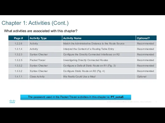
- 5. What activities are associated with this chapter? Chapter 1: Activities (Cont.) The password used in the
- 6. What activities are associated with this chapter? Chapter 1: Activities (Cont.) The password used in the
- 7. Students should complete Chapter 1, “Assessment” after completing Chapter 1. Quizzes, labs, Packet Tracers and other
- 8. Prior to teaching Chapter 1, the instructor should: Complete Chapter 1, “Assessment.” The objectives of this
- 9. 1.1.2.7 Explain that the default-gateway command on the switch is used for management purposes such as
- 10. 1.3.1.2 – Discuss the show ip route codes for the most popular routing protocols: R –
- 11. For additional help with teaching strategies, including lesson plans, analogies for difficult concepts, and discussion topics,
- 13. Chapter 1: Routing Concepts CCNA Routing and Switching Routing and Switching Essentials v6.0
- 14. 1.1 Router Initial Configuration Configure a router to route between multiple directly-connected networks. Describe the primary
- 15. 1.3 Router Operation Explain how a router learns about remote networks when operating in a small
- 16. 1.1 Router Initial Configuration
- 17. Router Functions Characteristics of a Network Networks are relied on for web applications, IP telephony, video
- 18. Router Functions Characteristics of a Network (Cont.) Cost – general expense for purchasing of network components
- 19. Router Functions Why Routing? Router: Connects one network to another network Determines the best route to
- 20. Router Functions Routers Are Computers A router is a specialized computer and requires the same components
- 21. Router Functions Routers Are Computers (Cont.)
- 22. Router Functions Routers Interconnect Networks Router is responsible for forwarding packets from network to network, from
- 23. Router Functions Routers Choose Best Paths The primary functions of a router are to: Determine the
- 24. Router Functions Packet Forwarding Mechanisms Routers support three packet-forwarding mechanisms: Process switching – Slower and older
- 25. Router Functions Packet Forwarding Mechanisms (Cont.) Cisco Express Forwarding – CEF Fastest, most recent, and preferred
- 26. Router Functions Packet Tracer – Using Traceroute to Discover the Network
- 27. Router Functions Lab – Mapping the Internet
- 28. Connect Devices Connect to a Network Home Office devices might connect as follows: Laptops and tablets
- 29. Connect Devices Connect to a Network (Cont.) Branch site devices might connect as follows: Desktop PCs,
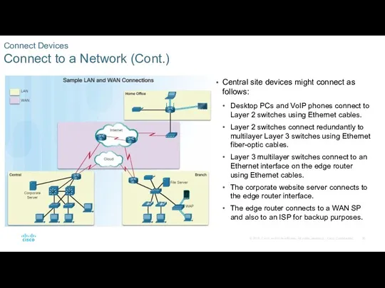
- 30. Connect Devices Connect to a Network (Cont.) Central site devices might connect as follows: Desktop PCs
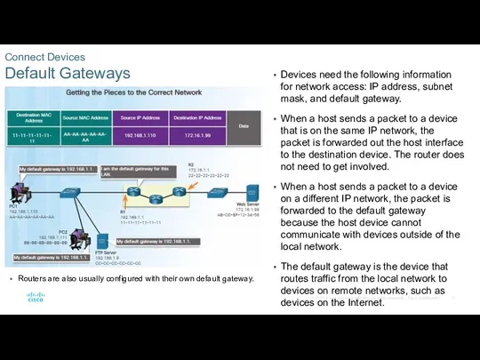
- 31. Connect Devices Default Gateways Devices need the following information for network access: IP address, subnet mask,
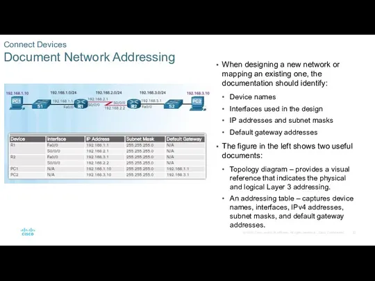
- 32. Connect Devices Document Network Addressing When designing a new network or mapping an existing one, the
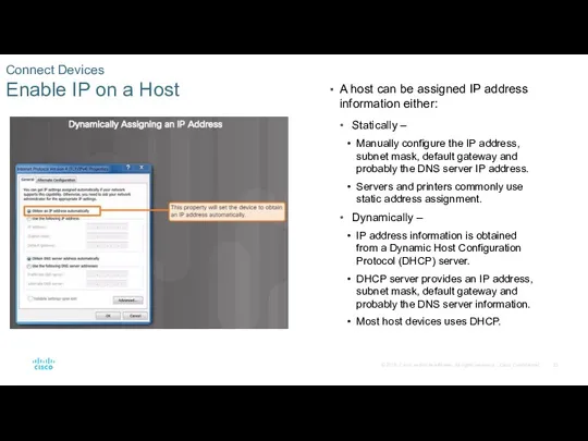
- 33. Connect Devices Enable IP on a Host A host can be assigned IP address information either:
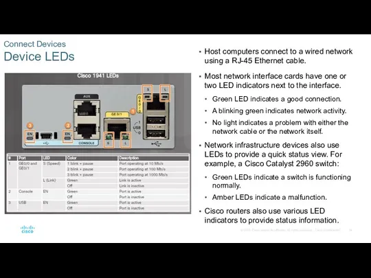
- 34. Connect Devices Device LEDs Host computers connect to a wired network using a RJ-45 Ethernet cable.
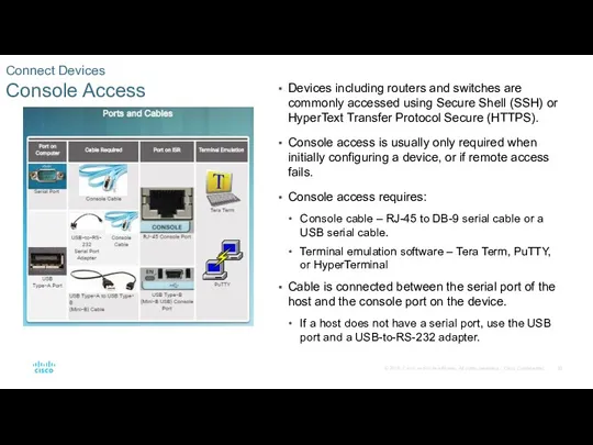
- 35. Connect Devices Console Access Devices including routers and switches are commonly accessed using Secure Shell (SSH)
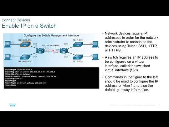
- 36. Connect Devices Enable IP on a Switch Network devices require IP addresses in order for the
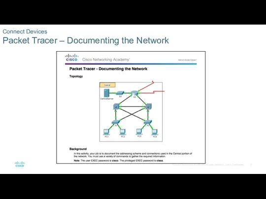
- 37. Connect Devices Packet Tracer – Documenting the Network
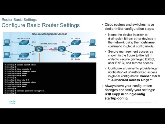
- 38. Router Basic Settings Configure Basic Router Settings Cisco routers and switches have similar initial configuration steps:
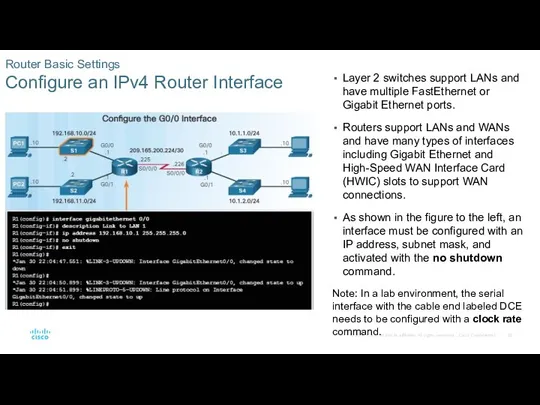
- 39. Router Basic Settings Configure an IPv4 Router Interface Layer 2 switches support LANs and have multiple
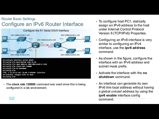
- 40. Router Basic Settings Configure an IPv6 Router Interface To configure host PC1, statically assign an IPv6
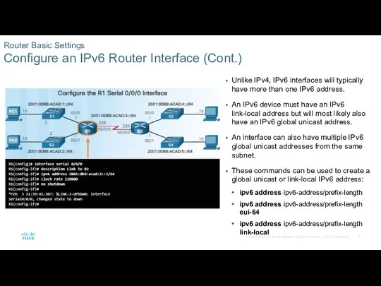
- 41. Router Basic Settings Configure an IPv6 Router Interface (Cont.) Unlike IPv4, IPv6 interfaces will typically have
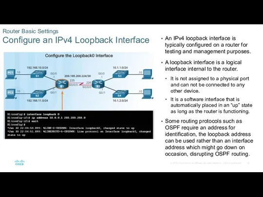
- 42. Router Basic Settings Configure an IPv4 Loopback Interface An IPv4 loopback interface is typically configured on
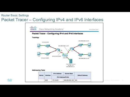
- 43. Router Basic Settings Packet Tracer – Configuring IPv4 and IPv6 Interfaces
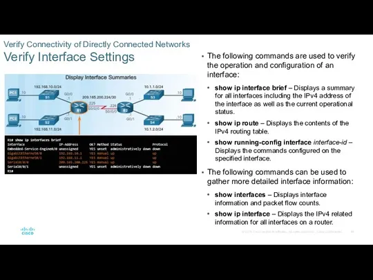
- 44. Verify Connectivity of Directly Connected Networks Verify Interface Settings The following commands are used to verify
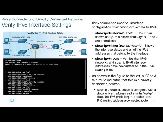
- 45. Verify Connectivity of Directly Connected Networks Verify IPv6 Interface Settings IPv6 commands used for interface configuration
- 46. Verify Connectivity of Directly Connected Networks Filter Show Command Output Commands that generate multiple screens of
- 47. Verify Connectivity of Directly Connected Networks Command History Feature The command history feature shows previously executed
- 48. Verify Connectivity of Directly Connected Networks Packet Tracer – Configuring and Verifying a Small Network
- 49. Verify Connectivity of Directly Connected Networks Lab – Configuring Basic Router Settings with IOS CLI
- 50. 1.2 Routing Decisions
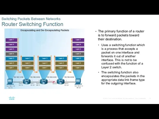
- 51. Switching Packets Between Networks Router Switching Function The primary function of a router is to forward
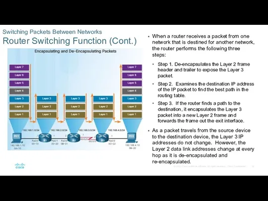
- 52. Switching Packets Between Networks Router Switching Function (Cont.) When a router receives a packet from one
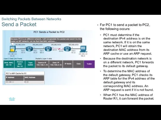
- 53. Switching Packets Between Networks Send a Packet For PC1 to send a packet to PC2, the
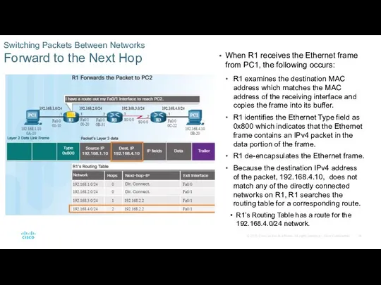
- 54. Switching Packets Between Networks Forward to the Next Hop When R1 receives the Ethernet frame from
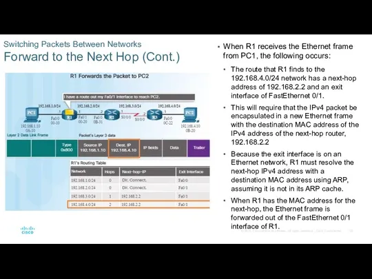
- 55. Switching Packets Between Networks Forward to the Next Hop (Cont.) When R1 receives the Ethernet frame
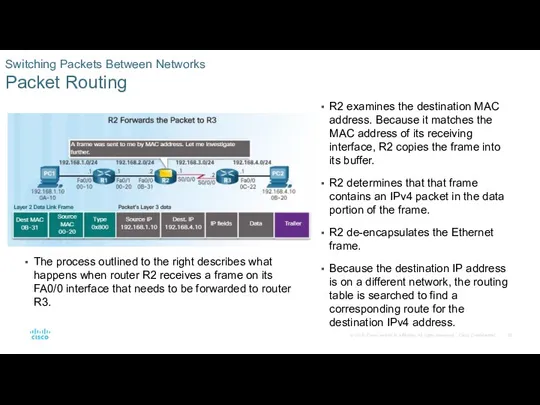
- 56. Switching Packets Between Networks Packet Routing R2 examines the destination MAC address. Because it matches the
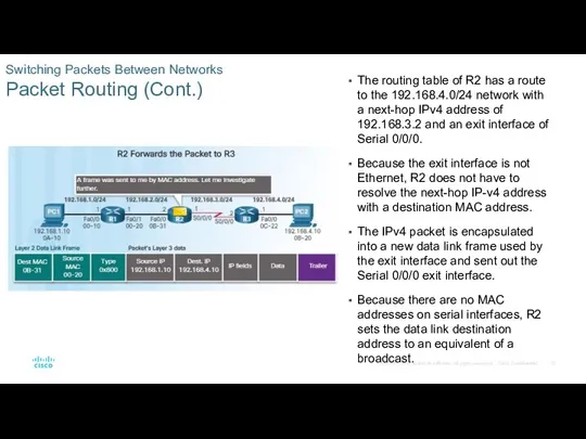
- 57. Switching Packets Between Networks Packet Routing (Cont.) The routing table of R2 has a route to
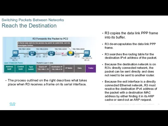
- 58. Switching Packets Between Networks Reach the Destination R3 copies the data link PPP frame into its
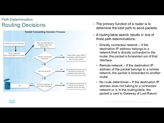
- 59. Path Determination Routing Decisions The primary function of a router is to determine the best path
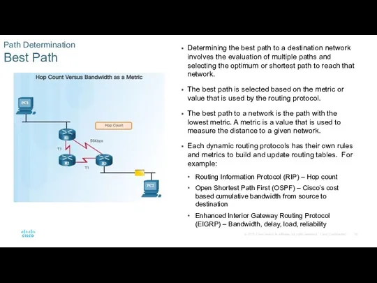
- 60. Path Determination Best Path Determining the best path to a destination network involves the evaluation of
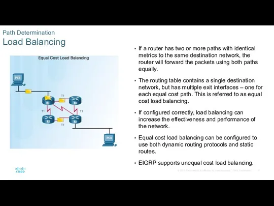
- 61. Path Determination Load Balancing If a router has two or more paths with identical metrics to
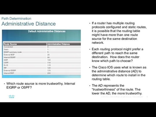
- 62. Path Determination Administrative Distance If a router has multiple routing protocols configured and static routes, it
- 63. 1.3 Router Operation
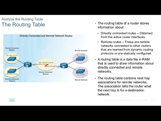
- 64. Analyze the Routing Table The Routing Table The routing table of a router stores information about:
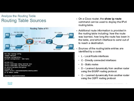
- 65. Analyze the Routing Table Routing Table Sources On a Cisco router, the show ip route command
- 66. Analyze the Routing Table Remote Network Routing Entries You must know how to interpret the content
- 67. Directly Connected Routes Directly Connected Interfaces A new router without any configured interfaces will have an
- 68. Directly Connected Routes Directly Connected Routing Table Entries With IOS version 15 and later, an active
- 69. Directly Connected Routes Directly Connected Examples When the interfaces are configured with an appropriate IP address,
- 70. Directly Connected Routes Directly Connected IPv6 Example The figure to the left shows the configuration steps
- 71. Directly Connected Routes Packet Tracer – Investigating Directly Connected Routes
- 72. Statically Learned Routes Static Routes After directly connected interfaces are configured and added to the routing
- 73. Statically Learned Routes Static Routes (Cont.) There are two main types of static routes in the
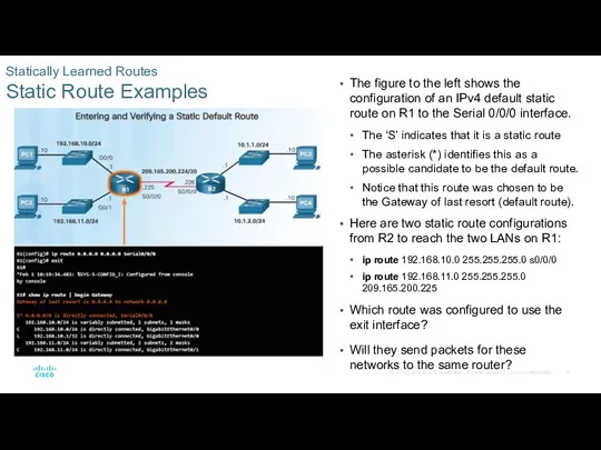
- 74. Statically Learned Routes Static Route Examples The figure to the left shows the configuration of an
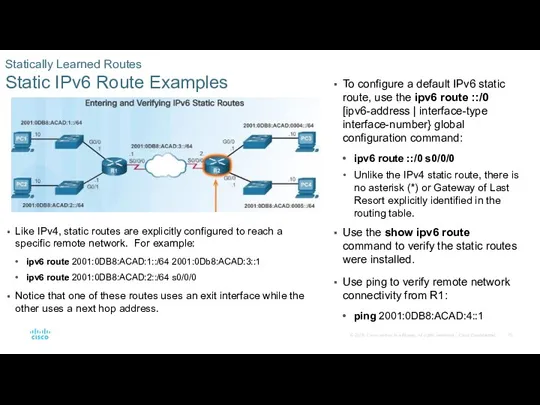
- 75. Statically Learned Routes Static IPv6 Route Examples To configure a default IPv6 static route, use the
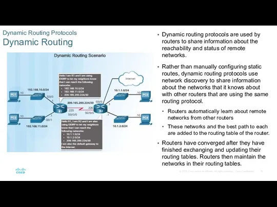
- 76. Dynamic Routing Protocols Dynamic Routing Dynamic routing protocols are used by routers to share information about
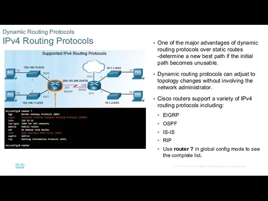
- 77. Dynamic Routing Protocols IPv4 Routing Protocols One of the major advantages of dynamic routing protocols over
- 78. 1.4 Summary
- 79. Configure a router to route between multiple directly connected networks. Explain how routers use information in
- 80. Chapter 1 New Terms and Commands
- 81. Chapter 1 New Terms and Commands (Cont.)
- 83. Скачать презентацию
This PowerPoint deck is divided in two parts:
Instructor Planning Guide
Information to
This PowerPoint deck is divided in two parts:
Instructor Planning Guide
Information to
Chapter 1: Routing Concepts
Routing and Switching Essentials 6.0 Planning Guide
Chapter 1: Routing Concepts
Routing and Switching Essentials 6.0 Planning Guide
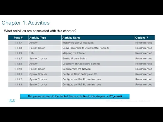
What activities are associated with this chapter?
Chapter 1: Activities
The password used
What activities are associated with this chapter?
Chapter 1: Activities
The password used
What activities are associated with this chapter?
Chapter 1: Activities (Cont.)
The password
What activities are associated with this chapter?
Chapter 1: Activities (Cont.)
The password
What activities are associated with this chapter?
Chapter 1: Activities (Cont.)
The password
What activities are associated with this chapter?
Chapter 1: Activities (Cont.)
The password
Students should complete Chapter 1, “Assessment” after completing Chapter 1.
Quizzes, labs,
Students should complete Chapter 1, “Assessment” after completing Chapter 1.
Quizzes, labs,
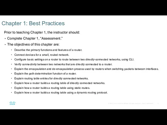
Prior to teaching Chapter 1, the instructor should:
Complete Chapter 1, “Assessment.”
The
Prior to teaching Chapter 1, the instructor should:
Complete Chapter 1, “Assessment.”
The
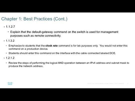
1.1.2.7
Explain that the default-gateway command on the switch is used for
1.1.2.7
Explain that the default-gateway command on the switch is used for
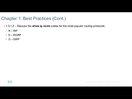
1.3.1.2 – Discuss the show ip route codes for the most
1.3.1.2 – Discuss the show ip route codes for the most
For additional help with teaching strategies, including lesson plans, analogies for
For additional help with teaching strategies, including lesson plans, analogies for
Chapter 1: Routing Concepts
CCNA Routing and Switching
Routing and Switching Essentials v6.0
Chapter 1: Routing Concepts
CCNA Routing and Switching
Routing and Switching Essentials v6.0
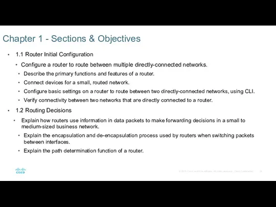
1.1 Router Initial Configuration
Configure a router to route between multiple directly-connected
1.1 Router Initial Configuration
Configure a router to route between multiple directly-connected
1.3 Router Operation
Explain how a router learns about remote networks when
1.3 Router Operation
Explain how a router learns about remote networks when
1.1 Router Initial Configuration
1.1 Router Initial Configuration
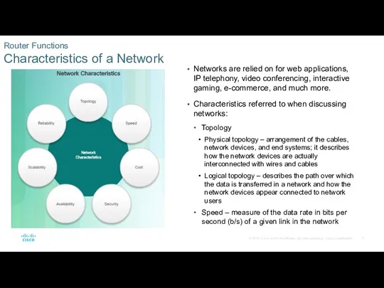
Router Functions
Characteristics of a Network
Networks are relied on for web applications,
Router Functions
Characteristics of a Network
Networks are relied on for web applications,
Router Functions
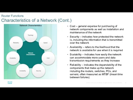
Characteristics of a Network (Cont.)
Cost – general expense for purchasing
Router Functions
Characteristics of a Network (Cont.)
Cost – general expense for purchasing
Router Functions
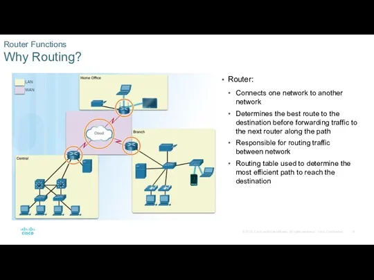
Why Routing?
Router:
Connects one network to another network
Determines the best
Router Functions
Why Routing?
Router:
Connects one network to another network
Determines the best
Router Functions
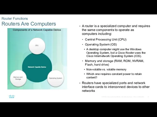
Routers Are Computers
A router is a specialized computer and requires
Router Functions
Routers Are Computers
A router is a specialized computer and requires
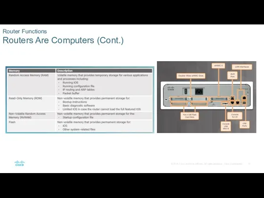
Router Functions
Routers Are Computers (Cont.)
Router Functions
Routers Are Computers (Cont.)
Router Functions
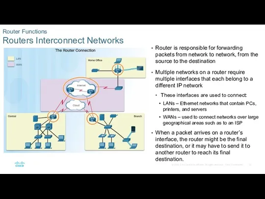
Routers Interconnect Networks
Router is responsible for forwarding packets from network
Router Functions
Routers Interconnect Networks
Router is responsible for forwarding packets from network
Router Functions
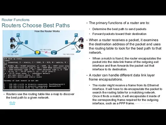
Routers Choose Best Paths
The primary functions of a router are
Router Functions
Routers Choose Best Paths
The primary functions of a router are
Router Functions
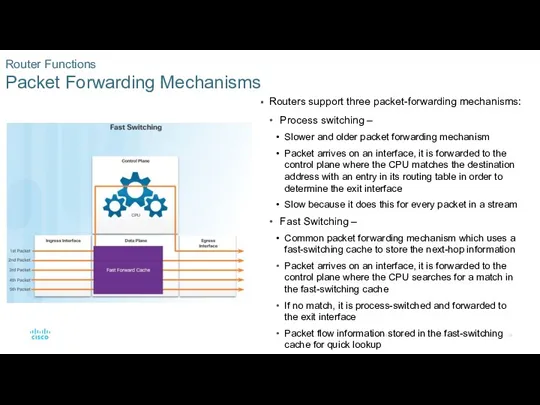
Packet Forwarding Mechanisms
Routers support three packet-forwarding mechanisms:
Process switching –
Slower and
Router Functions
Packet Forwarding Mechanisms
Routers support three packet-forwarding mechanisms:
Process switching –
Slower and
Router Functions
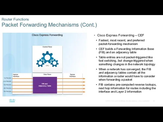
Packet Forwarding Mechanisms (Cont.)
Cisco Express Forwarding – CEF
Fastest, most
Router Functions
Packet Forwarding Mechanisms (Cont.)
Cisco Express Forwarding – CEF
Fastest, most
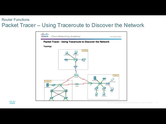
Router Functions
Packet Tracer – Using Traceroute to Discover the Network
Router Functions
Packet Tracer – Using Traceroute to Discover the Network
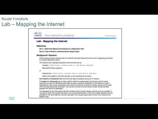
Router Functions
Lab – Mapping the Internet
Router Functions
Lab – Mapping the Internet
Connect Devices
Connect to a Network
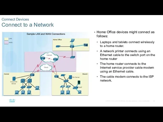
Home Office devices might connect as follows:
Connect Devices
Connect to a Network
Home Office devices might connect as follows:
Connect Devices
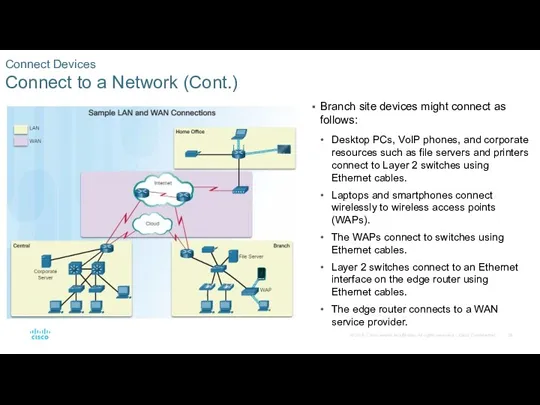
Connect to a Network (Cont.)
Branch site devices might connect as
Connect Devices
Connect to a Network (Cont.)
Branch site devices might connect as
Connect Devices
Connect to a Network (Cont.)
Central site devices might connect as
Connect Devices
Connect to a Network (Cont.)
Central site devices might connect as
Connect Devices
Default Gateways
Devices need the following information for network access: IP
Connect Devices
Default Gateways
Devices need the following information for network access: IP
Connect Devices
Document Network Addressing
When designing a new network or mapping an
Connect Devices
Document Network Addressing
When designing a new network or mapping an
Connect Devices
Enable IP on a Host
A host can be assigned IP
Connect Devices
Enable IP on a Host
A host can be assigned IP
Connect Devices
Device LEDs
Host computers connect to a wired network using a
Connect Devices
Device LEDs
Host computers connect to a wired network using a
Connect Devices
Console Access
Devices including routers and switches are commonly accessed using
Connect Devices
Console Access
Devices including routers and switches are commonly accessed using
Connect Devices
Enable IP on a Switch
Network devices require IP addresses in
Connect Devices
Enable IP on a Switch
Network devices require IP addresses in
Connect Devices
Packet Tracer – Documenting the Network
Connect Devices
Packet Tracer – Documenting the Network
Router Basic Settings
Configure Basic Router Settings
Cisco routers and switches have
Router Basic Settings
Configure Basic Router Settings
Cisco routers and switches have
Router Basic Settings
Configure an IPv4 Router Interface
Layer 2 switches support LANs
Router Basic Settings
Configure an IPv4 Router Interface
Layer 2 switches support LANs
Router Basic Settings
Configure an IPv6 Router Interface
To configure host PC1, statically
Router Basic Settings
Configure an IPv6 Router Interface
To configure host PC1, statically
Router Basic Settings
Configure an IPv6 Router Interface (Cont.)
Unlike IPv4, IPv6 interfaces
Router Basic Settings
Configure an IPv6 Router Interface (Cont.)
Unlike IPv4, IPv6 interfaces
Router Basic Settings
Configure an IPv4 Loopback Interface
An IPv4 loopback interface is
Router Basic Settings
Configure an IPv4 Loopback Interface
An IPv4 loopback interface is
Router Basic Settings
Packet Tracer – Configuring IPv4 and IPv6 Interfaces
Router Basic Settings
Packet Tracer – Configuring IPv4 and IPv6 Interfaces
Verify Connectivity of Directly Connected Networks
Verify Interface Settings
The following commands are
Verify Connectivity of Directly Connected Networks
Verify Interface Settings
The following commands are
Verify Connectivity of Directly Connected Networks
Verify IPv6 Interface Settings
IPv6 commands used
Verify Connectivity of Directly Connected Networks
Verify IPv6 Interface Settings
IPv6 commands used
Verify Connectivity of Directly Connected Networks
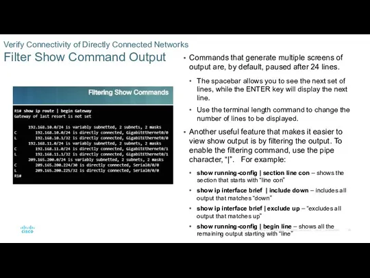
Filter Show Command Output
Commands that generate
Verify Connectivity of Directly Connected Networks
Filter Show Command Output
Commands that generate
Verify Connectivity of Directly Connected Networks
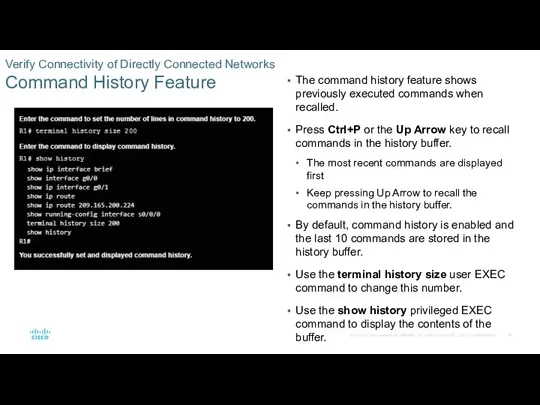
Command History Feature
The command history feature
Verify Connectivity of Directly Connected Networks
Command History Feature
The command history feature
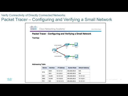
Verify Connectivity of Directly Connected Networks
Packet Tracer – Configuring and Verifying
Verify Connectivity of Directly Connected Networks Packet Tracer – Configuring and Verifying
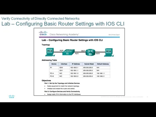
Verify Connectivity of Directly Connected Networks
Lab – Configuring Basic Router Settings
Verify Connectivity of Directly Connected Networks Lab – Configuring Basic Router Settings
1.2 Routing Decisions
1.2 Routing Decisions
Switching Packets Between Networks
Router Switching Function
The primary function of a router
Switching Packets Between Networks
Router Switching Function
The primary function of a router
Switching Packets Between Networks
Router Switching Function (Cont.)
When a router receives a
Switching Packets Between Networks
Router Switching Function (Cont.)
When a router receives a
Switching Packets Between Networks
Send a Packet
For PC1 to send a packet
Switching Packets Between Networks
Send a Packet
For PC1 to send a packet
Switching Packets Between Networks
Forward to the Next Hop
When R1 receives the
Switching Packets Between Networks
Forward to the Next Hop
When R1 receives the
Switching Packets Between Networks
Forward to the Next Hop (Cont.)
When R1 receives
Switching Packets Between Networks
Forward to the Next Hop (Cont.)
When R1 receives
Switching Packets Between Networks
Packet Routing
R2 examines the destination MAC address. Because
Switching Packets Between Networks
Packet Routing
R2 examines the destination MAC address. Because
Switching Packets Between Networks
Packet Routing (Cont.)
The routing table of R2 has
Switching Packets Between Networks
Packet Routing (Cont.)
The routing table of R2 has
Switching Packets Between Networks
Reach the Destination
R3 copies the data link PPP
Switching Packets Between Networks
Reach the Destination
R3 copies the data link PPP
Path Determination
Routing Decisions
The primary function of a router is to determine
Path Determination
Routing Decisions
The primary function of a router is to determine
Path Determination
Best Path
Determining the best path to a destination network involves
Path Determination
Best Path
Determining the best path to a destination network involves
Path Determination
Load Balancing
If a router has two or more paths with
Path Determination
Load Balancing
If a router has two or more paths with
Path Determination
Administrative Distance
If a router has multiple routing protocols configured and
Path Determination
Administrative Distance
If a router has multiple routing protocols configured and
1.3 Router Operation
1.3 Router Operation
Analyze the Routing Table
The Routing Table
The routing table of a router
Analyze the Routing Table
The Routing Table
The routing table of a router
Analyze the Routing Table
Routing Table Sources
On a Cisco router, the show
Analyze the Routing Table
Routing Table Sources
On a Cisco router, the show
Analyze the Routing Table
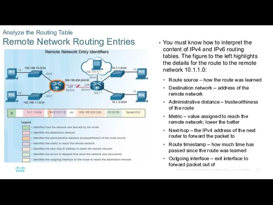
Remote Network Routing Entries
You must know how to
Analyze the Routing Table
Remote Network Routing Entries
You must know how to
Directly Connected Routes
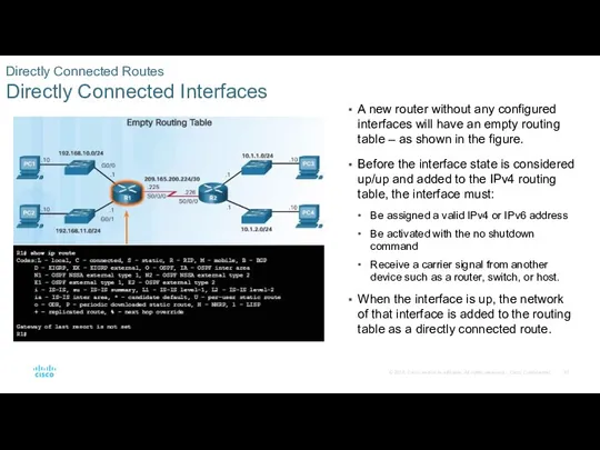
Directly Connected Interfaces
A new router without any configured interfaces
Directly Connected Routes
Directly Connected Interfaces
A new router without any configured interfaces
Directly Connected Routes
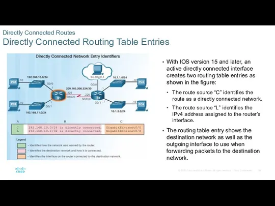
Directly Connected Routing Table Entries
With IOS version 15 and
Directly Connected Routes
Directly Connected Routing Table Entries
With IOS version 15 and
Directly Connected Routes
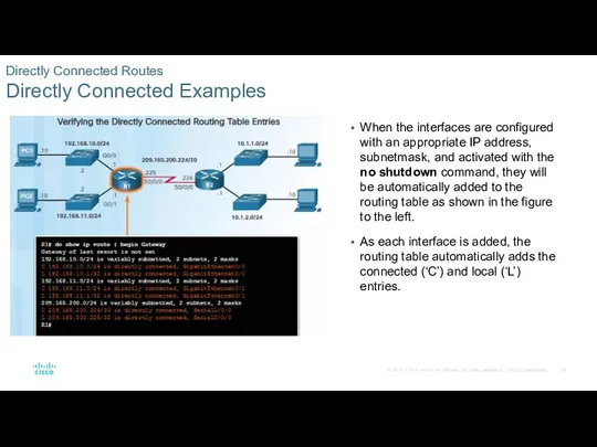
Directly Connected Examples
When the interfaces are configured with an
Directly Connected Routes
Directly Connected Examples
When the interfaces are configured with an
Directly Connected Routes
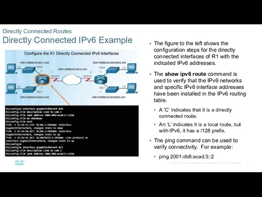
Directly Connected IPv6 Example
The figure to the left shows
Directly Connected Routes
Directly Connected IPv6 Example
The figure to the left shows
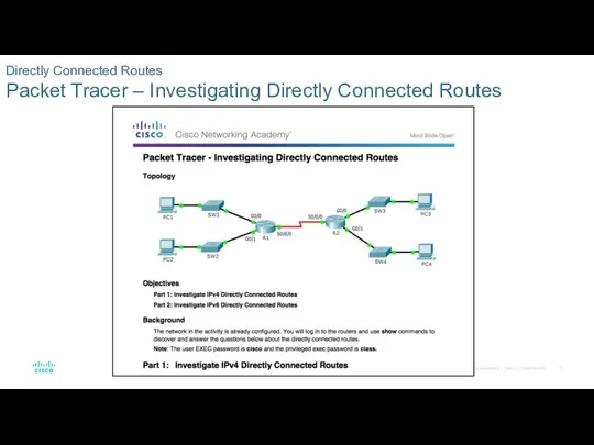
Directly Connected Routes
Packet Tracer – Investigating Directly Connected Routes
Directly Connected Routes
Packet Tracer – Investigating Directly Connected Routes
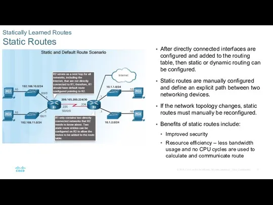
Statically Learned Routes
Static Routes
After directly connected interfaces are configured and added
Statically Learned Routes
Static Routes
After directly connected interfaces are configured and added
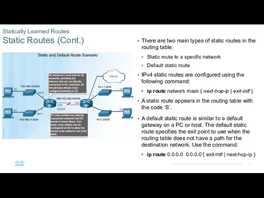
Statically Learned Routes
Static Routes (Cont.)
There are two main types of static
Statically Learned Routes
Static Routes (Cont.)
There are two main types of static
Statically Learned Routes
Static Route Examples
The figure to the left shows the
Statically Learned Routes
Static Route Examples
The figure to the left shows the
Statically Learned Routes
Static IPv6 Route Examples
To configure a default IPv6 static
Statically Learned Routes
Static IPv6 Route Examples
To configure a default IPv6 static
Dynamic Routing Protocols
Dynamic Routing
Dynamic routing protocols are used by routers to
Dynamic Routing Protocols
Dynamic Routing
Dynamic routing protocols are used by routers to
Dynamic Routing Protocols
IPv4 Routing Protocols
One of the major advantages of dynamic
Dynamic Routing Protocols
IPv4 Routing Protocols
One of the major advantages of dynamic
1.4 Summary
1.4 Summary
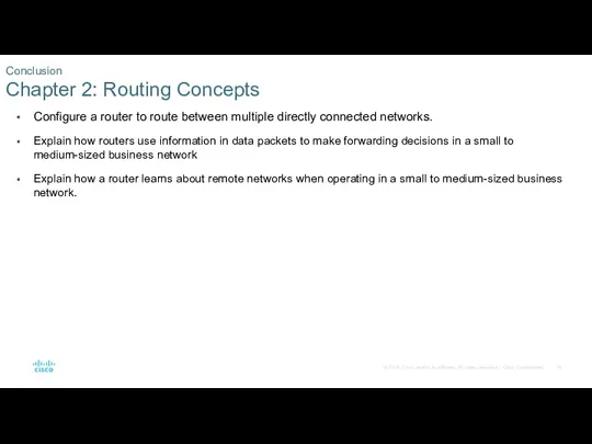
Configure a router to route between multiple directly connected networks.
Explain how
Configure a router to route between multiple directly connected networks.
Explain how
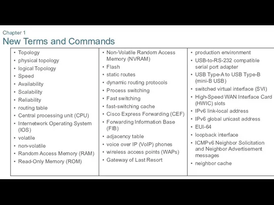
Chapter 1
New Terms and Commands
Chapter 1
New Terms and Commands
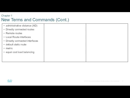
Chapter 1
New Terms and Commands (Cont.)
Chapter 1
New Terms and Commands (Cont.)
 Impeller. Database programming language
 Первые эксперименты по обучению учащихся элементам программирования и кибернетики
 Анализ уязвимостей системы ГНСС
 Типология социальных медиа
 Библиотека. Библиотечная терминология
 Современные сети
 Осторожно! Цивилизация Безопасный Интернет ИГРА
 Принципы и структура системного анализа. Декомпозиция системы
 Использование подзапросов для решения запросов
 Інтерфейс користувача та етапи його розробки
 Журнал Esquire как СМИ
 Повторяющиеся элементы в окружающем мире
 Электронная почта.
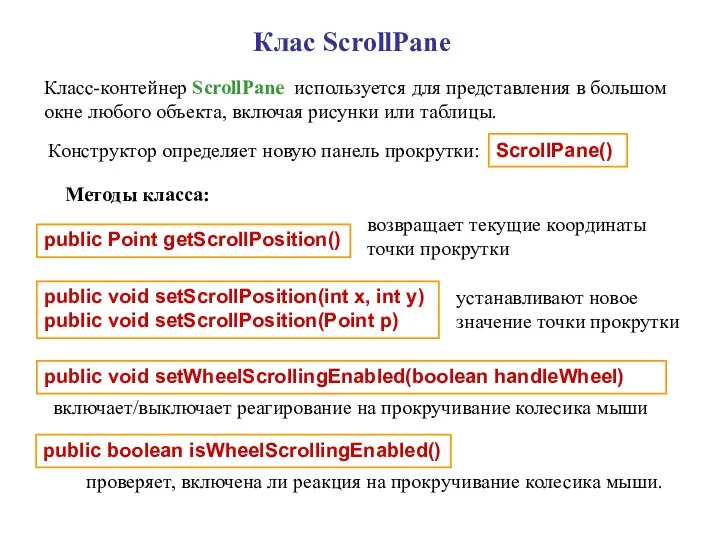 Клас ScrollPane
 High and low level programming languages
 Магнитная запись информации
 Информационные технологии (учебный курс)
 Дополнительные возможности HTML и CSS. XML-технологии и их применение
 Социальные сети
 MS Excel Табличный процесс. MS Excel: возможности, достоинства и недостатки
 Карельский язык в интернете
 Алгоритм Forel. Выделение устойчивых таксонов
 Автоматизация производства
 Технологія WI-FI
 Network foundations
 Автоматизация процессов планирования и учета в производстве в АО Уралтрансмаш на отечественном программном обеспечении
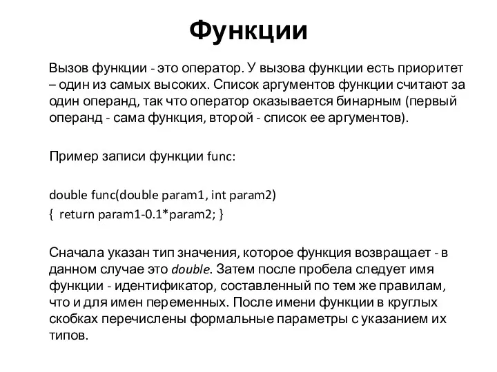 Функции
 Антивирусные программы. Программы-архиваторы