- Standard software training

Содержание
- 2. Purpose to present the Standard Software system and its functionality to end users (operators, technologists, automation
- 3. Automation system Concept The automation control system is based on physical, procedural and recipe model of
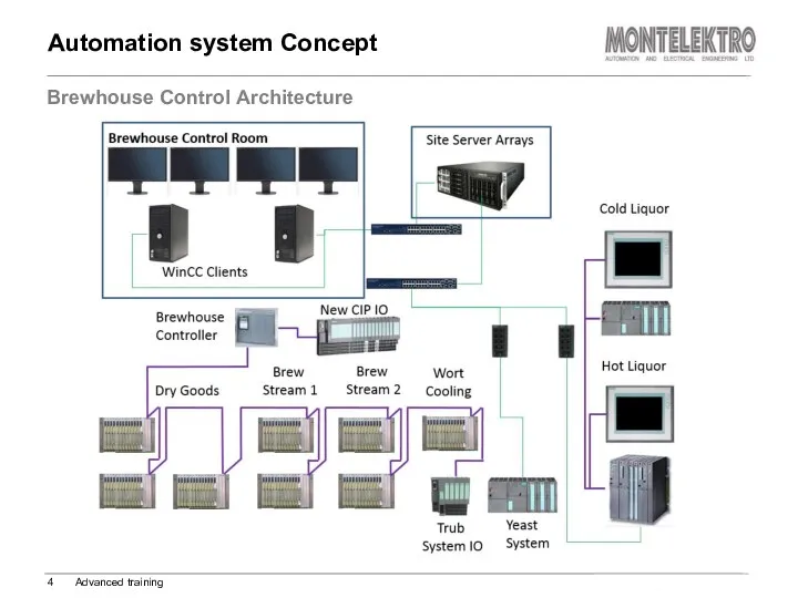
- 4. Automation system Concept Brewhouse Control Architecture Advanced training
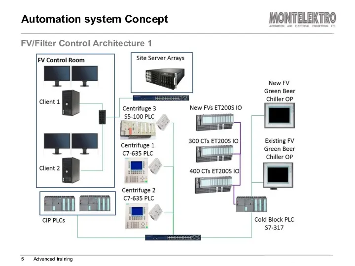
- 5. Automation system Concept FV/Filter Control Architecture 1 Advanced training
- 6. Automation system Concept FV/Filter Control Architecture 2 Advanced training
- 7. PLC Profibus network Automation system Concept Advanced training PLC
- 8. ISA S88 Model ISA S88 - standard for batch control, represents a design philosophy for software,
- 9. ISA S88 Physical Model Process cell (logical grouping of equipment ) required for production of one
- 10. smallest part of the control system that can perform basic control can be physical (valve, pump,
- 11. Valve Double seat valve Two way flap Motorized valve Proportional valve Manual valve pump, motor pump,
- 12. ISA S88 Procedural Model Recipe Procedure - strategy for a major processing action (making a batch)
- 13. ISA S88 Procedural Model Recipe operations or ROPs operations which are a part of the procedure
- 14. ISA S88 Procedural Model Parameters are defined as one of the following types: Manual Proc. Timer
- 15. Process control and supervision Detailed overview of trends and message history Creating and editing of procedures
- 16. SIMATIC WinCC Explorer icon Located on desktop Starts WinCC Runtime containing the Human Machine Interface -
- 17. Log on, change or log off user in the Standard Software system Log on window User
- 18. 1) Header title, customer logo, supplier logo, the last active alarm, actual user name, alarm indicator,
- 19. Header – Process screen tab Operation Manager – Process screen Basic training Following commands are available
- 20. Select process cell in sidebar Navigation within process cell Operation Manager – Navigation Basic training Navigation
- 21. Click on the Montelektro logo on header Select process screen button in the pop-up window Operation
- 22. Screen shows configuration of automation system. The purpose of screen is more informative then operational. Operation
- 23. Available commands on System screen: Operation Manager – System Screen Advanced training 2 1 1 1
- 24. Unit control window Normally placed on the bottom of the process screen Shows all general sequence
- 25. Operation Manager – Unit control Basic training Recipe: The field shows the actual active recipe for
- 26. Operation Manager – Unit control Basic training Unit Commands Start Hold Restart Confirm Fault reset Pop-up
- 27. Operation Manager – Unit commands Window Basic training Contains the whole set of operator commands to
- 28. Operation Manager – Unit parameters Window Basic training Window shows particular unit “Unit parameters”. Unit parameters
- 29. Operation Manager – Recipe parameters Window Basic training Window shows particular unit “ROP parameters”. ROP parameters
- 30. Operation Manager – Unit ROP parameters Window Basic training Window shows particular unit “ROP parameters”. Window
- 31. Smallest part of the control system that can perform basic control Can be physical but also
- 32. This CM represents the valve with one solenoid. It can be equipped with 2 position feedback
- 33. This CM represents the direct controlled motors and pumps. It can be equipped with run feedback
- 34. This CM represents the PID regulator. Operation modes: Automatic, manual, PID manual CM Type 03: PID
- 35. This CM represents the proportional valve with one solenoid. It can be equipped with 2 position
- 36. This CM represents the digital switches. Module contains only one digital input. Operation modes: Automatic, simulation
- 37. This CM represents the analog transmitter. Module contains only one analog input. Operation modes: Automatic, simulation
- 38. This CM represents the motorized valve. It can be equipped with 2 position feedback switches (opened
- 39. This CM represents the valve with two solenoids. It can be equipped with 2 position feedback
- 40. This CM represents two way flap with two solenoids. It can be equipped with 4 position
- 41. This CM represents pulse counting. Module contains only one digital input. Operation modes: Automatic, simulation, pulse
- 42. This CM represents one digital output. Operation modes: Automatic, manual, maintenance, activated, deactivated CM Type 17:
- 43. This CM represents the valve with one solenoid for valve activation and two solenoids for seats.
- 44. This CM represents the Input/Output analog value. Operation modes: Automatic, simulation CM Type 29: Analog Value
- 45. This CM represents the motors and pumps that can run with various range of speed. It
- 46. This CM represents the analog output value. Module contains only one analog output. Operation modes: Automatic,
- 47. Authorisation level example – CM01 Basic Training
- 48. Operation Manager - Alarms Displays active or not confirmed alarms in entire system. Alarm types: High
- 49. Operation Manager - Alarms Basic training Alarms toolbar Commands explanation: 1. Message list: Shows currently active
- 50. Operation Manager - Alarms Advanced training Alarm filtering options Commands explanation: 1. Displays messages between selected
- 51. Operation Manager - Trends Each process screen contains a desired number of Trend buttons. Each trend
- 52. Operation Manager - Trends Basic training Trends header Commands explanation: 1. Trend window properties 2. 3.
- 53. Operation Manager - Trends Advanced training Adding trends Historical trend properties window is called via icon
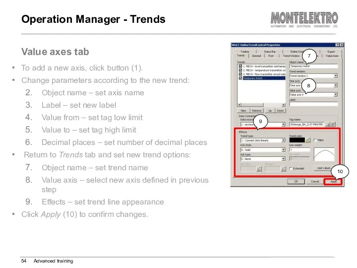
- 54. Operation Manager - Trends Advanced training Value axes tab To add a new axis, click button
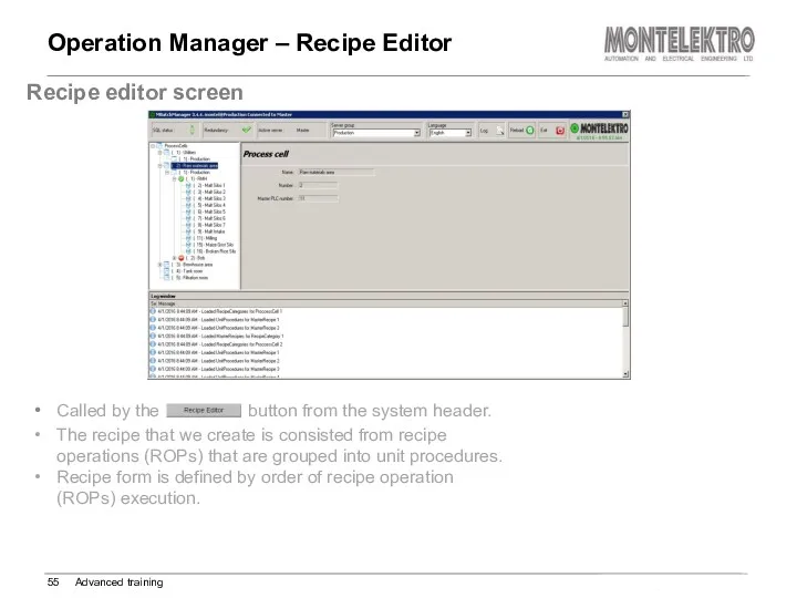
- 55. Operation Manager – Recipe Editor Advanced training Recipe editor screen Called by the button from the
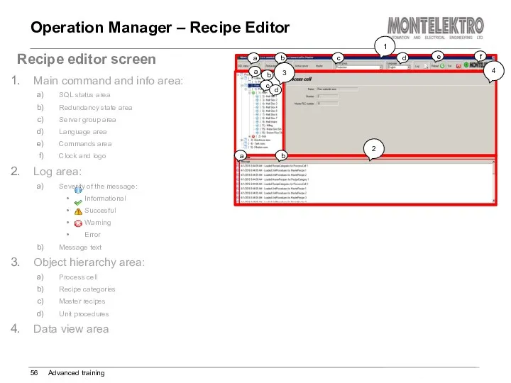
- 56. Operation Manager – Recipe Editor Advanced training Recipe editor screen Main command and info area: SQL
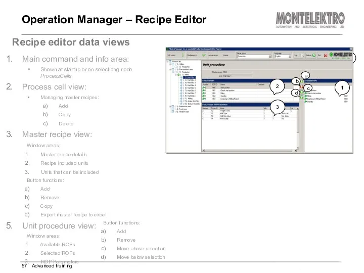
- 57. Operation Manager – Recipe Editor Advanced training Recipe editor data views Main command and info area:
- 58. Operation Manager – Batch Manager Advanced training Production Scheduler screen Application used to schedule batches. Main
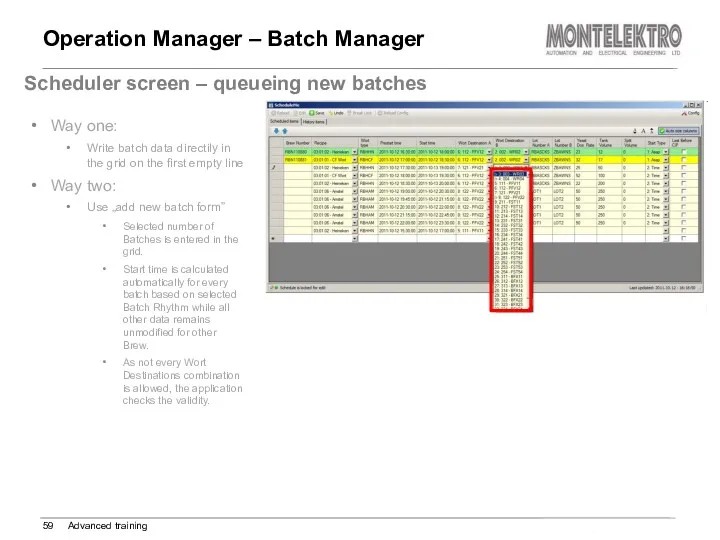
- 59. Operation Manager – Batch Manager Advanced training Scheduler screen – queueing new batches Way one: Write
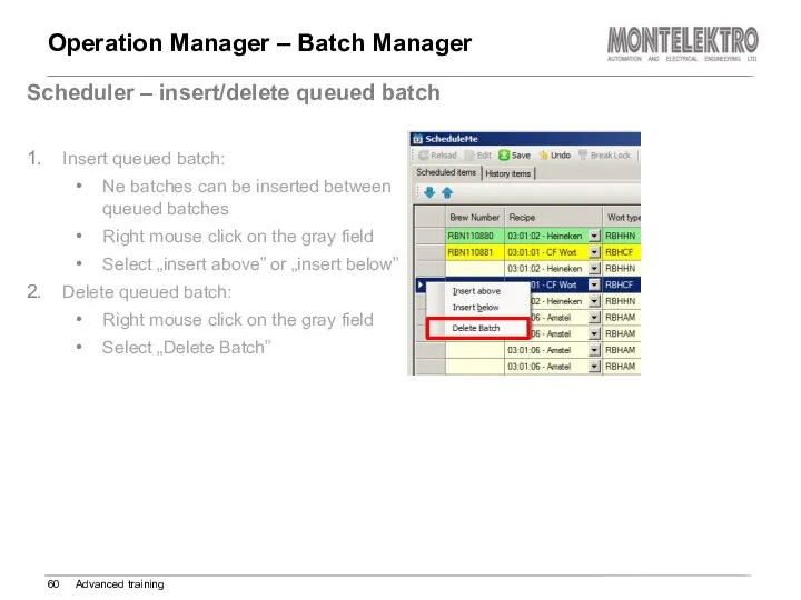
- 60. Operation Manager – Batch Manager Advanced training Scheduler – insert/delete queued batch Insert queued batch: Ne
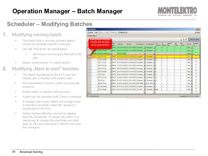
- 61. Operation Manager – Batch Manager Advanced training Scheduler – Modifying Batches Modifying running batch: The Batch
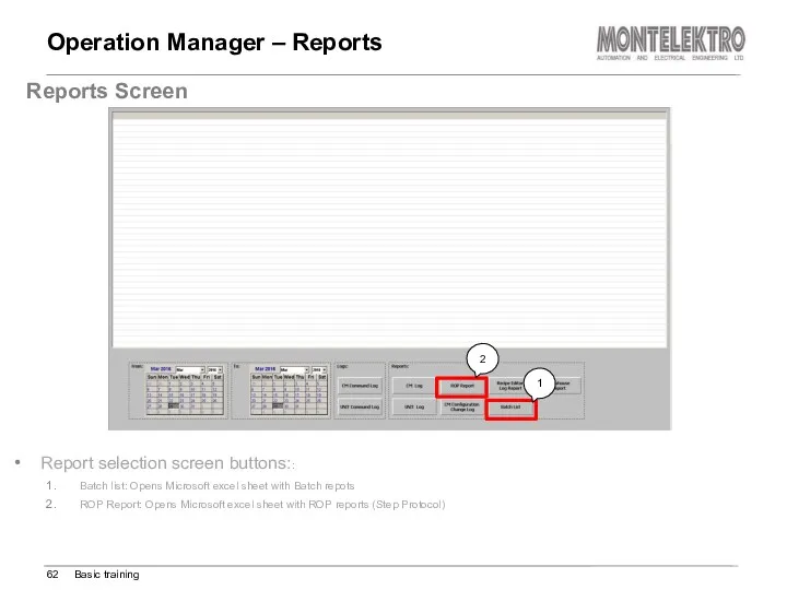
- 62. Operation Manager – Reports Basic training Reports Screen Report selection screen buttons:: Batch list: Opens Microsoft
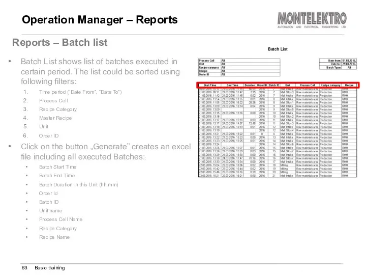
- 63. Operation Manager – Reports Basic training Reports – Batch list Batch List shows list of batches
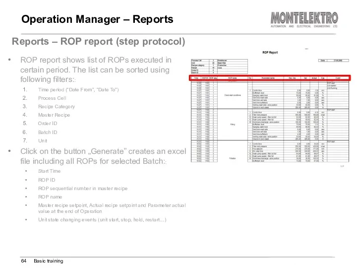
- 64. Operation Manager – Reports Basic training Reports – ROP report (step protocol) ROP report shows list
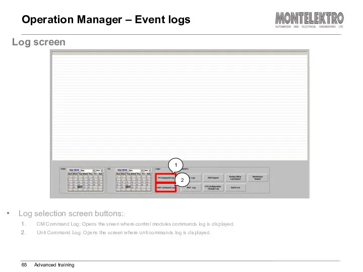
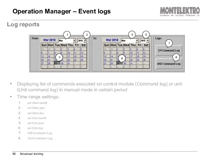
- 65. Operation Manager – Event logs Advanced training Log screen Log selection screen buttons:: CM Command Log:
- 66. Operation Manager – Event logs Advanced training Log reports Displaying list of commands executed on control
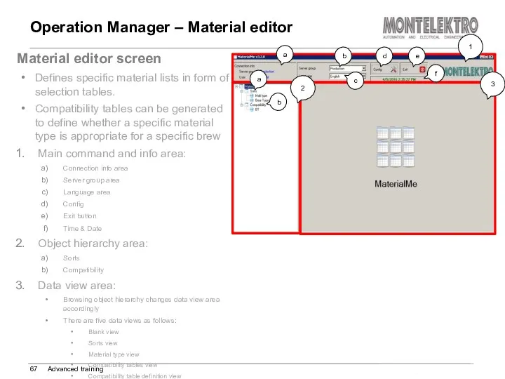
- 67. Operation Manager – Material editor Advanced training Material editor screen Defines specific material lists in form
- 68. Operation Manager – Material editor Advanced training Material editor Blank view Shown on startup or on
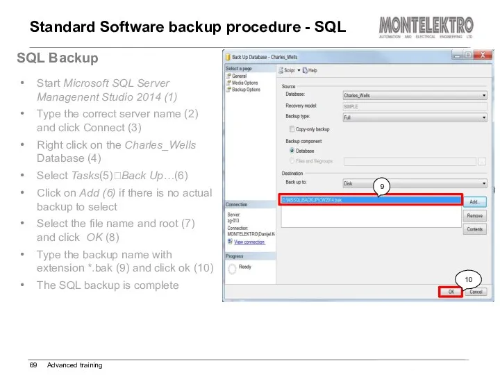
- 69. Standard Software backup procedure - SQL Advanced training SQL Backup Start Microsoft SQL Server Managenent Studio
- 70. Standard Software backup procedure Advanced training Standard Software Backup Go to the location on the Master
- 72. Скачать презентацию
Purpose
to present the Standard Software system and its functionality to end
to present the Standard Software system and its functionality to end
Automation system Concept
The automation control system is based on physical, procedural
Automation system Concept
The automation control system is based on physical, procedural
Automation system Concept
Brewhouse Control Architecture
Advanced training
Automation system Concept
Brewhouse Control Architecture
Advanced training
Automation system Concept
FV/Filter Control Architecture 1
Advanced training
Automation system Concept
FV/Filter Control Architecture 1
Advanced training
Automation system Concept
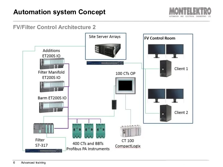
FV/Filter Control Architecture 2
Advanced training
Automation system Concept
FV/Filter Control Architecture 2
Advanced training
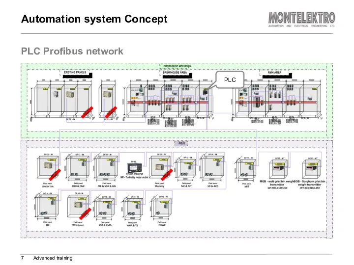
PLC Profibus network
Automation system Concept
Advanced training
PLC
PLC Profibus network
Automation system Concept
Advanced training
PLC
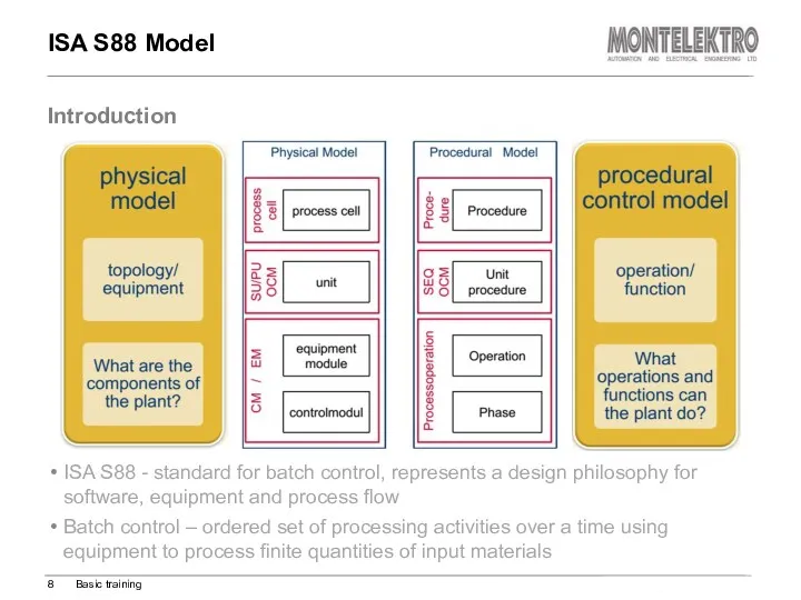
ISA S88 Model
ISA S88 - standard for batch control, represents a
ISA S88 Model
ISA S88 - standard for batch control, represents a
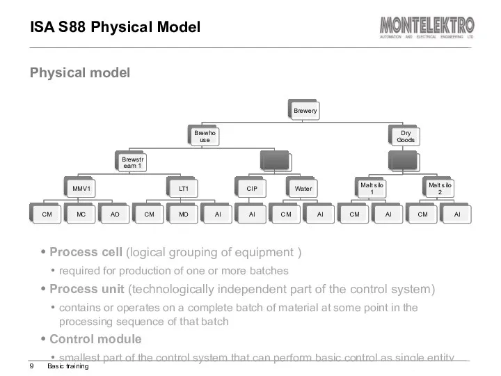
ISA S88 Physical Model
Process cell (logical grouping of equipment )
required for
ISA S88 Physical Model
Process cell (logical grouping of equipment )
required for
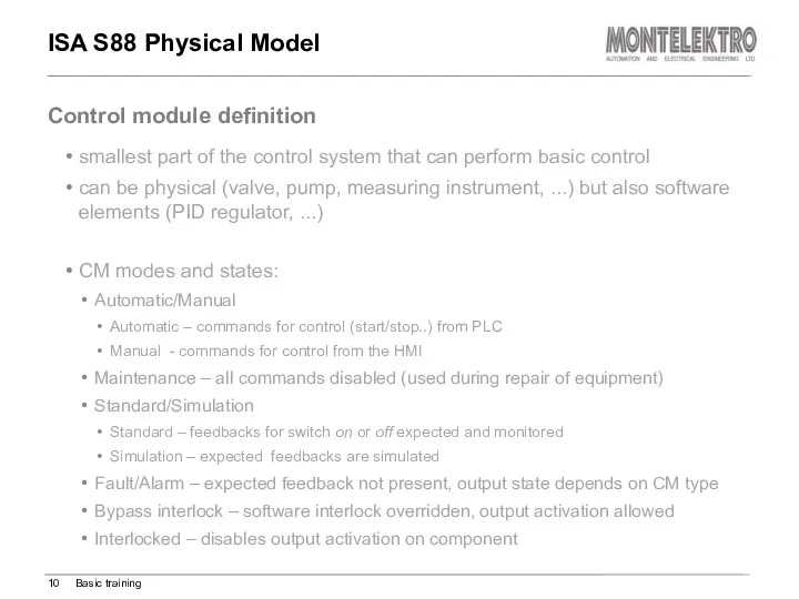
smallest part of the control system that can perform basic control
smallest part of the control system that can perform basic control
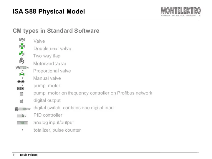
Valve
Double seat valve
Two way flap
Motorized valve
Proportional valve
Manual valve
pump, motor
pump, motor
Valve
Double seat valve
Two way flap
Motorized valve
Proportional valve
Manual valve
pump, motor
pump, motor
ISA S88 Procedural Model
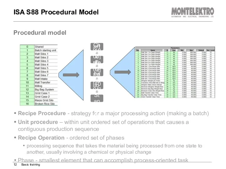
Recipe Procedure - strategy for a major processing
ISA S88 Procedural Model
Recipe Procedure - strategy for a major processing
ISA S88 Procedural Model
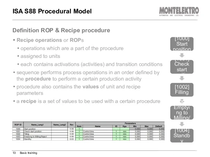
Recipe operations or ROPs
operations which are a part
ISA S88 Procedural Model
Recipe operations or ROPs
operations which are a part
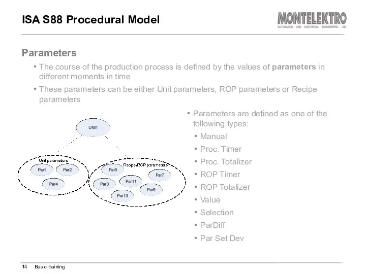
ISA S88 Procedural Model
Parameters are defined as one of the following
ISA S88 Procedural Model
Parameters are defined as one of the following
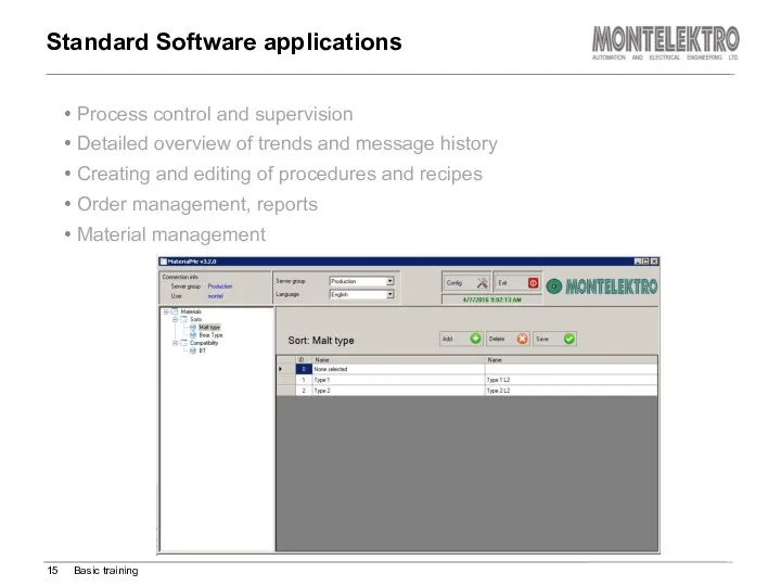
Process control and supervision
Detailed overview of trends and message history
Creating and
Process control and supervision
Detailed overview of trends and message history
Creating and
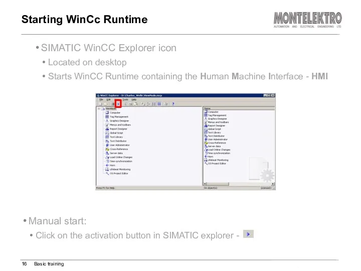
SIMATIC WinCC Explorer icon
Located on desktop
Starts WinCC Runtime containing the Human
SIMATIC WinCC Explorer icon
Located on desktop
Starts WinCC Runtime containing the Human
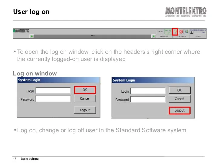
Log on, change or log off user in the Standard Software
Log on, change or log off user in the Standard Software
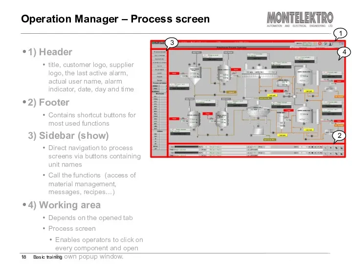
1) Header
title, customer logo, supplier logo, the last active alarm,
1) Header
title, customer logo, supplier logo, the last active alarm,
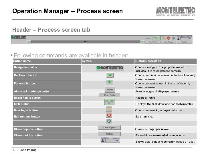
Header – Process screen tab
Operation Manager – Process screen
Basic
Header – Process screen tab
Operation Manager – Process screen
Basic
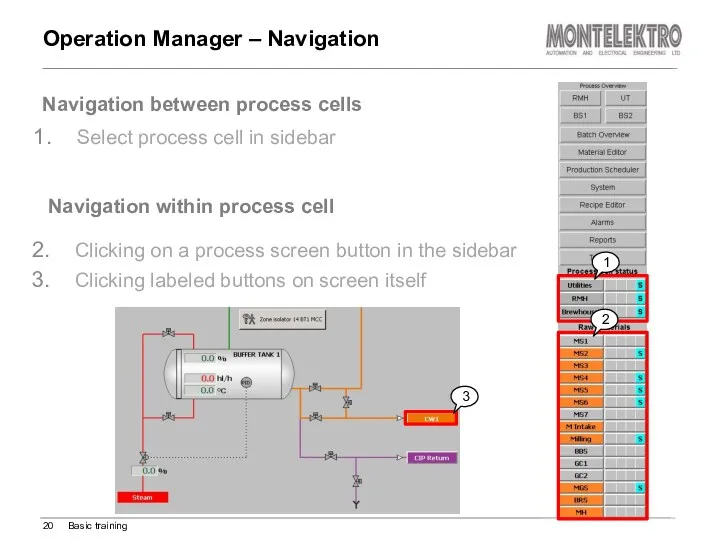
Select process cell in sidebar
Navigation within process cell
Operation Manager –
Select process cell in sidebar
Navigation within process cell
Operation Manager –
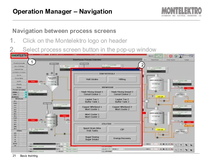
Click on the Montelektro logo on header
Select process screen button in
Click on the Montelektro logo on header
Select process screen button in
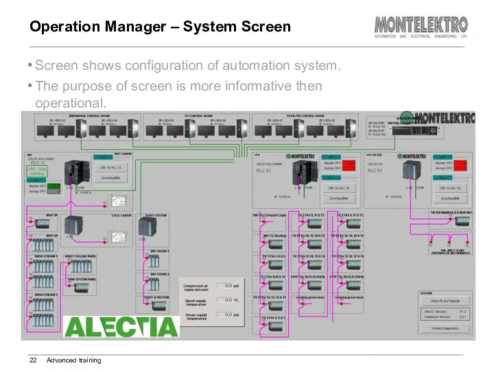
Screen shows configuration of automation system.
The purpose of screen is
Screen shows configuration of automation system.
The purpose of screen is
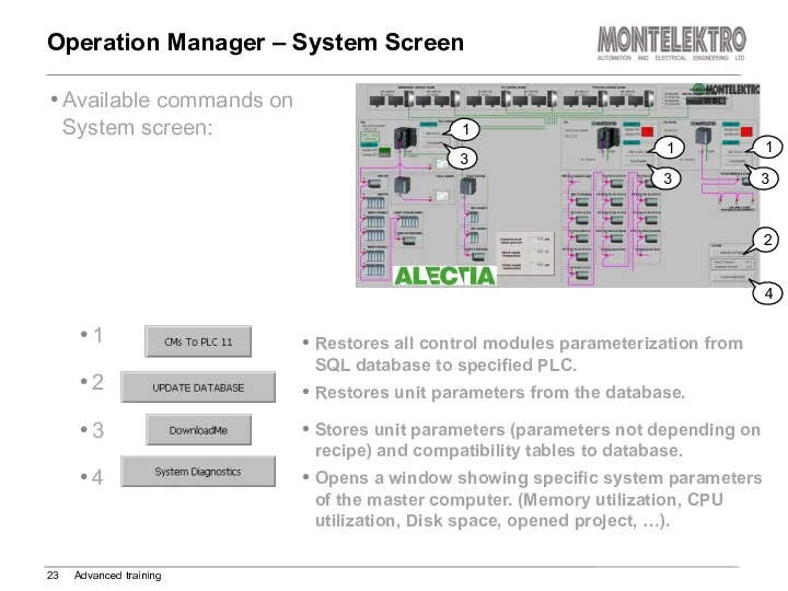
Available commands on System screen:
Operation Manager – System Screen
Advanced training
2
1
1
1
3
3
3
4
1
2
3
4
Restores
Available commands on System screen:
Operation Manager – System Screen
Advanced training
2
1
1
1
3
3
3
4
1
2
3
4
Restores
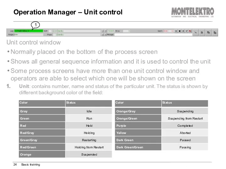
Unit control window
Normally placed on the bottom of the process screen
Shows
Unit control window
Normally placed on the bottom of the process screen
Shows
Operation Manager – Unit control
Basic training
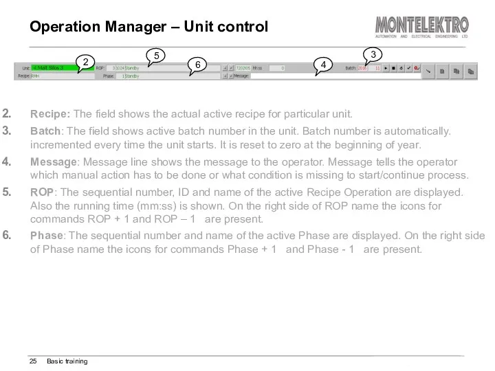
Recipe: The field shows the
Operation Manager – Unit control
Basic training
Recipe: The field shows the
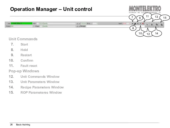
Operation Manager – Unit control
Basic training
Unit Commands
Start
Hold
Restart
Confirm
Fault reset
Pop-up Windows
Unit Commands
Operation Manager – Unit control
Basic training
Unit Commands
Start
Hold
Restart
Confirm
Fault reset
Pop-up Windows
Unit Commands
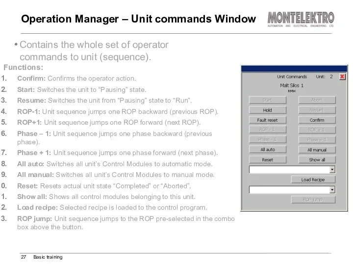
Operation Manager – Unit commands Window
Basic training
Contains the whole set
Operation Manager – Unit commands Window
Basic training
Contains the whole set
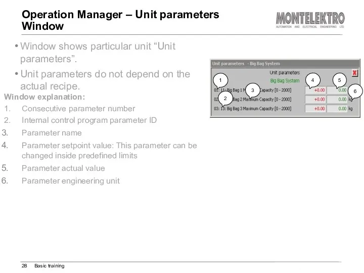
Operation Manager – Unit parameters
Window
Basic training
Window shows particular unit
Operation Manager – Unit parameters
Window
Basic training
Window shows particular unit
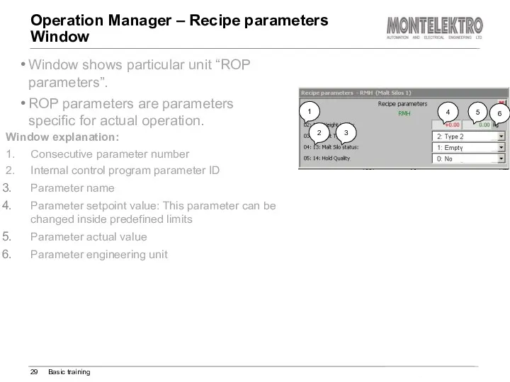
Operation Manager – Recipe parameters
Window
Basic training
Window shows particular unit
Operation Manager – Recipe parameters
Window
Basic training
Window shows particular unit
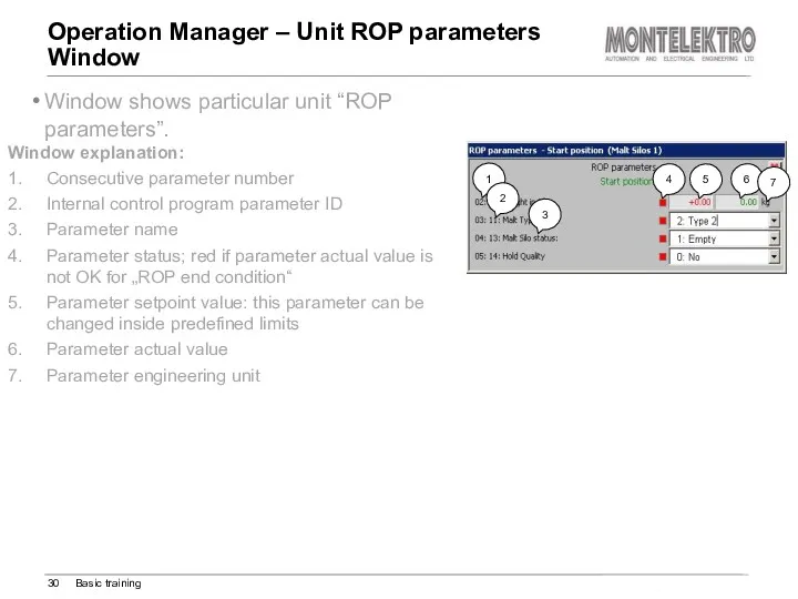
Operation Manager – Unit ROP parameters
Window
Basic training
Window shows particular
Operation Manager – Unit ROP parameters
Window
Basic training
Window shows particular
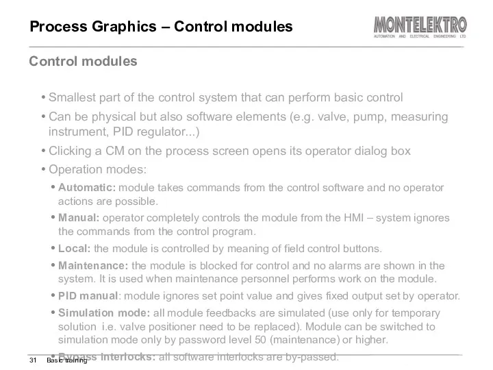
Smallest part of the control system that can perform basic control
Smallest part of the control system that can perform basic control
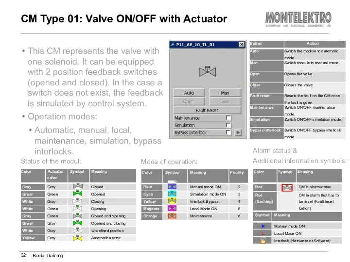
This CM represents the valve with one solenoid. It can be
This CM represents the valve with one solenoid. It can be
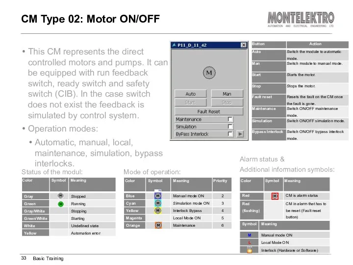
This CM represents the direct controlled motors and pumps. It can
This CM represents the direct controlled motors and pumps. It can
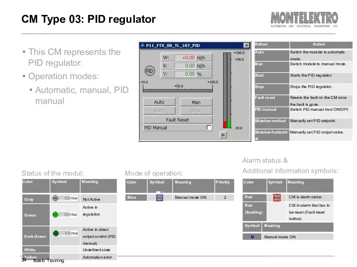
This CM represents the PID regulator.
Operation modes:
Automatic, manual, PID manual
CM Type
This CM represents the PID regulator.
Operation modes:
Automatic, manual, PID manual
CM Type
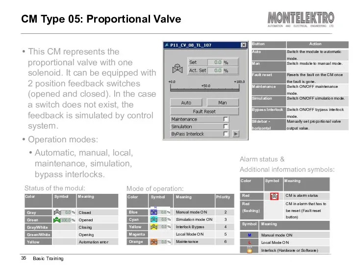
This CM represents the proportional valve with one solenoid. It can
This CM represents the proportional valve with one solenoid. It can
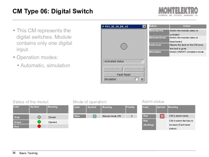
This CM represents the digital switches. Module contains only one digital
This CM represents the digital switches. Module contains only one digital
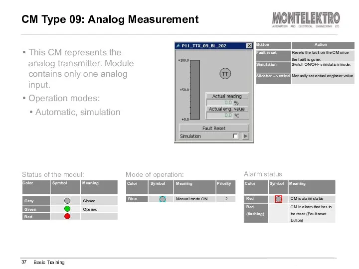
This CM represents the analog transmitter. Module contains only one analog
This CM represents the analog transmitter. Module contains only one analog
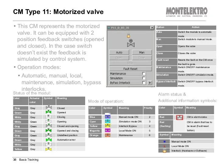
This CM represents the motorized valve. It can be equipped with
This CM represents the motorized valve. It can be equipped with
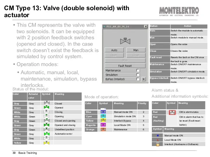
This CM represents the valve with two solenoids. It can be
This CM represents the valve with two solenoids. It can be
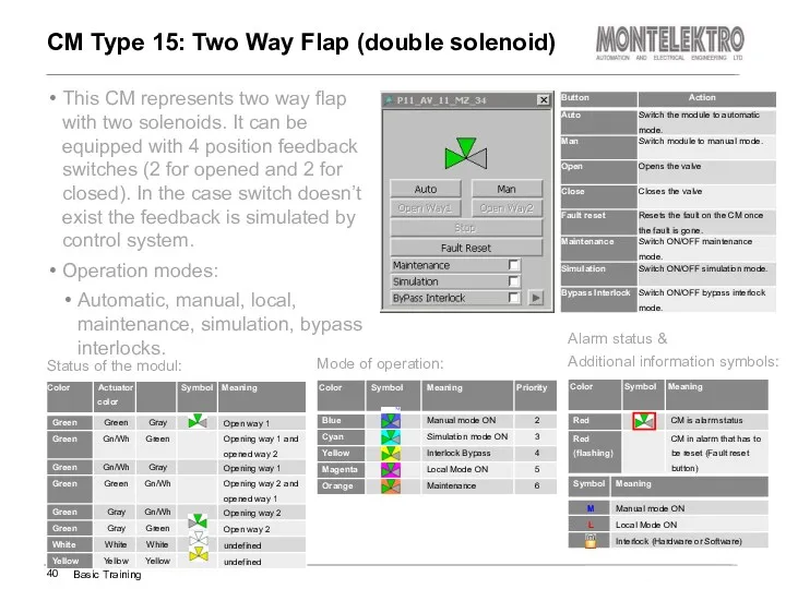
This CM represents two way flap with two solenoids. It can
This CM represents two way flap with two solenoids. It can
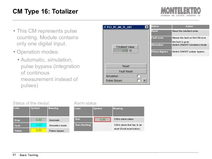
This CM represents pulse counting. Module contains only one digital input.
Operation
This CM represents pulse counting. Module contains only one digital input.
Operation
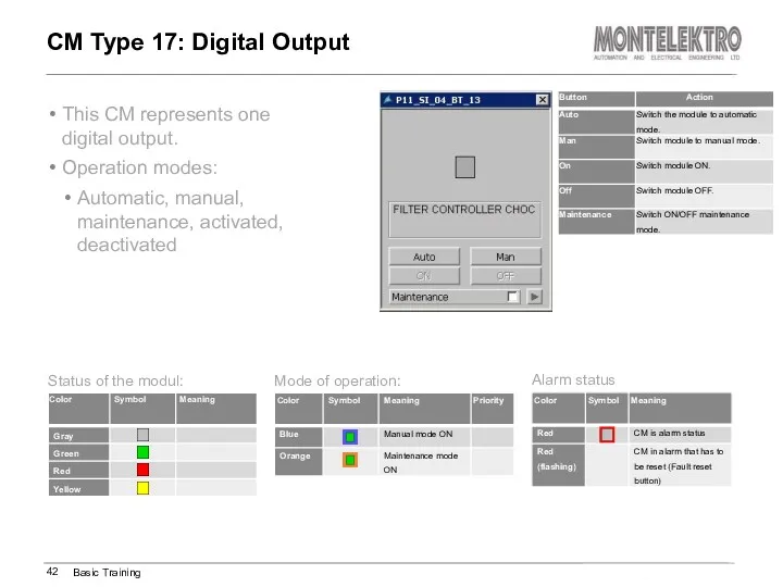
This CM represents one digital output.
Operation modes:
Automatic, manual, maintenance, activated, deactivated
CM
This CM represents one digital output.
Operation modes:
Automatic, manual, maintenance, activated, deactivated
CM
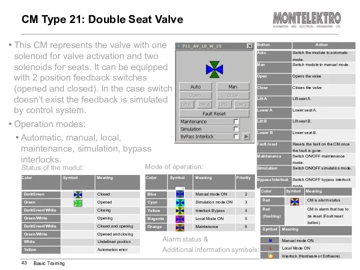
This CM represents the valve with one solenoid for valve activation
This CM represents the valve with one solenoid for valve activation
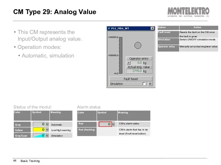
This CM represents the Input/Output analog value.
Operation modes:
Automatic, simulation
CM Type 29:
This CM represents the Input/Output analog value.
Operation modes:
Automatic, simulation
CM Type 29:
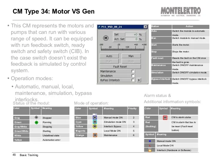
This CM represents the motors and pumps that can run with
This CM represents the motors and pumps that can run with
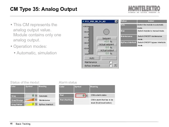
This CM represents the analog output value. Module contains only one
This CM represents the analog output value. Module contains only one
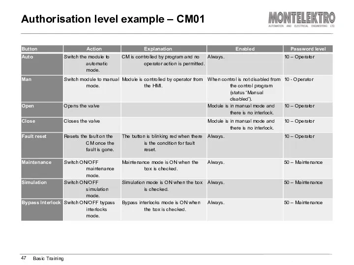
Authorisation level example – CM01
Basic Training
Authorisation level example – CM01
Basic Training
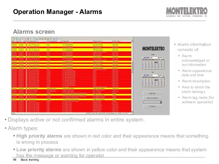
Operation Manager - Alarms
Displays active or not confirmed alarms in entire
Operation Manager - Alarms
Displays active or not confirmed alarms in entire
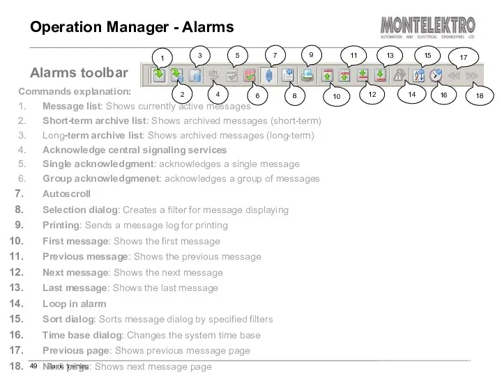
Operation Manager - Alarms
Basic training
Alarms toolbar
Commands explanation:
1. Message list: Shows currently
Operation Manager - Alarms
Basic training
Alarms toolbar
Commands explanation:
1. Message list: Shows currently
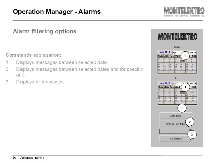
Operation Manager - Alarms
Advanced training
Alarm filtering options
Commands explanation:
1. Displays messages between
Operation Manager - Alarms
Advanced training
Alarm filtering options
Commands explanation:
1. Displays messages between
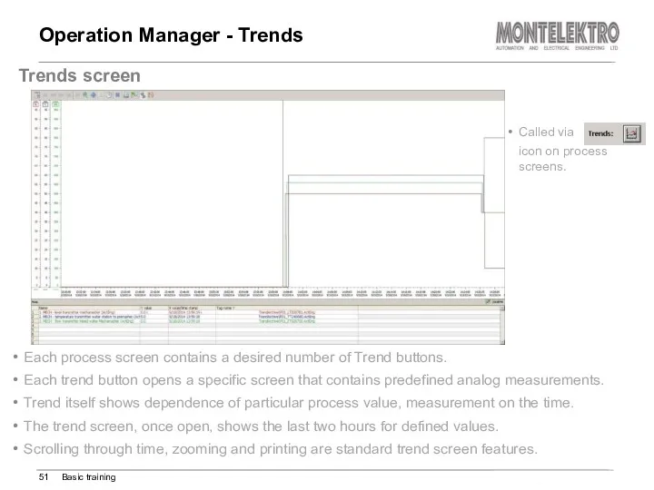
Operation Manager - Trends
Each process screen contains a desired number of
Operation Manager - Trends
Each process screen contains a desired number of
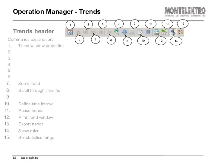
Operation Manager - Trends
Basic training
Trends header
Commands explanation:
1. Trend window properties
2.
3.
Operation Manager - Trends
Basic training
Trends header
Commands explanation:
1. Trend window properties
2.
3.
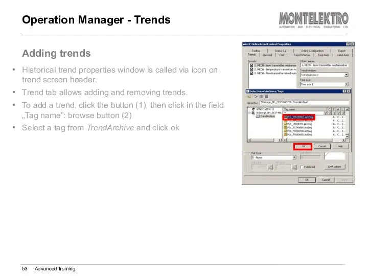
Operation Manager - Trends
Advanced training
Adding trends
Historical trend properties window is
Operation Manager - Trends
Advanced training
Adding trends
Historical trend properties window is
Operation Manager - Trends
Advanced training
Value axes tab
To add a new
Operation Manager - Trends
Advanced training
Value axes tab
To add a new
Operation Manager – Recipe Editor
Advanced training
Recipe editor screen
Called by the
Operation Manager – Recipe Editor
Advanced training
Recipe editor screen
Called by the
Operation Manager – Recipe Editor
Advanced training
Recipe editor screen
Main command and
Operation Manager – Recipe Editor
Advanced training
Recipe editor screen
Main command and
Operation Manager – Recipe Editor
Advanced training
Recipe editor data views
Main command
Operation Manager – Recipe Editor
Advanced training
Recipe editor data views
Main command
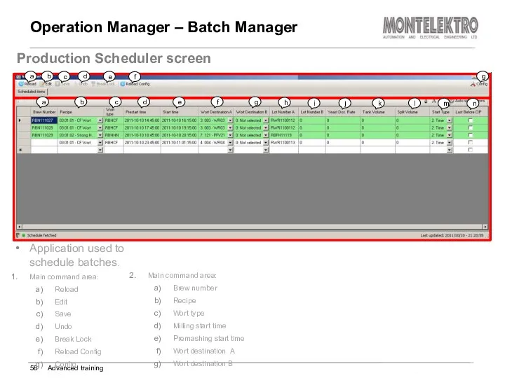
Operation Manager – Batch Manager
Advanced training
Production Scheduler screen
Application used to
Operation Manager – Batch Manager
Advanced training
Production Scheduler screen
Application used to
Operation Manager – Batch Manager
Advanced training
Scheduler screen – queueing new
Operation Manager – Batch Manager
Advanced training
Scheduler screen – queueing new
Operation Manager – Batch Manager
Advanced training
Scheduler – insert/delete queued batch
Operation Manager – Batch Manager
Advanced training
Scheduler – insert/delete queued batch
Operation Manager – Batch Manager
Advanced training
Scheduler – Modifying Batches
Modifying running
Operation Manager – Batch Manager
Advanced training
Scheduler – Modifying Batches
Modifying running
Operation Manager – Reports
Basic training
Reports Screen
Report selection screen buttons::
Batch list:
Operation Manager – Reports
Basic training
Reports Screen
Report selection screen buttons::
Batch list:
Operation Manager – Reports
Basic training
Reports – Batch list
Batch List shows
Operation Manager – Reports
Basic training
Reports – Batch list
Batch List shows
Operation Manager – Reports
Basic training
Reports – ROP report (step protocol)
ROP
Operation Manager – Reports
Basic training
Reports – ROP report (step protocol)
ROP
Operation Manager – Event logs
Advanced training
Log screen
Log selection screen buttons::
CM
Operation Manager – Event logs
Advanced training
Log screen
Log selection screen buttons::
CM
Operation Manager – Event logs
Advanced training
Log reports
Displaying list of commands
Operation Manager – Event logs
Advanced training
Log reports
Displaying list of commands
Operation Manager – Material editor
Advanced training
Material editor screen
Defines specific material
Operation Manager – Material editor
Advanced training
Material editor screen
Defines specific material
Operation Manager – Material editor
Advanced training
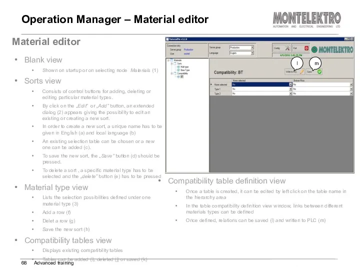
Material editor
Blank view
Shown on
Operation Manager – Material editor
Advanced training
Material editor
Blank view
Shown on
Standard Software backup procedure - SQL
Advanced training
SQL Backup
Start Microsoft SQL
Standard Software backup procedure - SQL
Advanced training
SQL Backup
Start Microsoft SQL
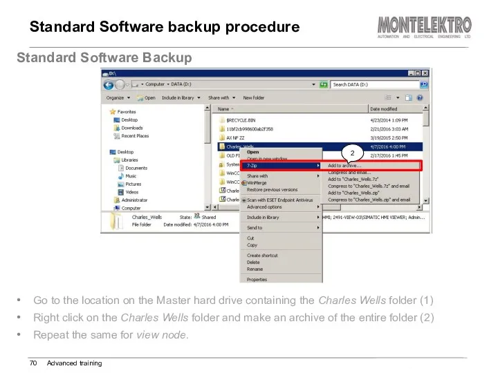
Standard Software backup procedure
Advanced training
Standard Software Backup
Go to the
Standard Software backup procedure
Advanced training
Standard Software Backup
Go to the
 Инструкция по работе с анкетой Naumen
 Пополнение карты Стрелка в мобильном приложении
 нформационные ресурсы общества Информационные услуги и продукты
 Как вебмастеру выжить в условиях кризиса
 Как устроена компьютерная сеть
 Анализ и синтез систем
 Объектно-ориентированное программирование. Практические работы Pascal ABC
 Інтернет. Громадянська освіта. 10 клас
 Pro-women.ru — организация для влияния на социально-образовательные экосистемы людей
 Производственная практика. ADO.NET и COM при работе с MS ACCESS и MS EXCEL в десктопном приложении
 Обработка исключительных ситуаций
 Word 2007: спецкурс
 Технология объектно-ориентированного проектирования ИС (разработки программного обеспечения) – Rational Unified Process (RUP)
 Инновационные модели деятельности школьного библиотекаря по формированию экологической культуры у детей
 Алгоритмизация и программирование (лекция)
 Средства общения в сети Интернет
 Опыт внедрения системы электронного документооборота Правительства Ульяновской области
 Урок по теме Сортировка, удаление и добавление записей 8 класс
 Возможности 3D технологий
 Принципы работы протоколов разных уровней. . Стеки OSI, TCP/IP, IPX/SPX, NetBIOS/SMB. (Тема 11)
 Принципы обработки информации компьютером. Арифметические и логические основы работы компьютера. Лекция 5
 Компьютерное моделирование
 Кибербуллинг
 C++ для ЕГЭ
 Электронные таблицы MS Excel
 Стандартные приложения ОС Windows. Работа с файлами и папками
 Динамические структуры данных: очереди и стеки
 Сервер DHCP и его назначение