- Технология Ethernet для сетей доступа и транспорта

Содержание
- 2. Содержание 1. Технология Ethernet 2. Виртуальные локальные сети VLAN 3. Технология Carrier Ethernet для транспортных сетей
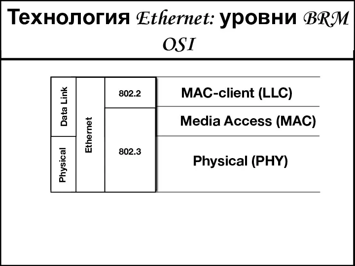
- 3. Технология Ethernet: уровни BRM OSI Data Link Physical Ethernet 802.2 802.3 Physical (PHY) Media Access (MAC)
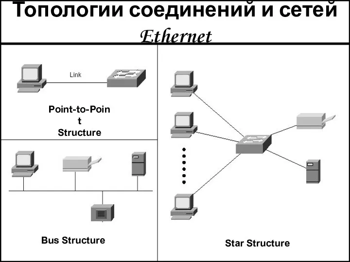
- 4. Топологии соединений и сетей Ethernet Star Structure Bus Structure Point-to-Point Structure
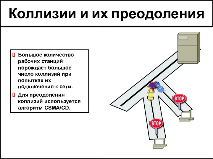
- 5. Коллизии и их преодоления Большое количество рабочих станций порождает большое число коллизий при попытках их подключения
- 6. Hub operation 1. NIC sends a frame. 2.The NIC loops the sent frame onto its receive
- 7. Организация дуплексных связей Преимущества дуплексного режима: Коллизии не возникают. Отсутствует задержка ответа, связанная с ожиданием окончания
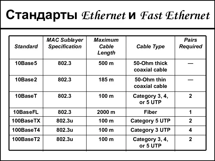
- 8. Стандарты Ethernet и Fast Ethernet
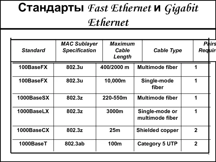
- 9. Стандарты Fast Ethernet и Gigabit Ethernet
- 10. Уровень звена данных Ethernet: форматы кадров
- 11. Общий формат кадров SFD Fixed sequence to alert the receiver DA Destination MAC address SA Source
- 12. Формат кадра Ethernet по IEEE 802.3 Based on type or length field Frame length ( =1536)
- 13. Сравнение форматов Data Source add FCS Length Dest add 46-1500 2 6 6 4 0000.0C xx.xxxx
- 14. Кодирование поля «тип» DA SA Type P A Y L O A D (46–1500 Bytes) 0806
- 15. Правила формирования полей «длина» и «тип» Ethernet version 2 (Xerox) MAC frame has Ethertype field indicates
- 16. Формат кадра с заголовком 802.2 LLC Defining Service Access Points (SAPs) SAPs ensure that the same
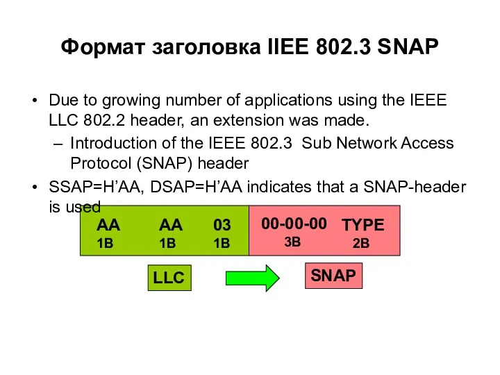
- 17. SNAP Формат заголовка IIEE 802.3 SNAP Due to growing number of applications using the IEEE LLC
- 18. Формат кадра с заголовками 802.2 LLC/ 802.3 SNAP header Type field provides backwards compatibility with Ethernet
- 19. Варианты инкапсуляции IP пакета 0800 IP datagram Preamble (8 bytes) Destination Address (6 bytes) Source Address
- 20. Gigabit Ethernet Frame Format Data Source add FCS Length Dest add 46-1500 2 6 6 4
- 21. Адресация данных в LAN Unicast Binary: 00110101 01111011 00010010 00000000 00000000 00000001 Hex: AC-DE-48-00-00-80 Multicast Binary:
- 22. Коммутация по физическим адресам В каждом сегменте могут возникать свои собственные коллизии. В режиме broadcast коммутатор
- 23. Три процедуры при коммутации пакетов Изучение адресов уровня звена данных. Решение о выборе класса пересылки пакетов.
- 24. How Switches Learn Host Locations В начале инсталляции сети таблица MAC адресов (таблица коммутации) пуста. MAC
- 25. How Switches Learn Hosts Locations Станция A передает кадр станции C. В кадре станция A указывается
- 26. How Switches Learn Host Locations Станция D посылает кадр со своим MAC адресом и Switch заносит
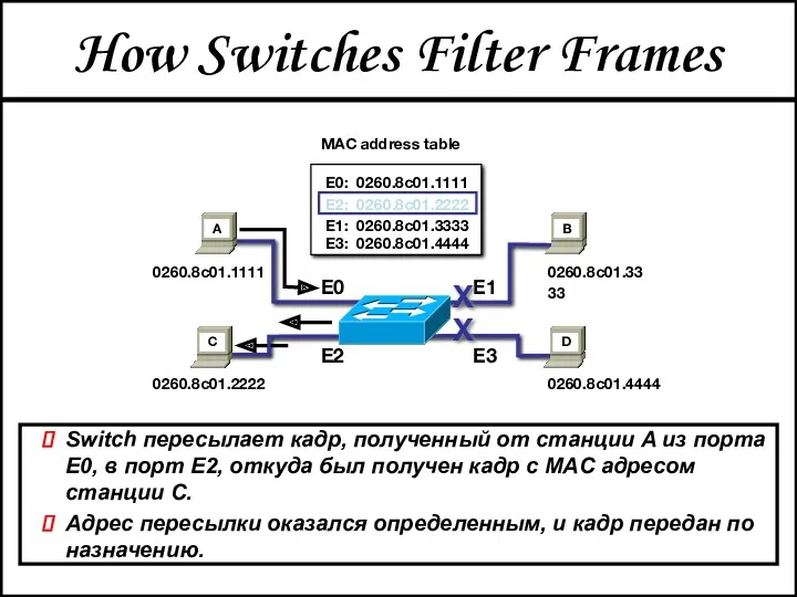
- 27. How Switches Filter Frames Switch пересылает кадр, полученный от станции A из порта E0, в порт
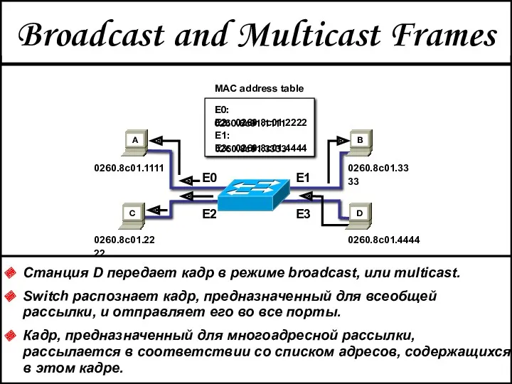
- 28. Broadcast and Multicast Frames Станция D передает кадр в режиме broadcast, или multicast. Switch распознает кадр,
- 29. Ethernet: организация виртуальных локальных сетей (VLAN)
- 30. VLAN = Broadcast Domain = Logical Network (Subnet) Иллюстрация организации VLANs Segmentation Flexibility Security
- 31. Определение VLAN Virtual Local Area Network VLAN Used to separate the physical LAN into logical LANs
- 32. Преимущества VLAN Performance VLANs free up bandwidth by limiting traffic. Formation of Virtual Workgroups Users and
- 33. Способы организации VLAN VLAN can be distinguished by the method used to indicate membership when a
- 34. VLAN 1 уровня: по порту подключения Membership in a VLAN is defined based on the ports
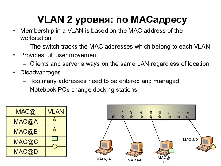
- 35. VLAN 2 уровня: по MACадресу Membership in a VLAN is based on the MAC address of
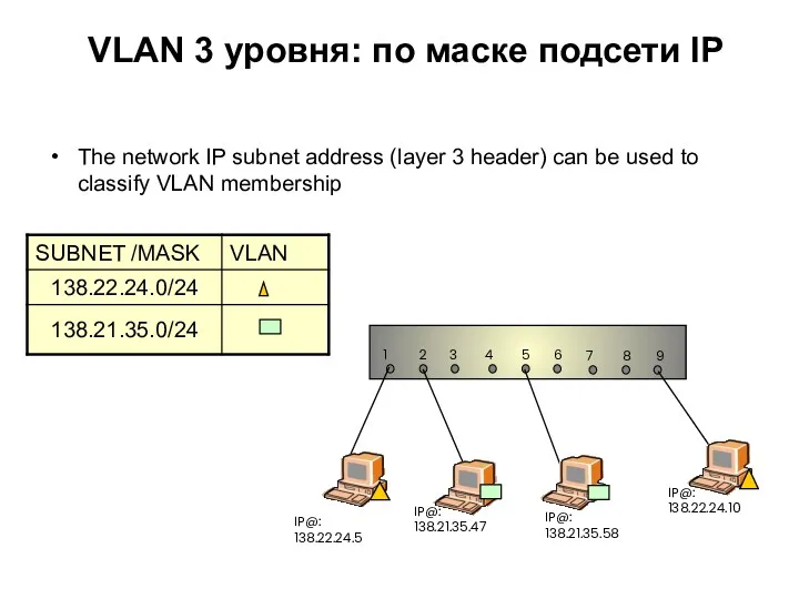
- 36. VLAN 3 уровня: по маске подсети IP The network IP subnet address (layer 3 header) can
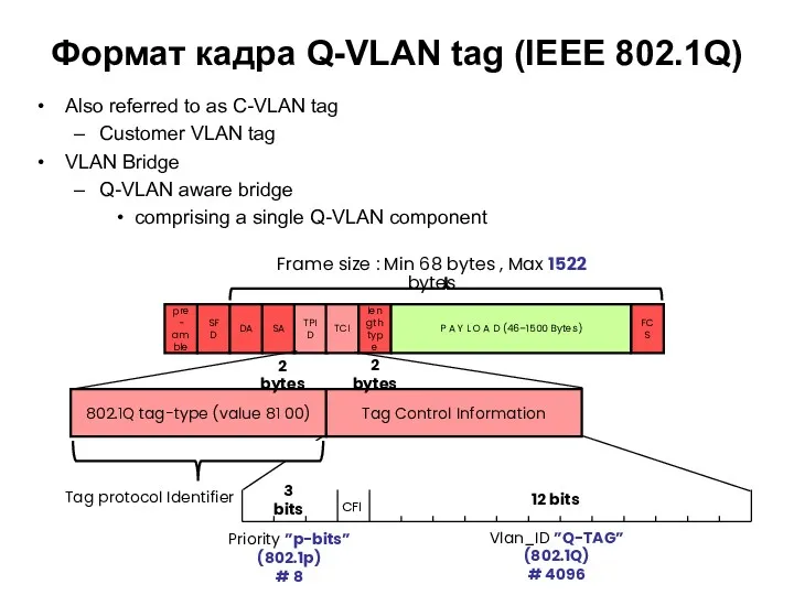
- 37. Формат кадра Q-VLAN tag (IEEE 802.1Q) Also referred to as C-VLAN tag Customer VLAN tag VLAN
- 38. Формат кадра Q-VLAN tag (IEEE 802.1Q) Also referred to as C-VLAN tag Customer VLAN tag VLAN
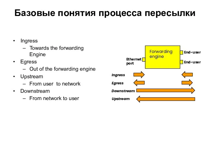
- 39. Базовые понятия процесса пересылки Ingress Towards the forwarding Engine Egress Out of the forwarding engine Upstream
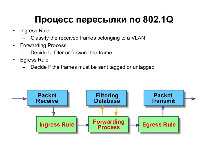
- 40. Процесс пересылки по 802.1Q Ingress Rule Classify the received frames belonging to a VLAN Forwarding Process
- 41. Tagged frame Ingress Rule VID Untagged frame Tagged frame VID Tagged frame PVID Правила входа VLAN-aware
- 42. 3 3 2 Egress Port Static Static Static Register Untag 100 Tag 1 Untag 1 Egress
- 43. Tagged frame Egress Rule VID Untagged frame Tagged frame VID Tagged frame VID Правила выхода
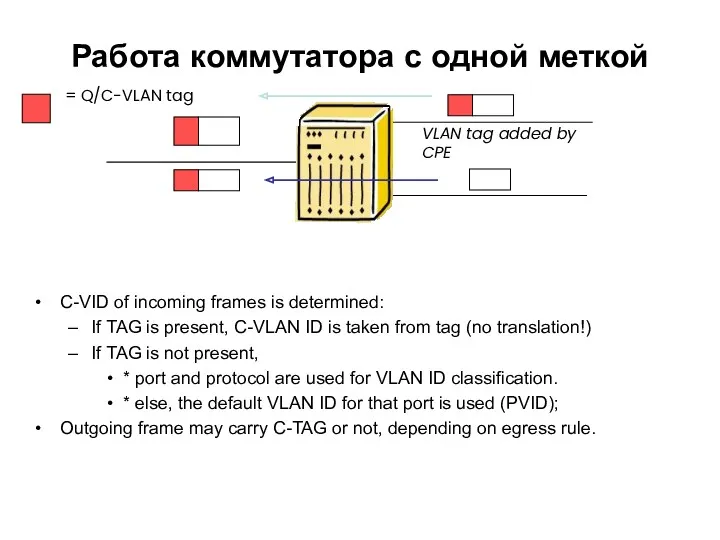
- 44. Работа коммутатора с одной меткой C-VID of incoming frames is determined: If TAG is present, C-VLAN
- 45. Структура коммутатора для стека меток Single VLAN tag: Only 4094 VIDs ⇨ Scalability issue Inroduction of
- 46. Коммутатор провайдерского класса с одной меткой(1) S-VID of incoming frames is defined: If S-TAG is present,
- 47. Коммутатор провайдерского класса с одной меткой(2) An incoming frame on a provider edge port is forwarded
- 48. Стекирование VLAN IEEE 802.1ad Certain vendors apply today 1Q-in-Q VLAN Tag like Alcatel,… SFD pre- amble
- 49. Формат S-метки Q-in-Q VLAN Not standardized The second VLAN tag protocol identifier is 802.1Q tag type
- 50. Коммутатор провайдерского класса с двумя метками We now have two tags The S-TAG may be added
- 51. Структура сети METRO Ethernet Two types of Provider Bridges. - Provider Edge Bridge includes a component
- 52. Сравнительная характеристика LAN и MAN сетей
- 53. Структура Carrier Ethernet
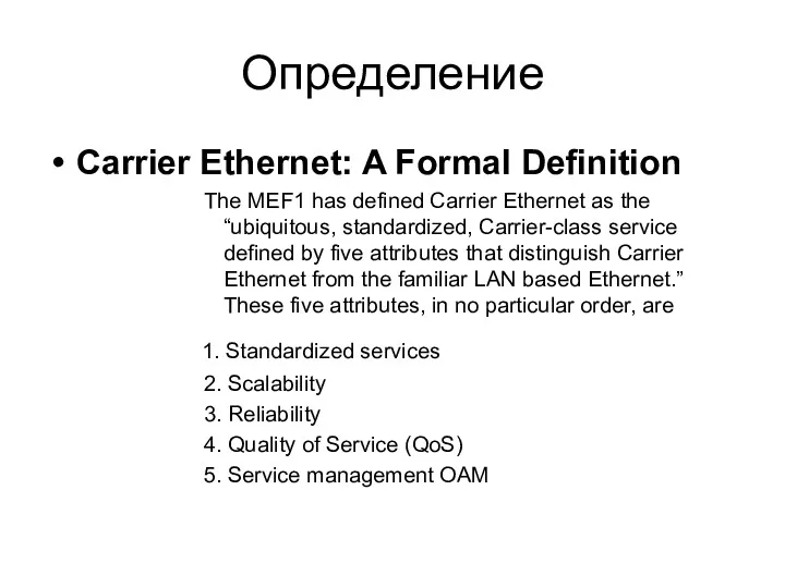
- 54. Определение Carrier Ethernet: A Formal Definition The MEF1 has defined Carrier Ethernet as the “ubiquitous, standardized,
- 55. Стандартизация Carrier Ethernet
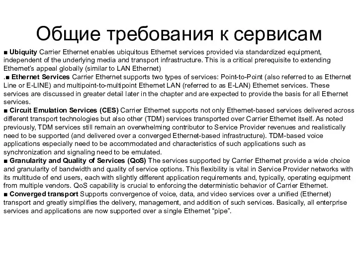
- 56. Общие требования к сервисам ■ Ubiquity Carrier Ethernet enables ubiquitous Ethernet services provided via standardized equipment,
- 57. Модель Ethernet сервисов
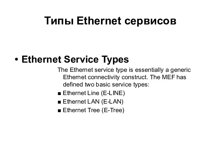
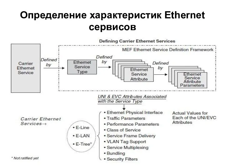
- 58. Типы Ethernet сервисов Ethernet Service Types The Ethernet service type is essentially a generic Ethernet connectivity
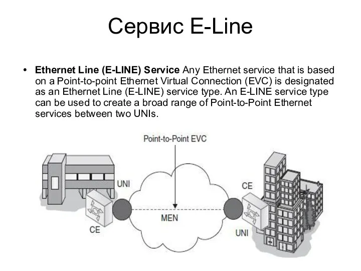
- 59. Сервис E-Line Ethernet Line (E-LINE) Service Any Ethernet service that is based on a Point-to-point Ethernet
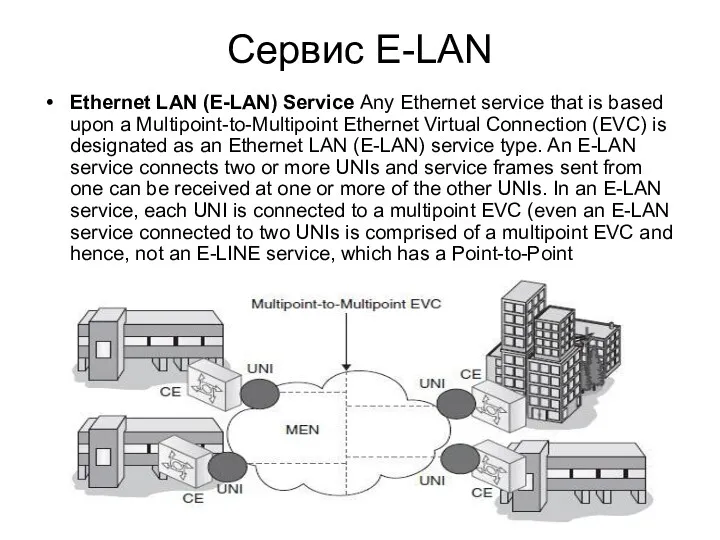
- 60. Сервис E-LAN Ethernet LAN (E-LAN) Service Any Ethernet service that is based upon a Multipoint-to-Multipoint Ethernet
- 61. Определение характеристик Ethernet сервисов
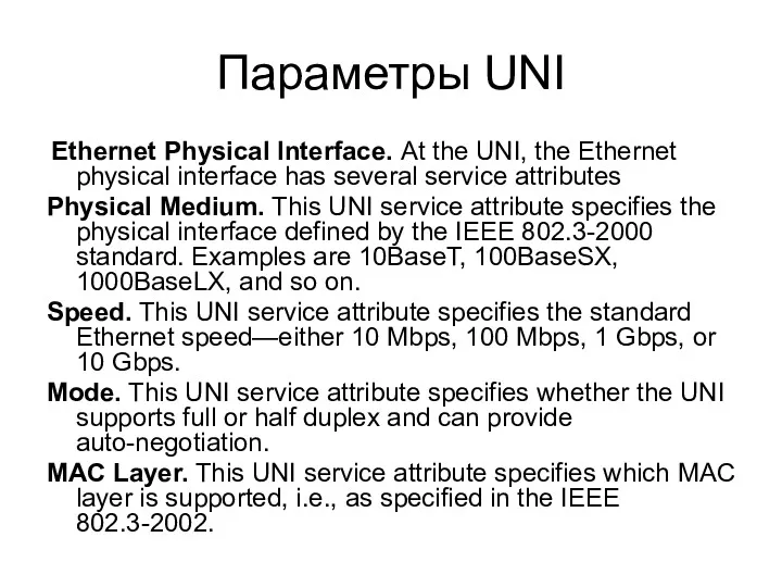
- 62. Параметры UNI Ethernet Physical Interface. At the UNI, the Ethernet physical interface has several service attributes
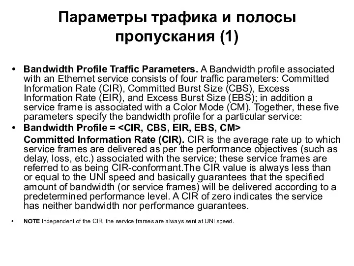
- 63. Параметры трафика и полосы пропускания (1) Bandwidth Profile Traffic Parameters. A Bandwidth profile associated with an
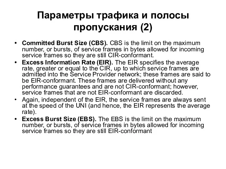
- 64. Параметры трафика и полосы пропускания (2) Committed Burst Size (CBS). CBS is the limit on the
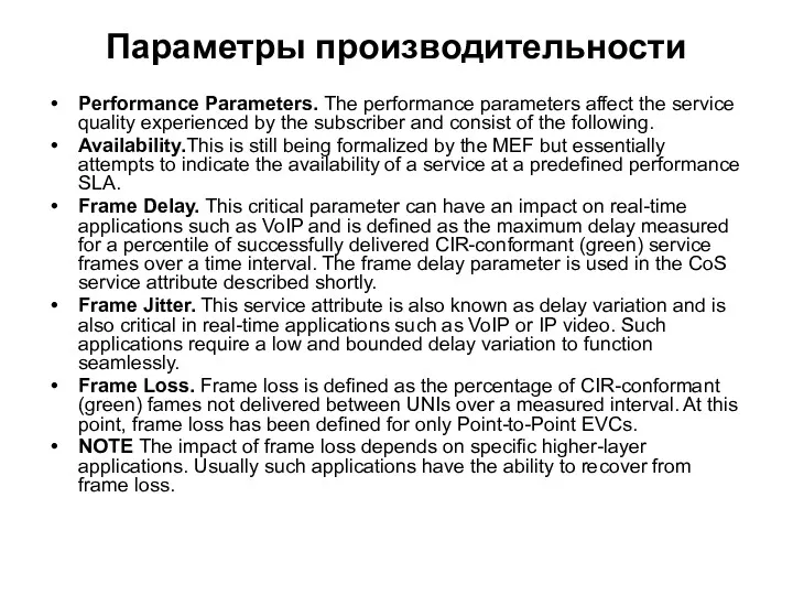
- 65. Параметры производительности Performance Parameters. The performance parameters affect the service quality experienced by the subscriber and
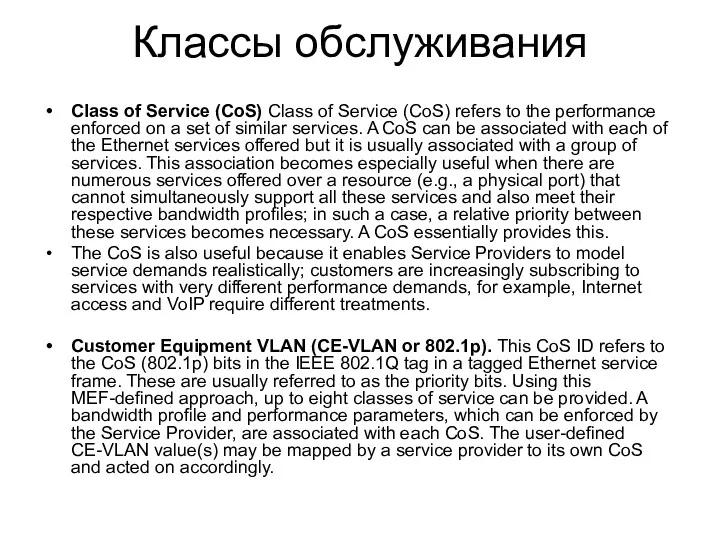
- 66. Классы обслуживания Class of Service (CoS) Class of Service (CoS) refers to the performance enforced on
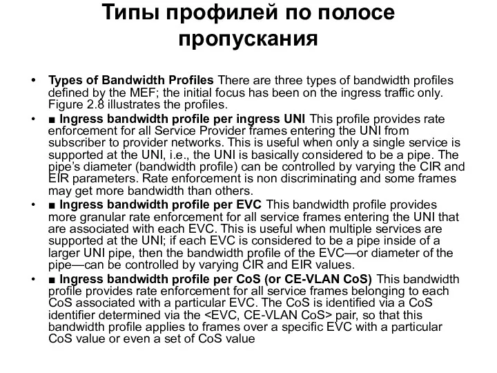
- 67. Типы профилей по полосе пропускания Types of Bandwidth Profiles There are three types of bandwidth profiles
- 68. Уровни профилей по полосе пропускания
- 69. Способы расширения сетей Metro Ethernet SONET/SDH-based Ethernet MANs A SONETA SONET/SDH based Ethernet MAN is usually
- 70. Формат кадра стандарта 802.ah VLAN Frame 802.1ad Q-in-Q Prio/ DE Vers Service Instance ≥20bits The actual
- 72. Скачать презентацию
Содержание
1. Технология Ethernet
2. Виртуальные локальные сети VLAN
3. Технология Carrier Ethernet для
Содержание
1. Технология Ethernet
2. Виртуальные локальные сети VLAN
3. Технология Carrier Ethernet для
Технология Ethernet: уровни BRM OSI
Data Link
Physical
Ethernet
802.2
802.3
Physical (PHY)
Media Access (MAC)
MAC-client (LLC)
Технология Ethernet: уровни BRM OSI
Data Link
Physical
Ethernet
802.2
802.3
Physical (PHY)
Media Access (MAC)
MAC-client (LLC)
Топологии соединений и сетей Ethernet
Star Structure
Bus Structure
Point-to-Point
Structure
Топологии соединений и сетей Ethernet
Star Structure
Bus Structure
Point-to-Point
Structure
Коллизии и их преодоления
Большое количество рабочих станций порождает большое число коллизий
Коллизии и их преодоления
Большое количество рабочих станций порождает большое число коллизий
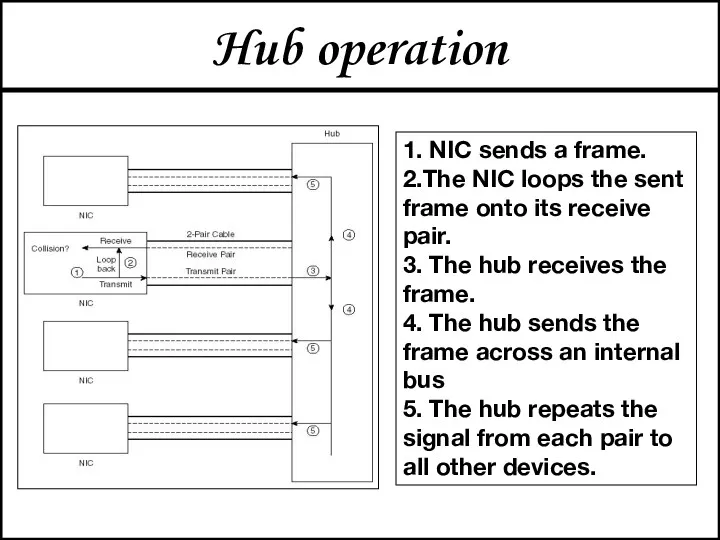
Hub operation
1. NIC sends a frame.
2.The NIC loops the sent frame
Hub operation
1. NIC sends a frame.
2.The NIC loops the sent frame
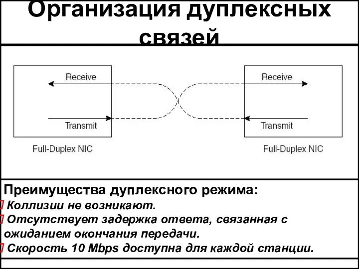
Организация дуплексных связей
Преимущества дуплексного режима:
Коллизии не возникают.
Отсутствует задержка
Организация дуплексных связей
Преимущества дуплексного режима:
Коллизии не возникают.
Отсутствует задержка
Стандарты Ethernet и Fast Ethernet
Стандарты Ethernet и Fast Ethernet
Стандарты Fast Ethernet и Gigabit Ethernet
Стандарты Fast Ethernet и Gigabit Ethernet

Уровень звена данных
Ethernet:
форматы кадров
Уровень звена данных
Ethernet:
форматы кадров
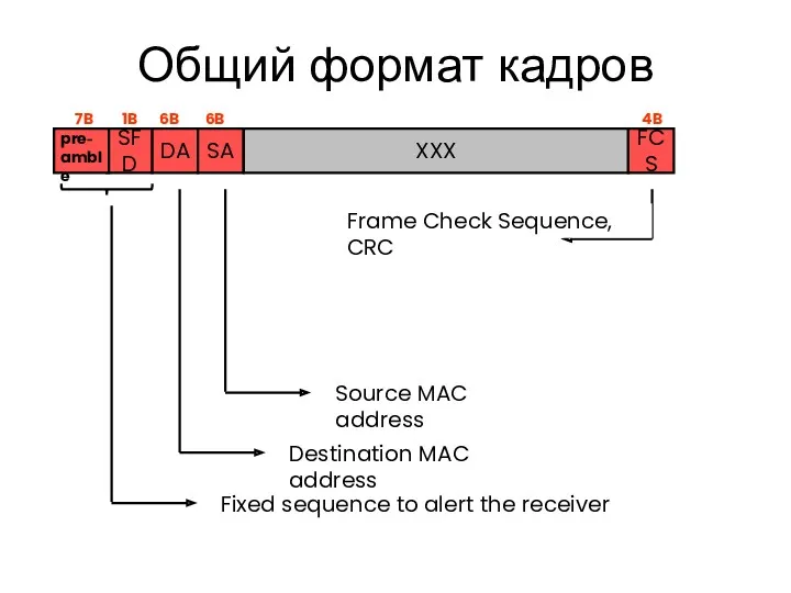
Общий формат кадров
SFD
Fixed sequence to alert the receiver
DA
Destination MAC address
Общий формат кадров
SFD
Fixed sequence to alert the receiver
DA
Destination MAC address
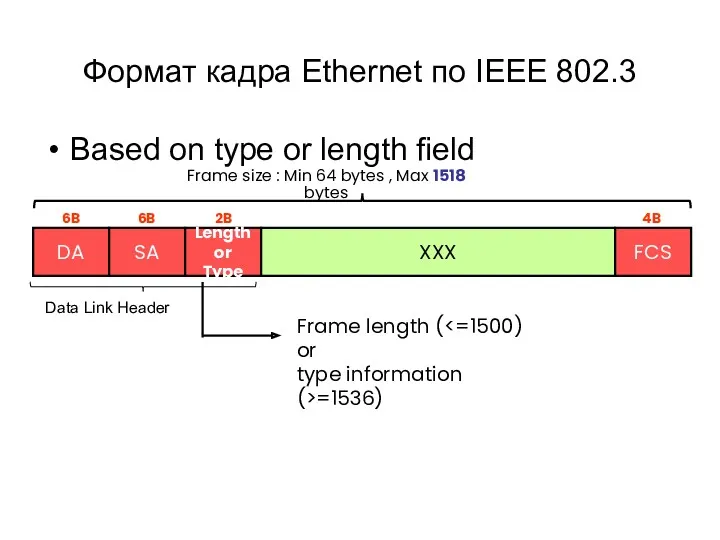
Формат кадра Ethernet по IEEE 802.3
Based on type or length
Формат кадра Ethernet по IEEE 802.3
Based on type or length
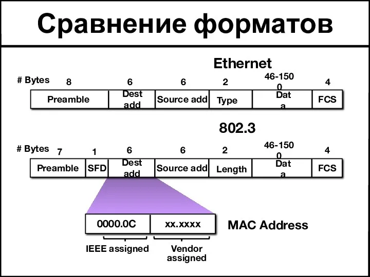
Сравнение форматов
Data
Source add
FCS
Length
Dest add
46-1500
2
6
6
4
0000.0C xx.xxxx
Vendor assigned
IEEE assigned
802.3
Preamble
MAC Address
7
# Bytes
SFD
1
Data
Source add
FCS
Type
Dest add
46-1500
2
6
6
4
Preamble
8
#
Сравнение форматов
Data
Source add
FCS
Length
Dest add
46-1500
2
6
6
4
0000.0C xx.xxxx
Vendor assigned
IEEE assigned
802.3
Preamble
MAC Address
7
# Bytes
SFD
1
Data
Source add
FCS
Type
Dest add
46-1500
2
6
6
4
Preamble
8
#
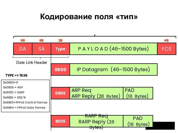
Кодирование поля «тип»
DA
SA
Type
P A Y L O A D (46–1500 Bytes)
0806
ARP
Кодирование поля «тип»
DA
SA
Type
P A Y L O A D (46–1500 Bytes)
0806
ARP
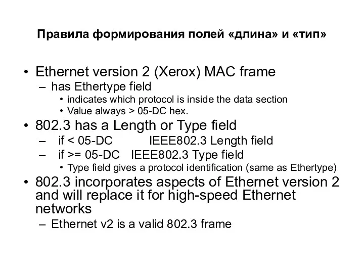
Правила формирования полей «длина» и «тип»
Ethernet version 2 (Xerox) MAC frame
Правила формирования полей «длина» и «тип»
Ethernet version 2 (Xerox) MAC frame
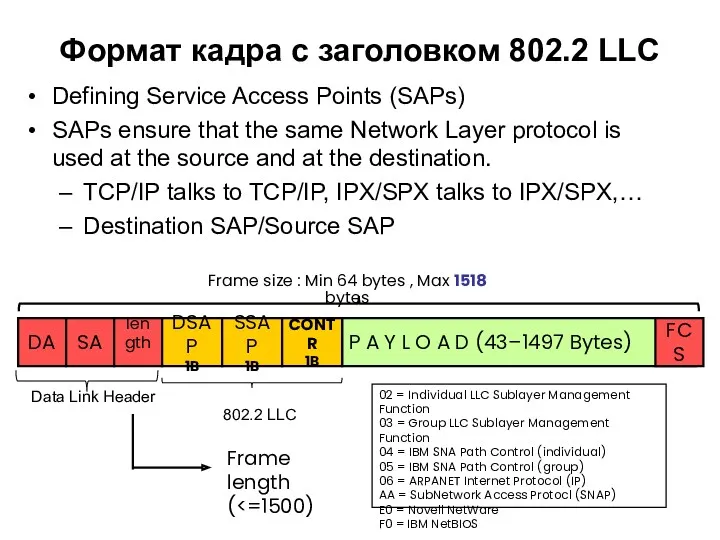
Формат кадра с заголовком 802.2 LLC
Defining Service Access Points (SAPs)
SAPs
Формат кадра с заголовком 802.2 LLC
Defining Service Access Points (SAPs)
SAPs
SNAP
Формат заголовка IIEE 802.3 SNAP
Due to growing number of applications using
SNAP
Формат заголовка IIEE 802.3 SNAP
Due to growing number of applications using
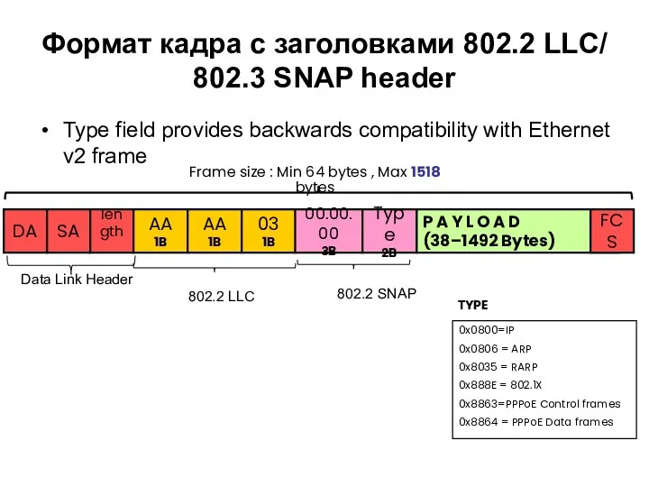
Формат кадра с заголовками 802.2 LLC/ 802.3 SNAP header
Type field provides
Формат кадра с заголовками 802.2 LLC/ 802.3 SNAP header
Type field provides
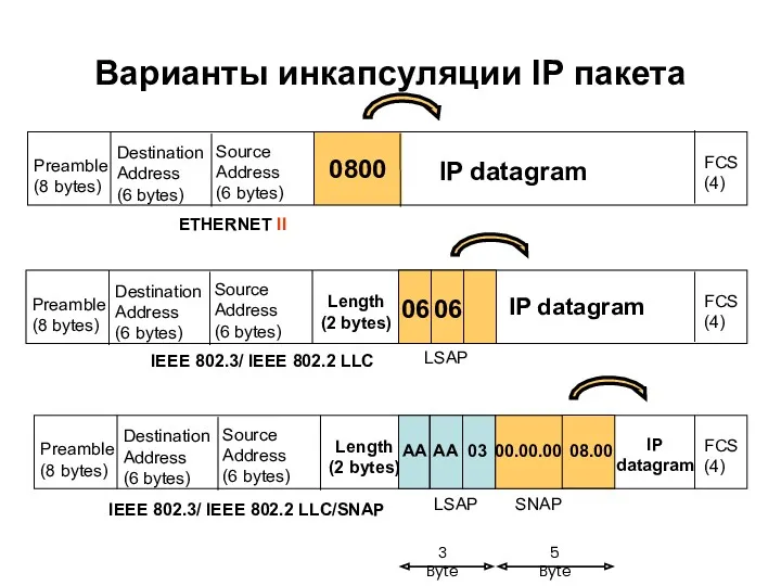
Варианты инкапсуляции IP пакета
0800
IP datagram
Preamble
(8 bytes)
Destination
Address
(6 bytes)
Source
Address
(6 bytes)
FCS
(4)
Варианты инкапсуляции IP пакета
0800
IP datagram
Preamble
(8 bytes)
Destination
Address
(6 bytes)
Source
Address
(6 bytes)
FCS
(4)
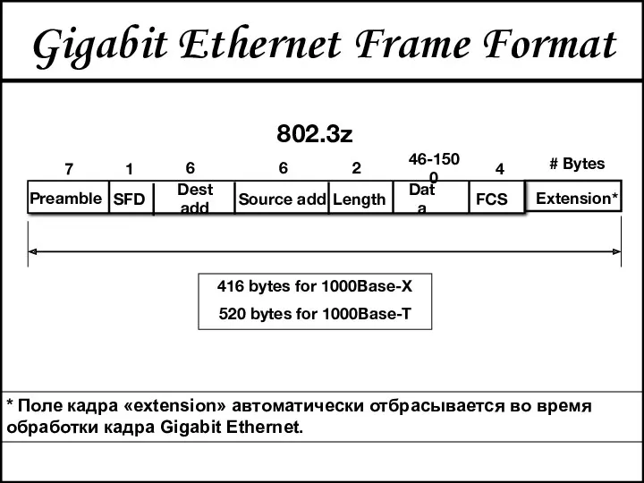
Gigabit Ethernet Frame Format
Data
Source add
FCS
Length
Dest add
46-1500
2
6
6
4
802.3z
Preamble
7
# Bytes
SFD
1
Extension*
416 bytes for 1000Base-X
520 bytes
Gigabit Ethernet Frame Format
Data
Source add
FCS
Length
Dest add
46-1500
2
6
6
4
802.3z
Preamble
7
# Bytes
SFD
1
Extension*
416 bytes for 1000Base-X
520 bytes
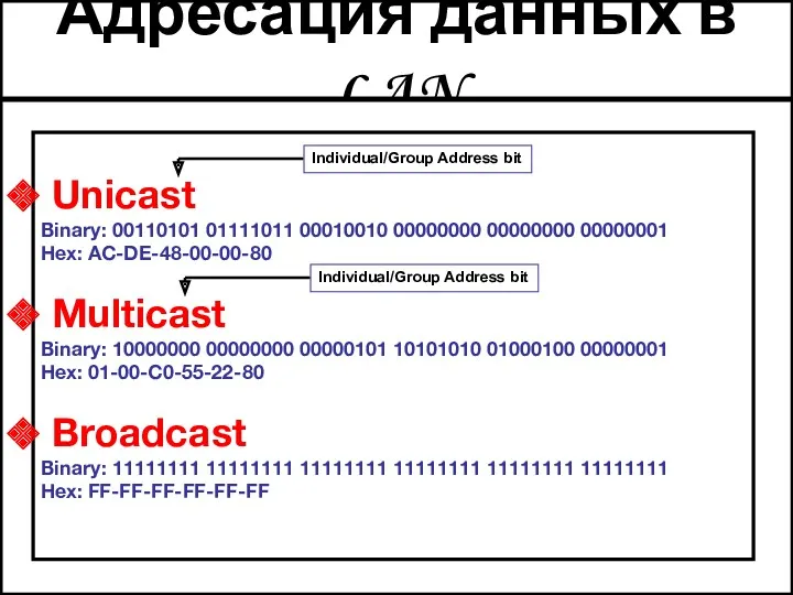
Адресация данных в LAN
Unicast
Binary: 00110101 01111011 00010010 00000000 00000000
Адресация данных в LAN
Unicast
Binary: 00110101 01111011 00010010 00000000 00000000
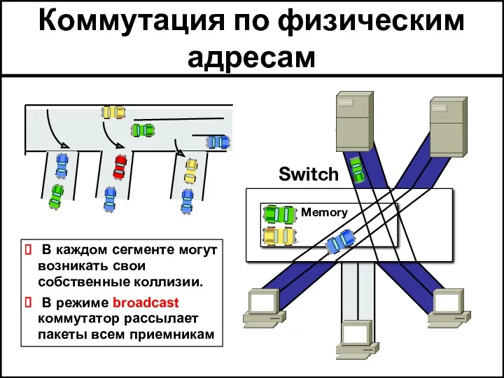
Коммутация по физическим адресам
В каждом сегменте могут возникать свои собственные
Коммутация по физическим адресам
В каждом сегменте могут возникать свои собственные
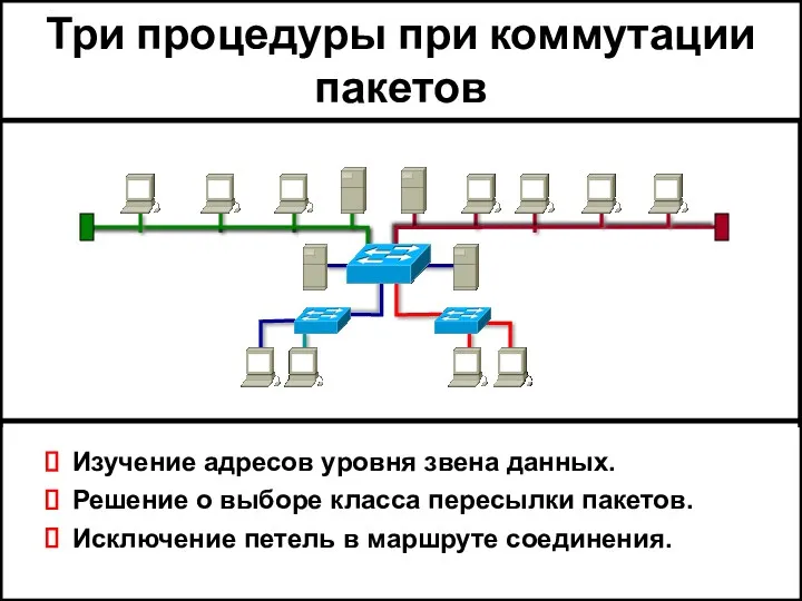
Три процедуры при коммутации пакетов
Изучение адресов уровня звена данных.
Решение о выборе
Три процедуры при коммутации пакетов
Изучение адресов уровня звена данных.
Решение о выборе
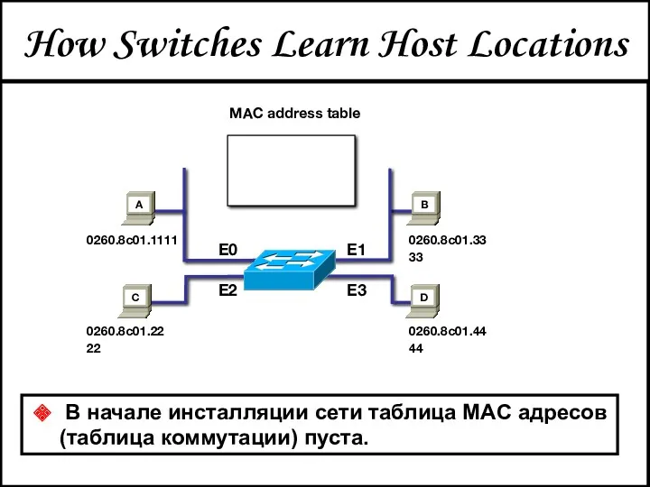
How Switches Learn Host Locations
В начале инсталляции сети таблица MAC
How Switches Learn Host Locations
В начале инсталляции сети таблица MAC
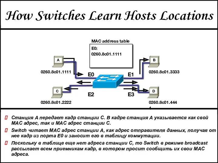
How Switches Learn Hosts Locations
Станция A передает кадр станции C. В
How Switches Learn Hosts Locations
Станция A передает кадр станции C. В
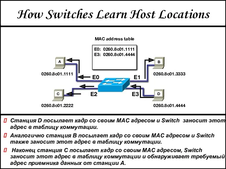
How Switches Learn Host Locations
Станция D посылает кадр со своим MAC
How Switches Learn Host Locations
Станция D посылает кадр со своим MAC
How Switches Filter Frames
Switch пересылает кадр, полученный от станции A из
How Switches Filter Frames
Switch пересылает кадр, полученный от станции A из
Broadcast and Multicast Frames
Станция D передает кадр в режиме broadcast, или
Broadcast and Multicast Frames
Станция D передает кадр в режиме broadcast, или
Ethernet: организация
виртуальных
локальных сетей
(VLAN)
Ethernet: организация
виртуальных
локальных сетей
(VLAN)
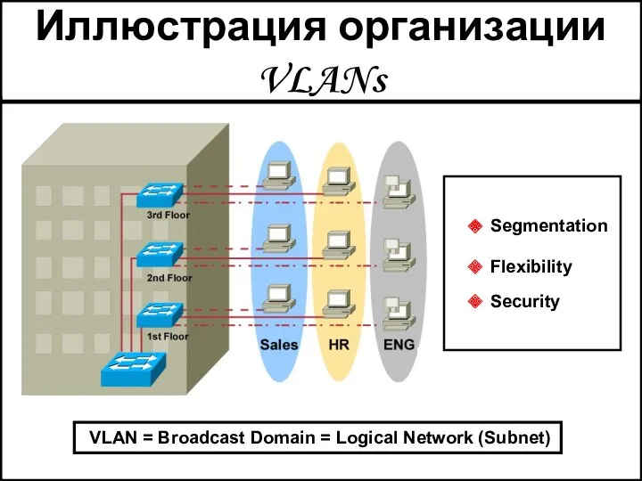
VLAN = Broadcast Domain = Logical Network (Subnet)
Иллюстрация организации
VLAN = Broadcast Domain = Logical Network (Subnet)
Иллюстрация организации
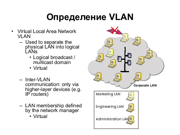
Определение VLAN
Virtual Local Area Network
VLAN
Used to separate the physical LAN
Определение VLAN
Virtual Local Area Network
VLAN
Used to separate the physical LAN
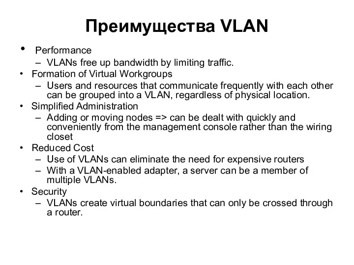
Преимущества VLAN
Performance
VLANs free up bandwidth by limiting traffic.
Formation of Virtual
Преимущества VLAN
Performance
VLANs free up bandwidth by limiting traffic.
Formation of Virtual
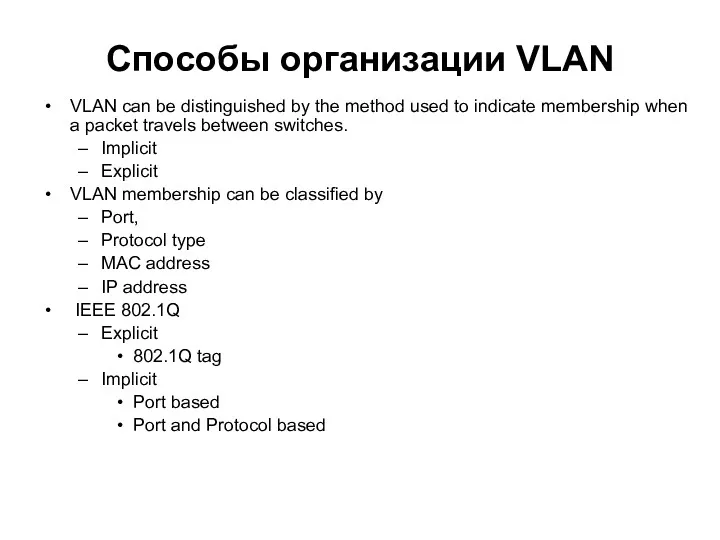
Способы организации VLAN
VLAN can be distinguished by the method used to
Способы организации VLAN
VLAN can be distinguished by the method used to
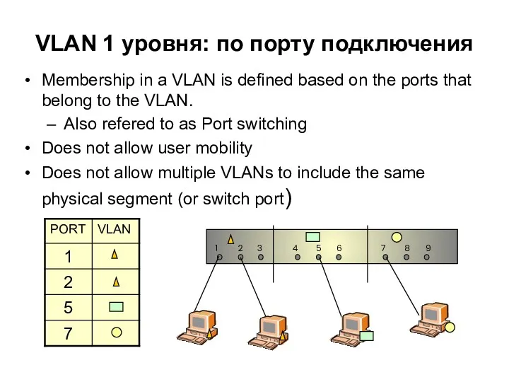
VLAN 1 уровня: по порту подключения
Membership in a VLAN is defined
VLAN 1 уровня: по порту подключения
Membership in a VLAN is defined
VLAN 2 уровня: по MACадресу
Membership in a VLAN is based
VLAN 2 уровня: по MACадресу
Membership in a VLAN is based
VLAN 3 уровня: по маске подсети IP
The network IP
VLAN 3 уровня: по маске подсети IP
The network IP
Формат кадра Q-VLAN tag (IEEE 802.1Q)
Also referred to as C-VLAN tag
Customer
Формат кадра Q-VLAN tag (IEEE 802.1Q)
Also referred to as C-VLAN tag
Customer

Формат кадра Q-VLAN tag (IEEE 802.1Q)
Also referred to as C-VLAN tag
Customer
Формат кадра Q-VLAN tag (IEEE 802.1Q)
Also referred to as C-VLAN tag
Customer
Базовые понятия процесса пересылки
Ingress
Towards the forwarding Engine
Egress
Out of the forwarding engine
Базовые понятия процесса пересылки
Ingress
Towards the forwarding Engine
Egress
Out of the forwarding engine
Процесс пересылки по 802.1Q
Ingress Rule
Classify the received frames belonging
Процесс пересылки по 802.1Q
Ingress Rule
Classify the received frames belonging
Tagged frame
Ingress Rule
VID
Untagged frame
Tagged frame
VID
Tagged frame
PVID
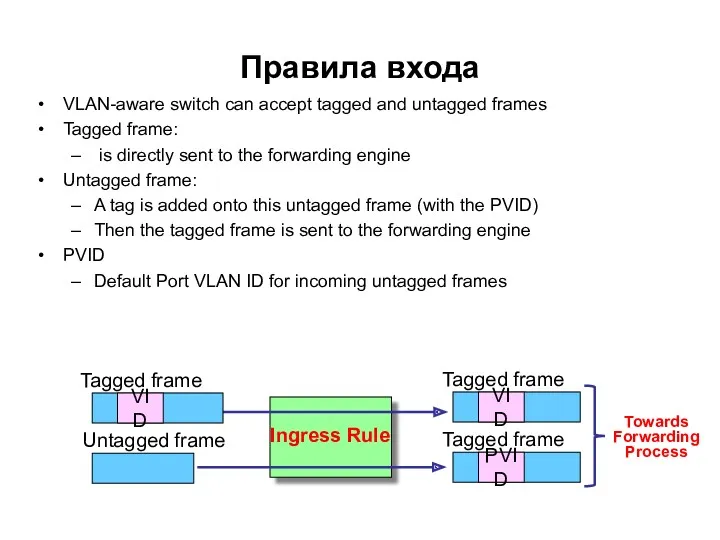
Правила входа
VLAN-aware switch can accept tagged
Tagged frame
Ingress Rule
VID
Untagged frame
Tagged frame
VID
Tagged frame
PVID
Правила входа
VLAN-aware switch can accept tagged
3
3
2
Egress
Port
Static
Static
Static
Register
Untag
100
Tag
1
Untag
1
Egress frame type
VID
10
3
2
2
Port
30
00:A0:C5:33:33:33
100
00:A0:C5:44:44:44
20
00:A0:C5:22:22:22
0
00:A0:C5:11:11:11
Aging
MAC Address
MAC Table
VLAN Table
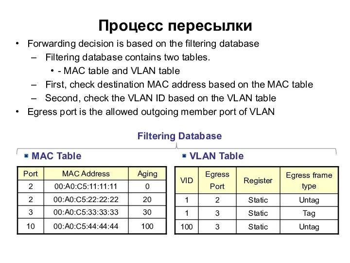
Процесс пересылки
Forwarding decision is
3
3
2
Egress
Port
Static
Static
Static
Register
Untag
100
Tag
1
Untag
1
Egress frame type
VID
10
3
2
2
Port
30
00:A0:C5:33:33:33
100
00:A0:C5:44:44:44
20
00:A0:C5:22:22:22
0
00:A0:C5:11:11:11
Aging
MAC Address
MAC Table
VLAN Table
Процесс пересылки
Forwarding decision is
Tagged frame
Egress Rule
VID
Untagged frame
Tagged frame
VID
Tagged frame
VID
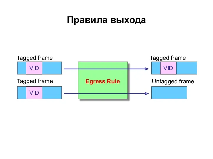
Правила выхода
Tagged frame
Egress Rule
VID
Untagged frame
Tagged frame
VID
Tagged frame
VID
Правила выхода
Работа коммутатора с одной меткой
C-VID of incoming frames is determined:
If TAG
Работа коммутатора с одной меткой
C-VID of incoming frames is determined:
If TAG
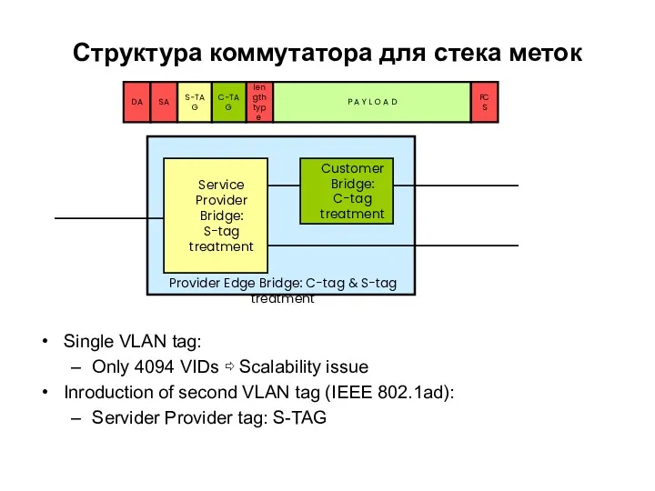
Структура коммутатора для стека меток
Single VLAN tag:
Only 4094 VIDs ⇨ Scalability
Структура коммутатора для стека меток
Single VLAN tag:
Only 4094 VIDs ⇨ Scalability
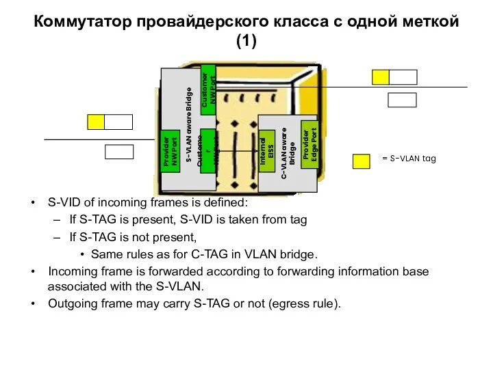
Коммутатор провайдерского класса с одной меткой(1)
S-VID of incoming frames is defined:
If
Коммутатор провайдерского класса с одной меткой(1)
S-VID of incoming frames is defined:
If
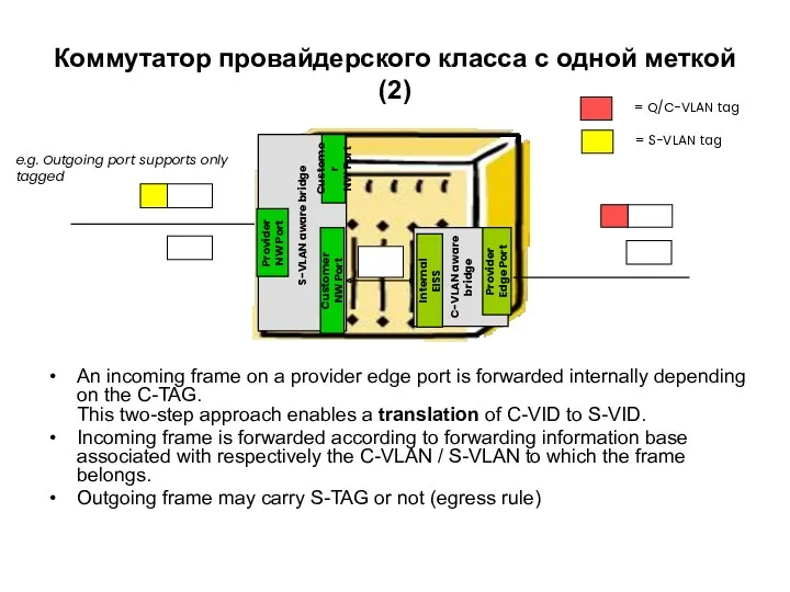
Коммутатор провайдерского класса с одной меткой(2)
An incoming frame on a provider
Коммутатор провайдерского класса с одной меткой(2)
An incoming frame on a provider
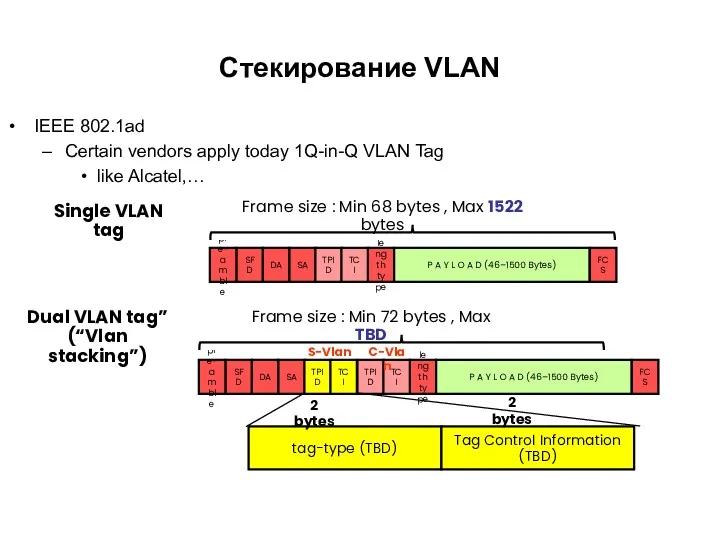
Стекирование VLAN
IEEE 802.1ad
Certain vendors apply today 1Q-in-Q VLAN Tag
like Alcatel,…
SFD
pre-
amble
DA
SA
length
type
P
Стекирование VLAN
IEEE 802.1ad
Certain vendors apply today 1Q-in-Q VLAN Tag
like Alcatel,…
SFD
pre-
amble
DA
SA
length
type
P
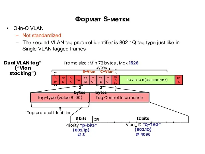
Формат S-метки
Q-in-Q VLAN
Not standardized
The second VLAN tag protocol identifier is
Формат S-метки
Q-in-Q VLAN
Not standardized
The second VLAN tag protocol identifier is
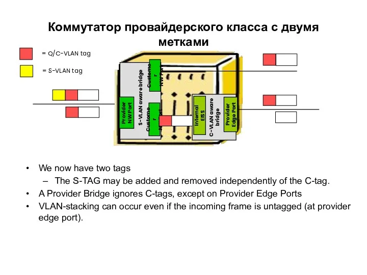
Коммутатор провайдерского класса с двумя метками
We now have two tags
The S-TAG
Коммутатор провайдерского класса с двумя метками
We now have two tags
The S-TAG
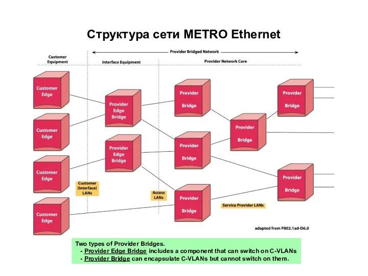
Структура сети METRO Ethernet
Two types of Provider Bridges.
- Provider Edge
Структура сети METRO Ethernet
Two types of Provider Bridges.
- Provider Edge
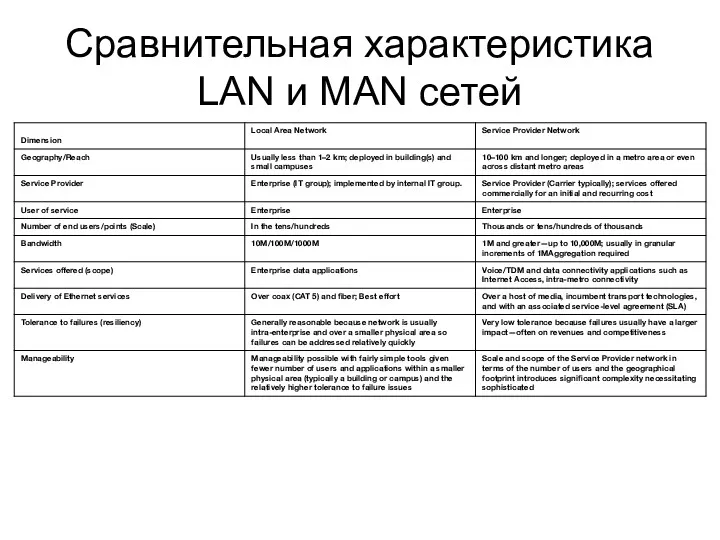
Сравнительная характеристика LAN и MAN сетей
Сравнительная характеристика LAN и MAN сетей
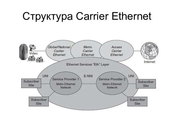
Структура Carrier Ethernet
Структура Carrier Ethernet
Определение
Carrier Ethernet: A Formal Definition
The MEF1 has defined Carrier Ethernet as
Определение
Carrier Ethernet: A Formal Definition
The MEF1 has defined Carrier Ethernet as
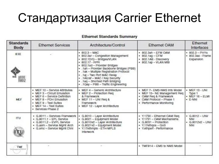
Стандартизация Carrier Ethernet
Стандартизация Carrier Ethernet
Общие требования к сервисам
■ Ubiquity Carrier Ethernet enables ubiquitous Ethernet services
Общие требования к сервисам
■ Ubiquity Carrier Ethernet enables ubiquitous Ethernet services
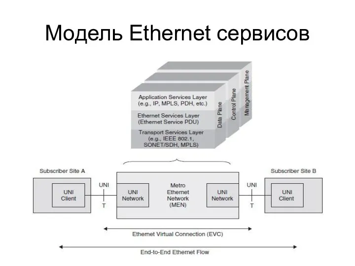
Модель Ethernet сервисов
Модель Ethernet сервисов
Типы Ethernet сервисов
Ethernet Service Types
The Ethernet service type is essentially a
Типы Ethernet сервисов
Ethernet Service Types
The Ethernet service type is essentially a
Сервис E-Line
Ethernet Line (E-LINE) Service Any Ethernet service that is based
Сервис E-Line
Ethernet Line (E-LINE) Service Any Ethernet service that is based
Сервис E-LAN
Ethernet LAN (E-LAN) Service Any Ethernet service that is based
Сервис E-LAN
Ethernet LAN (E-LAN) Service Any Ethernet service that is based
Определение характеристик Ethernet сервисов
Определение характеристик Ethernet сервисов
Параметры UNI
Ethernet Physical Interface. At the UNI, the Ethernet physical
Параметры UNI
Ethernet Physical Interface. At the UNI, the Ethernet physical
Параметры трафика и полосы пропускания (1)
Bandwidth Profile Traffic Parameters. A Bandwidth
Параметры трафика и полосы пропускания (1)
Bandwidth Profile Traffic Parameters. A Bandwidth
Параметры трафика и полосы пропускания (2)
Committed Burst Size (CBS). CBS is
Параметры трафика и полосы пропускания (2)
Committed Burst Size (CBS). CBS is
Параметры производительности
Performance Parameters. The performance parameters affect the service quality experienced
Параметры производительности
Performance Parameters. The performance parameters affect the service quality experienced
Классы обслуживания
Class of Service (CoS) Class of Service (CoS) refers to
Классы обслуживания
Class of Service (CoS) Class of Service (CoS) refers to
Типы профилей по полосе пропускания
Types of Bandwidth Profiles There are three
Типы профилей по полосе пропускания
Types of Bandwidth Profiles There are three
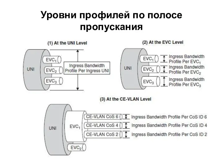
Уровни профилей по полосе пропускания
Уровни профилей по полосе пропускания
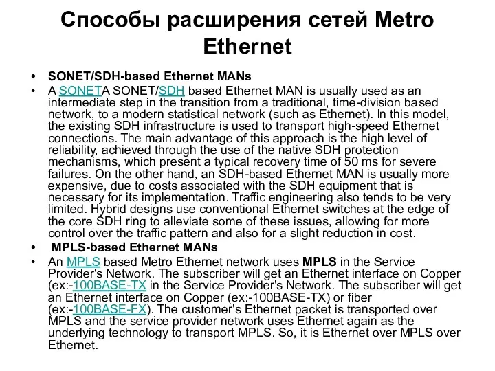
Способы расширения сетей Metro Ethernet
SONET/SDH-based Ethernet MANs
A SONETA SONET/SDH based Ethernet
Способы расширения сетей Metro Ethernet
SONET/SDH-based Ethernet MANs
A SONETA SONET/SDH based Ethernet
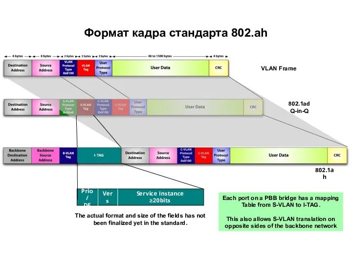
Формат кадра стандарта 802.ah
VLAN Frame
802.1ad
Q-in-Q
Prio/
DE
Vers
Service Instance ≥20bits
The actual format and size
Формат кадра стандарта 802.ah
VLAN Frame
802.1ad
Q-in-Q
Prio/
DE
Vers
Service Instance ≥20bits
The actual format and size
 Языки программирования
 Понятие алгоритма, свойства, виды (типы). Формы записи. Исходные и выходные данные алгоритмов, примеры (Лекция 3)
 Тип String (java)
 Використання вбудованих функцій в табличному процесорі MS Excel
 Варианты использования. Диаграммы прецедентов. Практическое освоение методологии моделирования
 “Кодирование текстовой информации”
 Как вставить презентацию на страницу блога.pptx
 Анализ методов перехвата паролей и методов противодействия им
 Работа с массивами в C#
 Файлы и файловая система. Программное обеспечение
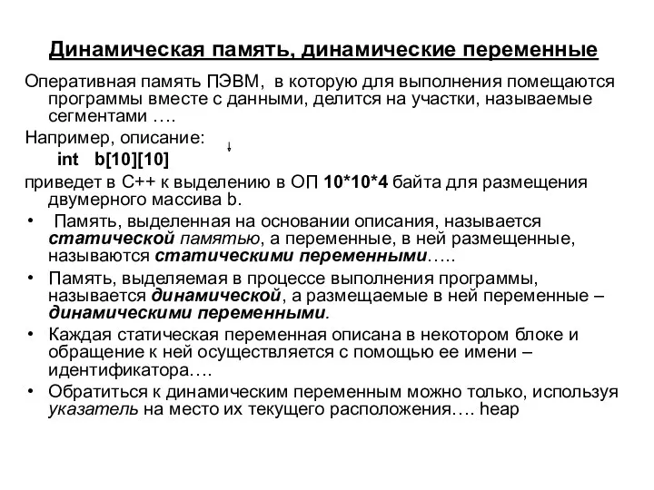 Динамическая память, динамические переменные
 Основные направления развития современных технологий искусственного интеллекта
 Hackers
 QOS Requirements and Service Level Agreements. VPN Hose and Pipe Models. Per Flow Sequence Preservation
 Картографическое сопровождение поиска
 IT-профессия программист
 Разработка чат-бота для абитуриентов ВУЗа
 Inter-Process Communication (IPC). Межпроцессное взаимодействие
 Вычисление суммы. Вычисление элементов последовательности
 Системи числення
 История развития вычислительной техники
 Устройства ввода-вывода
 Информационные технологии в профессиональной деятельности
 Коммуникативная компетентность пользователей сети интерне
 Структура окна программы AutoCad
 Тестирование информационной системы
 Параллельное программирование с использованием технологии MPI
 Константность. Конструктор копирования. Класс массива. ООП. Лекция 5