QOS Requirements and Service Level Agreements. VPN Hose and Pipe Models. Per Flow Sequence Preservation презентация
- QOS Requirements and Service Level Agreements. VPN Hose and Pipe Models. Per Flow Sequence Preservation

Содержание
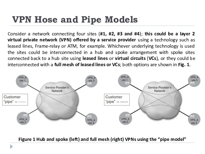
- 2. VPN Hose and Pipe Models Consider a network connecting four sites (#1, #2, #3 and #4);
- 3. VPN Hose and Pipe Models In both cases shown in Figure 1, each leased line or
- 4. VPN Hose and Pipe Models VPNs built using IP or MPLS technology, e.g. BGP MPLS VPNs
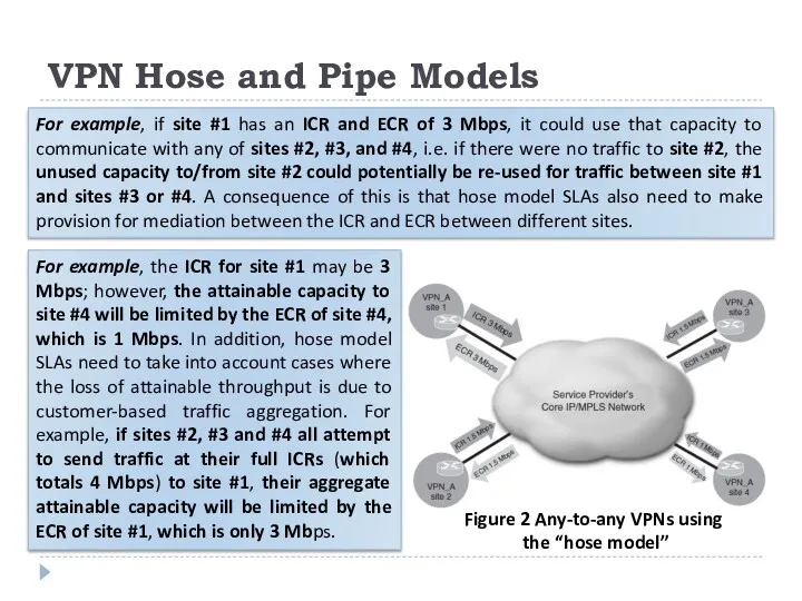
- 5. VPN Hose and Pipe Models Figure 2 Any-to-any VPNs using the “hose model” For example, if
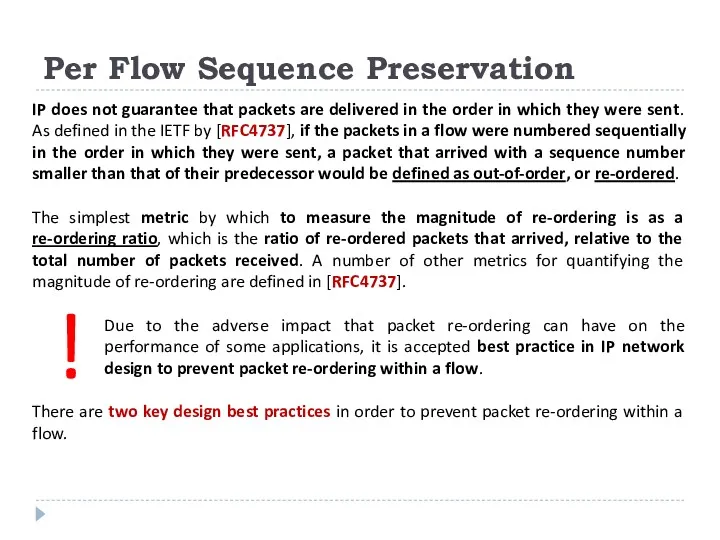
- 6. Per Flow Sequence Preservation IP does not guarantee that packets are delivered in the order in
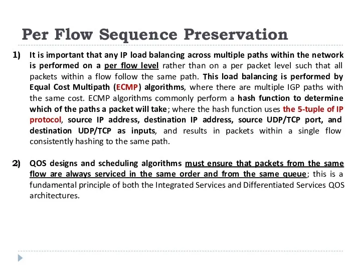
- 7. Per Flow Sequence Preservation It is important that any IP load balancing across multiple paths within
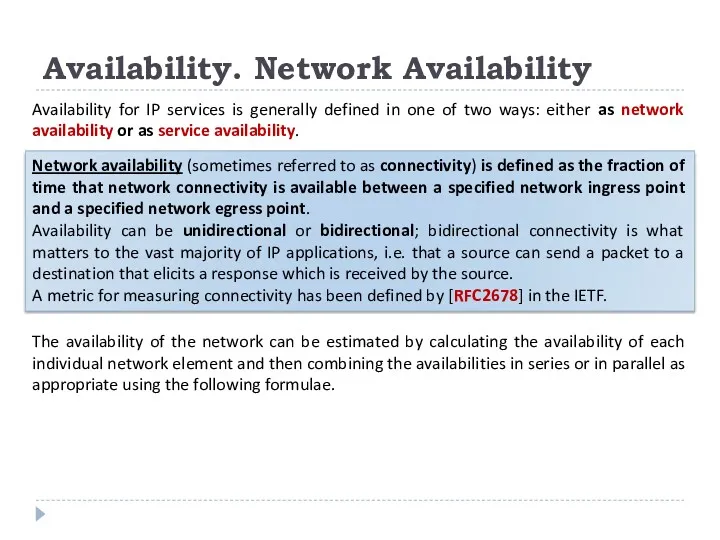
- 8. Availability. Network Availability Availability for IP services is generally defined in one of two ways: either
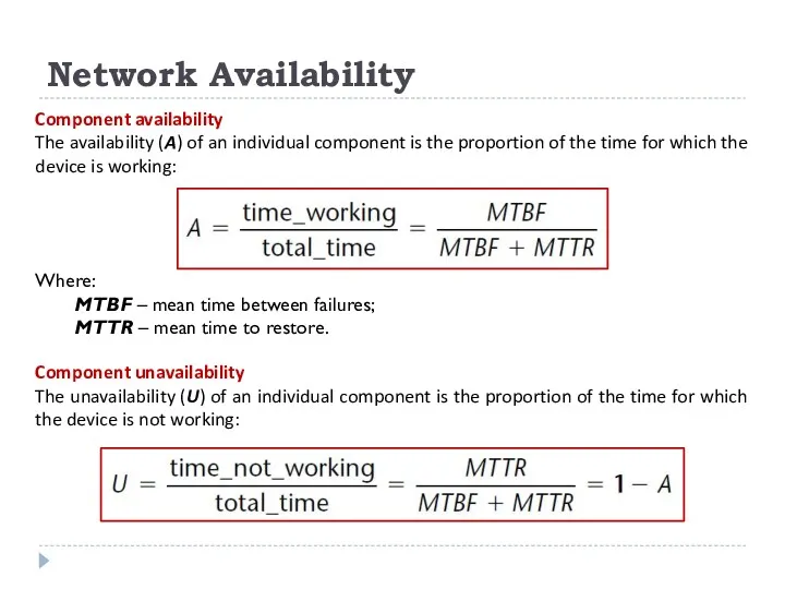
- 9. Network Availability Component availability The availability (A) of an individual component is the proportion of the
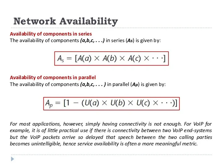
- 10. Network Availability Availability of components in series The availability of components (a,b,c, . . .) in
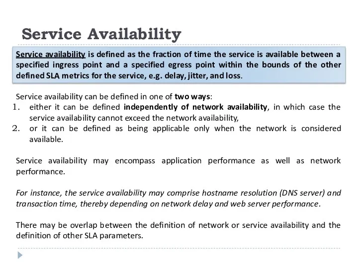
- 11. Service Availability Service availability is defined as the fraction of time the service is available between
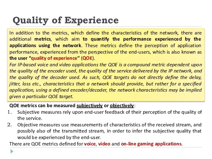
- 12. Quality of Experience QOE metrics can be measured subjectively or objectively: Subjective measures rely upon end-user
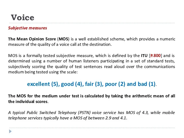
- 13. Voice Subjective measures The Mean Opinion Score (MOS) is a well established scheme, which provides a
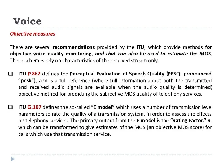
- 14. Voice Objective measures There are several recommendations provided by the ITU, which provide methods for objective
- 16. Скачать презентацию
VPN Hose and Pipe Models
Consider a network connecting four sites (#1,
VPN Hose and Pipe Models
Consider a network connecting four sites (#1,
VPN Hose and Pipe Models
In both cases shown in Figure 1,
VPN Hose and Pipe Models
In both cases shown in Figure 1,
VPN Hose and Pipe Models
VPNs built using IP or MPLS technology,
VPN Hose and Pipe Models
VPNs built using IP or MPLS technology,
VPN Hose and Pipe Models
Figure 2 Any-to-any VPNs using
the “hose
VPN Hose and Pipe Models
Figure 2 Any-to-any VPNs using
the “hose
Per Flow Sequence Preservation
IP does not guarantee that packets are delivered
Per Flow Sequence Preservation
IP does not guarantee that packets are delivered
Per Flow Sequence Preservation
It is important that any IP load balancing
Per Flow Sequence Preservation
It is important that any IP load balancing
Availability. Network Availability
Availability for IP services is generally defined in one
Availability. Network Availability
Availability for IP services is generally defined in one
Network Availability
Component availability
The availability (A) of an individual component is the
Network Availability
Component availability
The availability (A) of an individual component is the
Network Availability
Availability of components in series
The availability of components (a,b,c, .
Network Availability
Availability of components in series
The availability of components (a,b,c, .
Service Availability
Service availability is defined as the fraction of time the
Service Availability
Service availability is defined as the fraction of time the
Quality of Experience
QOE metrics can be measured subjectively or objectively:
Subjective measures
Quality of Experience
QOE metrics can be measured subjectively or objectively:
Subjective measures
Voice
Subjective measures
The Mean Opinion Score (MOS) is a well established scheme,
Voice
Subjective measures
The Mean Opinion Score (MOS) is a well established scheme,
Voice
Objective measures
There are several recommendations provided by the ITU, which provide
Voice
Objective measures
There are several recommendations provided by the ITU, which provide
 Инструкция по работе с мобильным приложением E-Salyq Azamat в части подачи ФНО 250.00
 Регистрация заявок IT
 Основные компоненты компьютера и их функции
 Внешние международные информационные ресурсы
 Правовое регулирование в информационной сфере
 Сбор и подготовка данных
 Файлы. Работа с файлами
 Сайт научного проекта
 Электронные таблицы Excel
 Программа курса “Введение в тестирование ПО”
 Лекция 11. Планирование и диспетчеризация процессора
 Защищенные мультисервисные телекоммуникационные системы
 Структура HTML
 Защита медицинской информации
 Визуальные алгоритмы SLAM
 Компьютерные сети
 Нормоконтроль. Стандарт организации
 Создание Web-сайта
 Основы программирования. Лекция № 3
 Web Application Penetration Testing
 Как установить книги
 Медиа-карта Региона. Радио СМИ
 Interaction of traditional media and Internet: new media relations
 Пути изучения английского языка с помощью сети интернет
 Как установить программу ZOOM на компьютер
 База данных. Библиотека
 АКТ-ны пайдалану- құзыреттілікті дамыту
 MobileTrans. Поддержка 3000 + телефонов и различных сетей