- What’s New in SolidCAM 2020

Содержание
- 2. 2.5D Milling What’s New in SolidCAM 2020
- 3. Hole Wizard Process – Drag to Surface Finds all holes, perpendicular to the surface, that are
- 4. Full Syncronization in Hole Wizard Process Changing hole type or size will automatically change the tools
- 5. Face Milling Operation – Floor Finish Only You can now use Floor finish only to apply
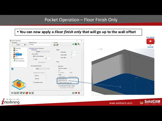
- 6. Pocket Operation – Floor Finish Only You can now apply a Floor finish only that will
- 7. Pocket Operation – Wall and Floor Finish Only You can now apply a Wall and Floor
- 8. Chamfer Recognition – Conventional Direction Enabled You now have the option of Conventional cutting direction Conventional
- 9. New holes Drill Geometry – Improved Synchronization with Multi-positions Adding or removing holes from a face
- 10. Pocket Operation – Open Edge Negative Offset Modify Geometry now supports negative offset values on open
- 11. Profile Operation – Syncronized Link by Points Lead in/out with points are now fully associative The
- 12. iMachining What’s New in SolidCAM 2020
- 13. 3D Positioning in iMachining 2D iMachining 2D can now perform 3D in-pocket positioning like iMachining 3D
- 14. 3D Positioning Comparison – Tool Path Results 3D Positioning Off 3D Positioning On
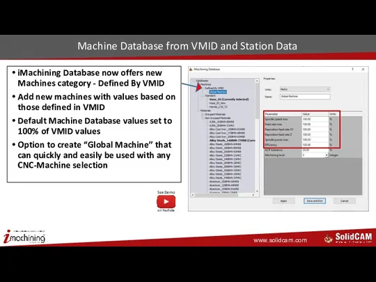
- 15. Machine Database from VMID and Station Data iMachining Database now offers new Machines category - Defined
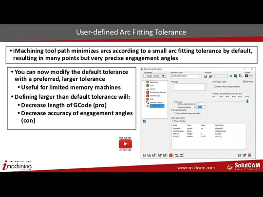
- 16. User-defined Arc Fitting Tolerance iMachining tool path minimizes arcs according to a small arc fitting tolerance
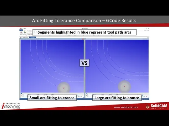
- 17. Arc Fitting Tolerance Comparison – GCode Results Small arc fitting tolerance Large arc fitting tolerance VS
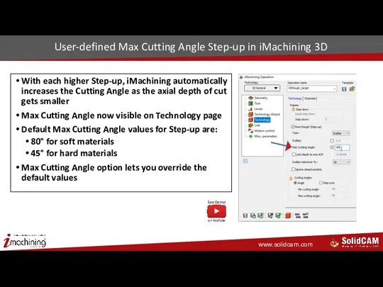
- 18. User-defined Max Cutting Angle Step-up in iMachining 3D With each higher Step-up, iMachining automatically increases the
- 19. HSR/HSM What’s New in SolidCAM 2020
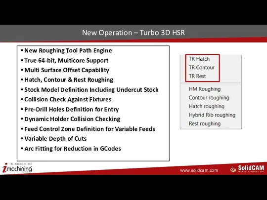
- 20. New Operation – Turbo 3D HSR New Roughing Tool Path Engine True 64-bit, Multicore Support Multi
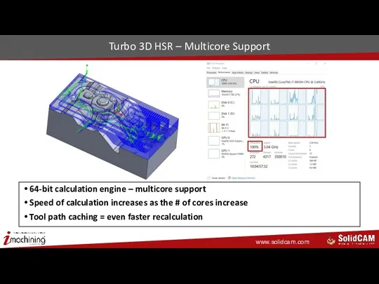
- 21. Turbo 3D HSR – Multicore Support 64-bit calculation engine – multicore support Speed of calculation increases
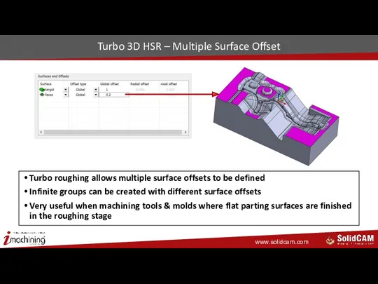
- 22. Turbo 3D HSR – Multiple Surface Offset Turbo roughing allows multiple surface offsets to be defined
- 23. Turbo 3D HSR – Strategies Different machining patterns available Hatch, Contour and Rest roughing
- 24. Turbo 3D HSR – Rest Roughing Rest roughing in Turbo 3D HSR Based on either Updated
- 25. Turbo 3D HSR – Local Stock Definition Stock definition including undercut stock definition Local Stock can
- 26. Turbo 3D HSR – Fixture Collision Protection Collision checking against fixtures using either Faces or Curves
- 27. Turbo 3D HSR – Pre-drilled Points Pre-drilled holes can be defined for tool entry; depth of
- 28. Turbo 3D HSR – Adaptive Feed Rate Adaptive feed rate function allows for constant cutting conditions
- 29. Turbo 3D HSR – Dynamic Holder Collision Dynamic Holder Checking provides collision free tool paths when
- 30. Turbo 3D HSR – Automatic Ramping Automatic ramping makes decision of applying Ramp Type easy with
- 31. Turbo 3D HSM – Sharp Corners More accurate sharp corner motion is now created in Turbo
- 32. New Operation – 3-Axis Undercut Milling New 3 Axis Undercut Machining operation works directly on models
- 33. New Operation – 3-Axis Undercut Milling Gouge free tool paths Support for Slot Mills & Lollipop
- 34. HSS & SIM 5X What’s New in SolidCAM 2020
- 35. HSS & SIM 5X – Progress Bar Calculation progress bar is now visible for all HSS
- 36. HSS & SIM 5X – Activating & Deactivating Options The options on Roughing and More page
- 37. HSS & SIM 5X – Multiple Boundaries Definition Multiple boundaries are now supported in a single
- 38. HSS & SIM 5X – Extend Toolpath Tool path extension now extends the tool path for
- 39. HSS & SIM 5X – Automatic Clearance Plane Automatic – Clearance area direction, type and value
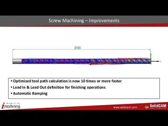
- 40. Screw Machining – Improvements Optimized tool path calculation is now 10 times or more faster Lead
- 41. SolidCAM Simulator What’s New in SolidCAM 2020
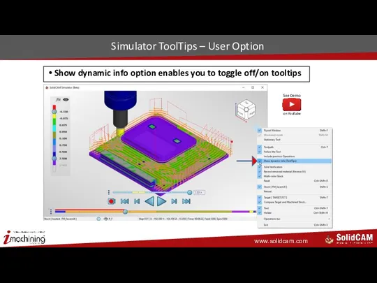
- 42. Simulator ToolTips – User Option Show dynamic info option enables you to toggle off/on tooltips
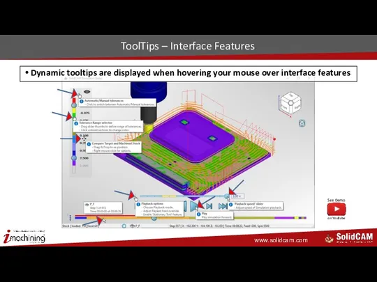
- 43. ToolTips – Interface Features Dynamic tooltips are displayed when hovering your mouse over interface features
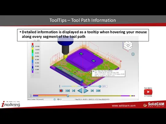
- 44. ToolTips – Tool Path Information Detailed information is displayed as a tooltip when hovering your mouse
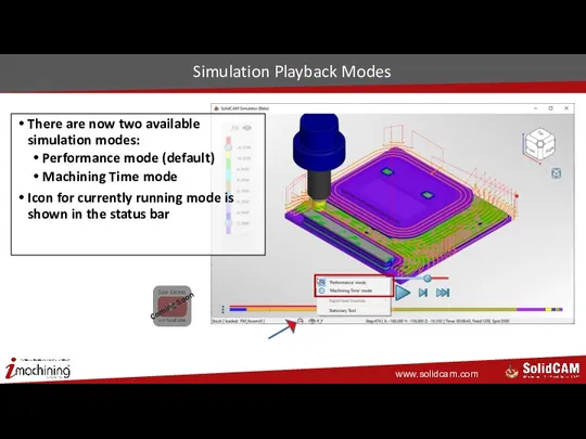
- 45. Simulation Playback Modes There are now two available simulation modes: Performance mode (default) Machining Time mode
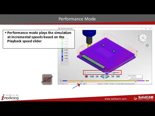
- 46. Performance Mode Performance mode plays the simulation at incremental speeds based on the Playback speed slider
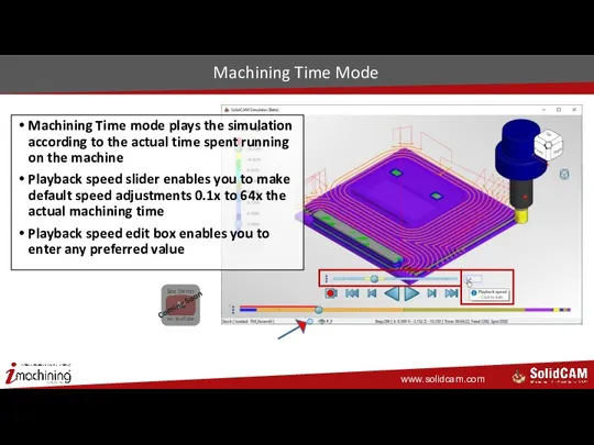
- 47. Machining Time Mode Machining Time mode plays the simulation according to the actual time spent running
- 48. Improved Status Bar with Tool Path Data Status bar now displays detailed information about the tool
- 49. Simulator Stationary Tool – User Option During simulation playback, you can now keep the tool stationary
- 50. Stationary Tool – Unique Views In top view, provides unique perspective on 3-Axis tool path that
- 51. General What’s New in SolidCAM 2020
- 52. Full Position Control of Part and Fixture Allows you in the Setup to set the absolute
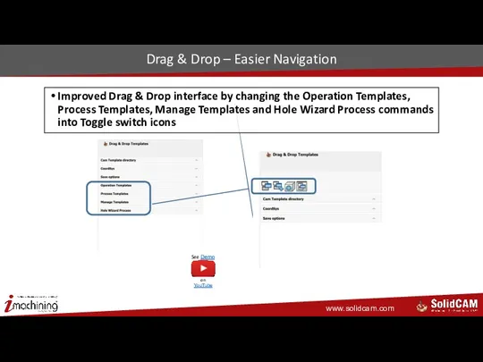
- 53. Drag & Drop – Easier Navigation Improved Drag & Drop interface by changing the Operation Templates,
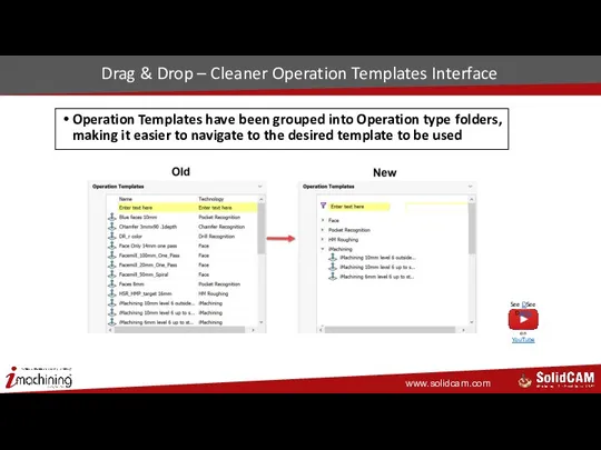
- 54. Drag & Drop – Cleaner Operation Templates Interface Operation Templates have been grouped into Operation type
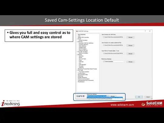
- 55. Saved Cam-Settings Location Default Gives you full and easy control as to where CAM settings are
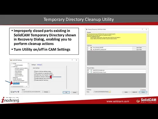
- 56. Temporary Directory Cleanup Utility Improperly closed parts existing in SolidCAM Temporary Directory shown in Recovery Dialog,
- 58. Скачать презентацию
2.5D Milling
What’s New in SolidCAM 2020
2.5D Milling
What’s New in SolidCAM 2020
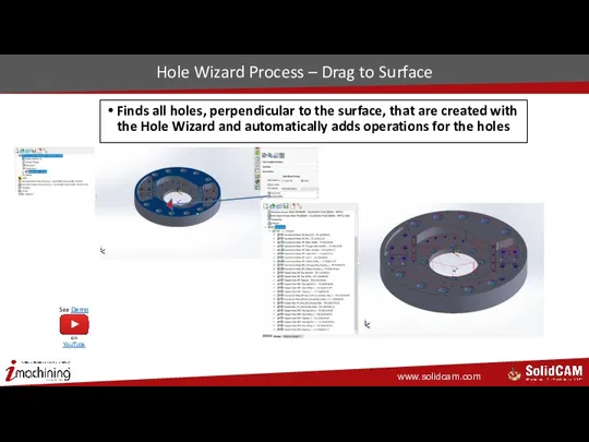
Hole Wizard Process – Drag to Surface
Finds all holes, perpendicular to
Hole Wizard Process – Drag to Surface
Finds all holes, perpendicular to
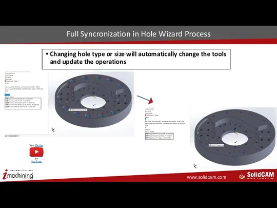
Full Syncronization in Hole Wizard Process
Changing hole type or size will
Full Syncronization in Hole Wizard Process
Changing hole type or size will
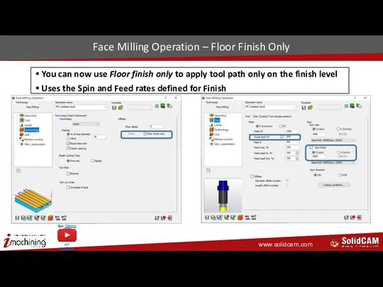
Face Milling Operation – Floor Finish Only
You can now use Floor
Face Milling Operation – Floor Finish Only
You can now use Floor
Pocket Operation – Floor Finish Only
You can now apply a Floor
Pocket Operation – Floor Finish Only
You can now apply a Floor
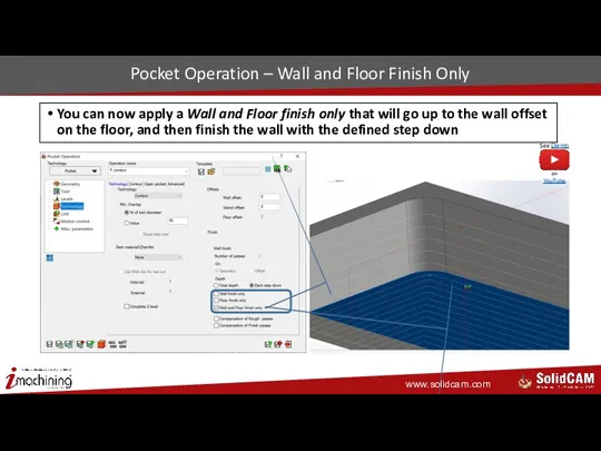
Pocket Operation – Wall and Floor Finish Only
You can now apply
Pocket Operation – Wall and Floor Finish Only
You can now apply
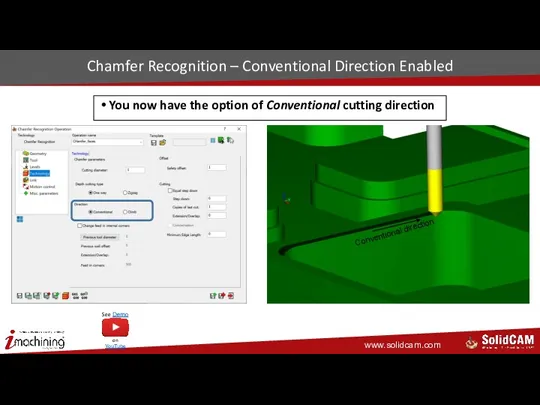
Chamfer Recognition – Conventional Direction Enabled
You now have the option of
Chamfer Recognition – Conventional Direction Enabled
You now have the option of
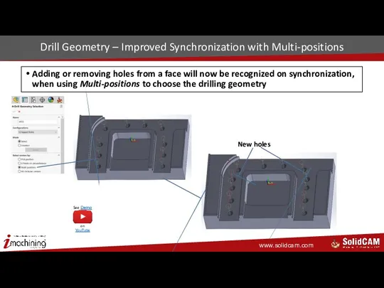
New holes
Drill Geometry – Improved Synchronization with Multi-positions
Adding or removing holes
New holes
Drill Geometry – Improved Synchronization with Multi-positions
Adding or removing holes
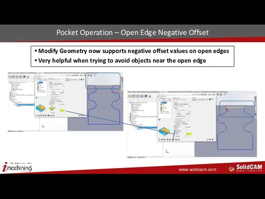
Pocket Operation – Open Edge Negative Offset
Modify Geometry now supports negative
Pocket Operation – Open Edge Negative Offset
Modify Geometry now supports negative
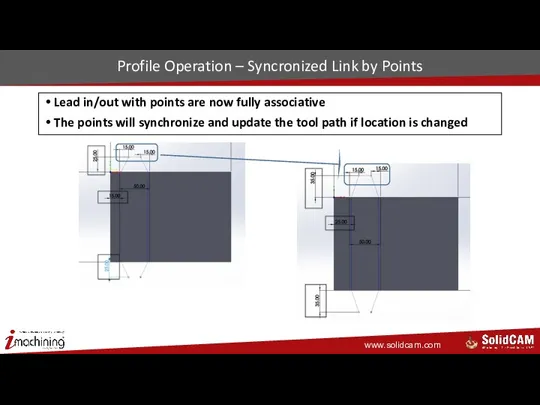
Profile Operation – Syncronized Link by Points
Lead in/out with points are
Profile Operation – Syncronized Link by Points
Lead in/out with points are

iMachining
What’s New in SolidCAM 2020
iMachining
What’s New in SolidCAM 2020
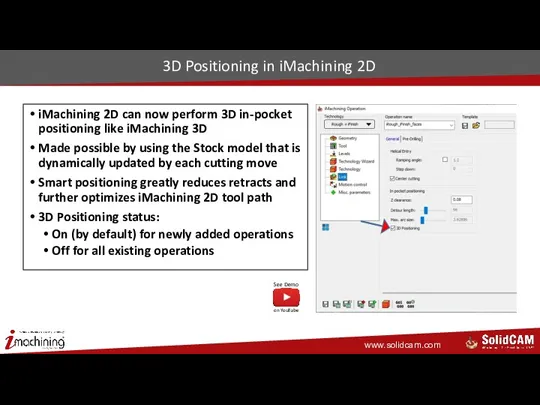
3D Positioning in iMachining 2D
iMachining 2D can now perform 3D
3D Positioning in iMachining 2D
iMachining 2D can now perform 3D
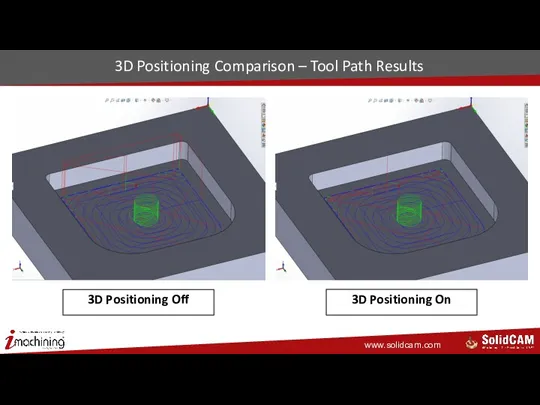
3D Positioning Comparison – Tool Path Results
3D Positioning Off
3D Positioning On
3D Positioning Comparison – Tool Path Results
3D Positioning Off
3D Positioning On
Machine Database from VMID and Station Data
iMachining Database now offers new
Machine Database from VMID and Station Data
iMachining Database now offers new
User-defined Arc Fitting Tolerance
iMachining tool path minimizes arcs according to a
User-defined Arc Fitting Tolerance
iMachining tool path minimizes arcs according to a
Arc Fitting Tolerance Comparison – GCode Results
Small arc fitting tolerance
Large arc
Arc Fitting Tolerance Comparison – GCode Results
Small arc fitting tolerance
Large arc
User-defined Max Cutting Angle Step-up in iMachining 3D
With each higher Step-up,
User-defined Max Cutting Angle Step-up in iMachining 3D
With each higher Step-up,
HSR/HSM
What’s New in SolidCAM 2020
HSR/HSM
What’s New in SolidCAM 2020
New Operation – Turbo 3D HSR
New Roughing Tool Path Engine
True 64-bit,
New Operation – Turbo 3D HSR
New Roughing Tool Path Engine
True 64-bit,
Turbo 3D HSR – Multicore Support
64-bit calculation engine – multicore support
Speed
Turbo 3D HSR – Multicore Support
64-bit calculation engine – multicore support
Speed
Turbo 3D HSR – Multiple Surface Offset
Turbo roughing allows multiple surface
Turbo 3D HSR – Multiple Surface Offset
Turbo roughing allows multiple surface
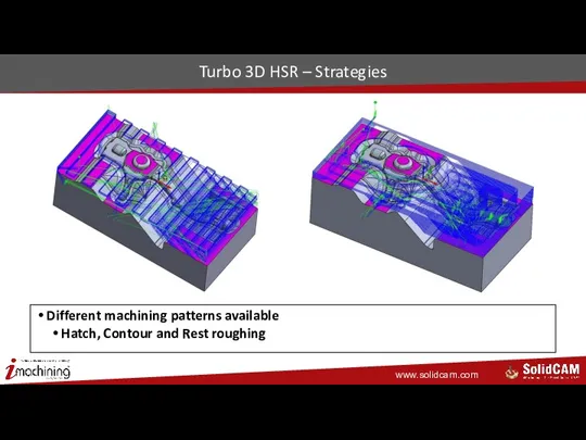
Turbo 3D HSR – Strategies
Different machining patterns available
Hatch, Contour and Rest
Turbo 3D HSR – Strategies
Different machining patterns available
Hatch, Contour and Rest
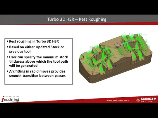
Turbo 3D HSR – Rest Roughing
Rest roughing in Turbo 3D HSR
Based
Turbo 3D HSR – Rest Roughing
Rest roughing in Turbo 3D HSR
Based
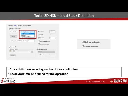
Turbo 3D HSR – Local Stock Definition
Stock definition including undercut stock
Turbo 3D HSR – Local Stock Definition
Stock definition including undercut stock
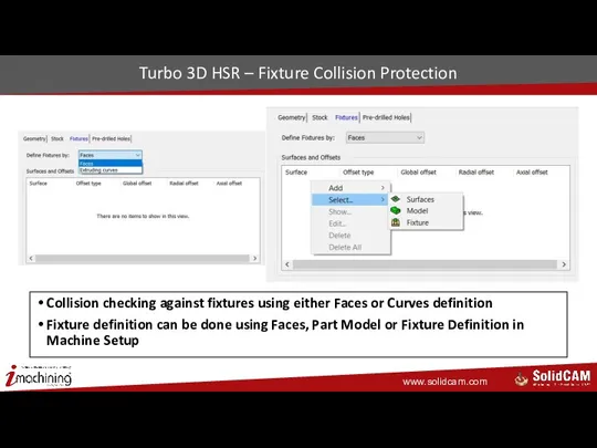
Turbo 3D HSR – Fixture Collision Protection
Collision checking against fixtures using
Turbo 3D HSR – Fixture Collision Protection
Collision checking against fixtures using
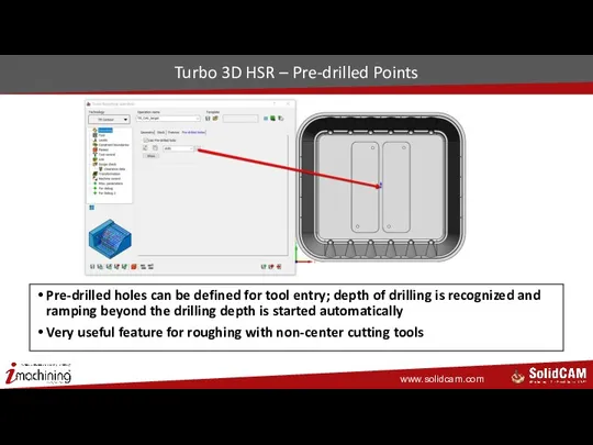
Turbo 3D HSR – Pre-drilled Points
Pre-drilled holes can be defined for
Turbo 3D HSR – Pre-drilled Points
Pre-drilled holes can be defined for
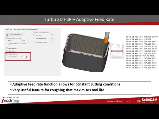
Turbo 3D HSR – Adaptive Feed Rate
Adaptive feed rate function allows
Turbo 3D HSR – Adaptive Feed Rate
Adaptive feed rate function allows
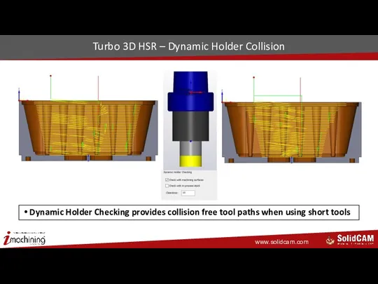
Turbo 3D HSR – Dynamic Holder Collision
Dynamic Holder Checking provides collision
Turbo 3D HSR – Dynamic Holder Collision
Dynamic Holder Checking provides collision
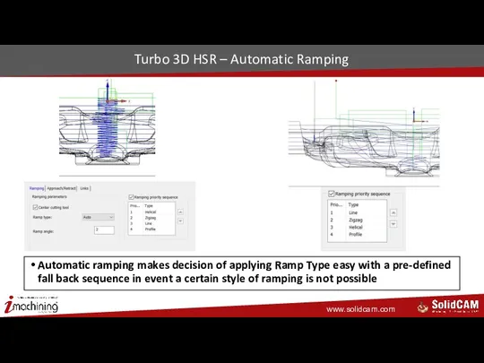
Turbo 3D HSR – Automatic Ramping
Automatic ramping makes decision of applying
Turbo 3D HSR – Automatic Ramping
Automatic ramping makes decision of applying
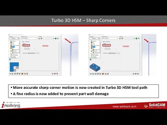
Turbo 3D HSM – Sharp Corners
More accurate sharp corner motion is
Turbo 3D HSM – Sharp Corners
More accurate sharp corner motion is
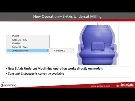
New Operation – 3-Axis Undercut Milling
New 3 Axis Undercut Machining operation
New Operation – 3-Axis Undercut Milling
New 3 Axis Undercut Machining operation
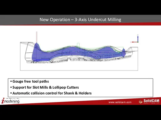
New Operation – 3-Axis Undercut Milling
Gouge free tool paths
Support for Slot
New Operation – 3-Axis Undercut Milling
Gouge free tool paths
Support for Slot

HSS & SIM 5X
What’s New in SolidCAM 2020
HSS & SIM 5X
What’s New in SolidCAM 2020
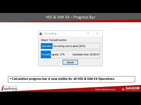
HSS & SIM 5X – Progress Bar
Calculation progress bar is now
HSS & SIM 5X – Progress Bar
Calculation progress bar is now
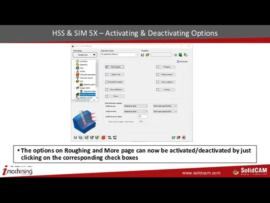
HSS & SIM 5X – Activating & Deactivating Options
The options on
HSS & SIM 5X – Activating & Deactivating Options
The options on
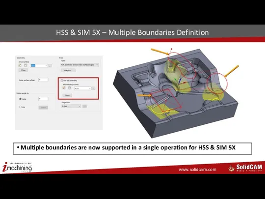
HSS & SIM 5X – Multiple Boundaries Definition
Multiple boundaries are now
HSS & SIM 5X – Multiple Boundaries Definition
Multiple boundaries are now
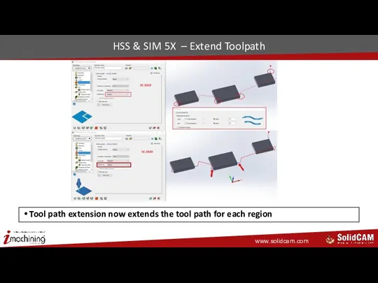
HSS & SIM 5X – Extend Toolpath
Tool path extension now extends
HSS & SIM 5X – Extend Toolpath
Tool path extension now extends
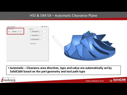
HSS & SIM 5X – Automatic Clearance Plane
Automatic – Clearance area
HSS & SIM 5X – Automatic Clearance Plane
Automatic – Clearance area
Screw Machining – Improvements
Optimized tool path calculation is now 10 times
Screw Machining – Improvements
Optimized tool path calculation is now 10 times
SolidCAM Simulator
What’s New in SolidCAM 2020
SolidCAM Simulator
What’s New in SolidCAM 2020
Simulator ToolTips – User Option
Show dynamic info option enables you to
Simulator ToolTips – User Option
Show dynamic info option enables you to
ToolTips – Interface Features
Dynamic tooltips are displayed when hovering your mouse
ToolTips – Interface Features
Dynamic tooltips are displayed when hovering your mouse
ToolTips – Tool Path Information
Detailed information is displayed as a tooltip
ToolTips – Tool Path Information
Detailed information is displayed as a tooltip
Simulation Playback Modes
There are now two available simulation modes:
Performance mode (default)
Machining
Simulation Playback Modes
There are now two available simulation modes:
Performance mode (default)
Machining
Performance Mode
Performance mode plays the simulation at incremental speeds based on
Performance Mode
Performance mode plays the simulation at incremental speeds based on
Machining Time Mode
Machining Time mode plays the simulation according to the
Machining Time Mode
Machining Time mode plays the simulation according to the
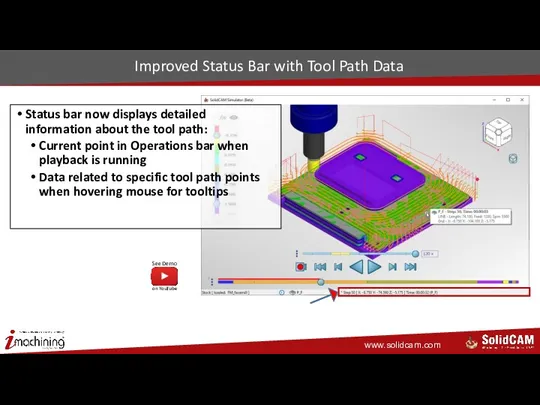
Improved Status Bar with Tool Path Data
Status bar now displays
Improved Status Bar with Tool Path Data
Status bar now displays
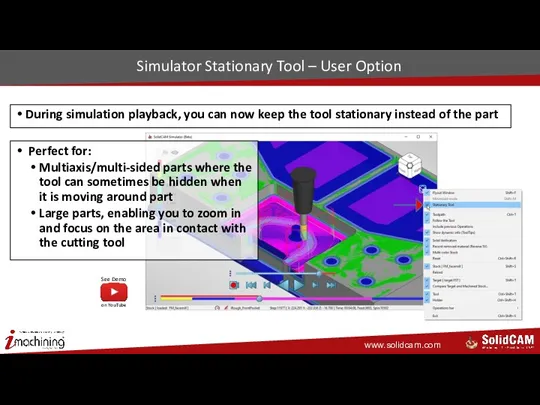
Simulator Stationary Tool – User Option
During simulation playback, you can now
Simulator Stationary Tool – User Option
During simulation playback, you can now
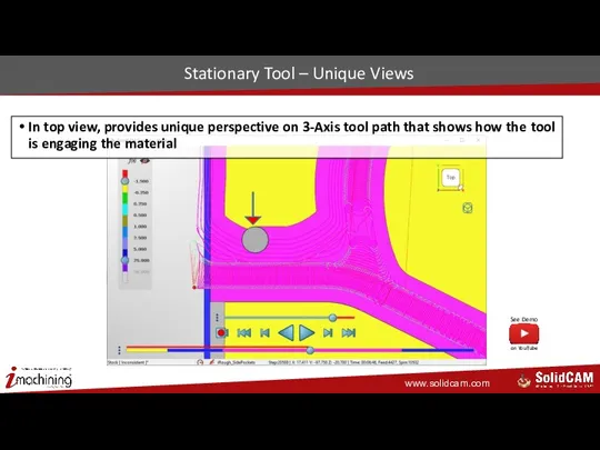
Stationary Tool – Unique Views
In top view, provides unique perspective on
Stationary Tool – Unique Views
In top view, provides unique perspective on

General
What’s New in SolidCAM 2020
General
What’s New in SolidCAM 2020
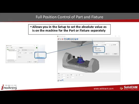
Full Position Control of Part and Fixture
Allows you in the
Full Position Control of Part and Fixture
Allows you in the
Drag & Drop – Easier Navigation
Improved Drag & Drop interface by
Drag & Drop – Easier Navigation
Improved Drag & Drop interface by
Drag & Drop – Cleaner Operation Templates Interface
Operation Templates have been
Drag & Drop – Cleaner Operation Templates Interface
Operation Templates have been
Saved Cam-Settings Location Default
Gives you full and easy control as to
Saved Cam-Settings Location Default
Gives you full and easy control as to
Temporary Directory Cleanup Utility
Improperly closed parts existing in SolidCAM Temporary Directory
Temporary Directory Cleanup Utility
Improperly closed parts existing in SolidCAM Temporary Directory
 Генетический алгоритм
 Дорожная карта телекоммуникационных продуктов на базе малых сот. Ситроникс
 Застосування умовних конструкцій в програмних додатках
 Компьютерные игры как жизнь
 Технология ввода текста. Редактирование текста
 Мова програмування swift
 Методология и технология разработки информационных систем
 Переход на обучение при помощи цифровых технологий (гаджетов)
 Разработка аппаратно-программного комплекса имитации нестабильности напряжения в сетях постоянного тока
 Информатика. Что означает термин “информатика” ? Что такое информация?
 Академическое письмо. Подготовка теоретической основы научного исследования
 Работа с Android. (Урок 4)
 О пределах и правилах заимствования информации при написании курсовых и дипломных работ
 Использование компьютера в различных отраслях
 Введение в СУБД ORACLE. Администрирование баз данных. Лекция 1
 Робота зі ЗМІ
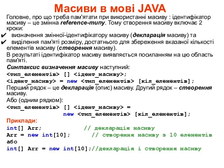 Масиви в мові Java
 Конспект открытого урока (с применением ЭОР)
 Графики и диаграммы
 Training material. Software licensing basics
 Проектирование автоматизированной системы управления технологическим процессом осушки газа
 Системы счисления
 Прогностические системы США
 TLS and SSL
 Презентация Ребусы
 Informatika va axborot texnologiyalari darslarida o‘quvchilarning bilim va ko‘nikmalarini shakllantirish uslubiyoti
 Комплексное решение для индустрии красоты на платформе 1С
 Компьютерные локальные сети и телекоммуникации связи