- The CCK 11 MBps Modulation for IEEE 802.11 2.4 GHz WLANs

Содержание
- 2. Summary CCK modulation will enable 11 MBps operation in the 2.4 GHz ISM band An interoperable
- 3. Preamble Length Our basic approach is to include the standard DS or FH 802.11 preamble and
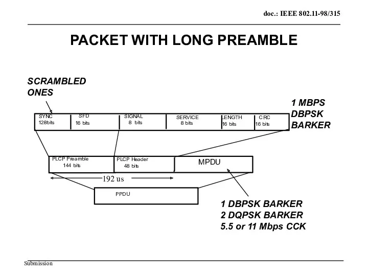
- 4. PLCP Preamble MPDU 144 bits SYNC SFD 16 bits SIGNAL 8 bits 8 bits 16 bits
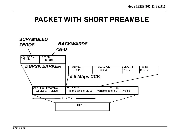
- 5. shortPLCP Preamble MPDU 72 bits @ 1 Mbit/s shortSYNC shortSFD 16 bits SIGNAL 8 bits 8
- 6. No Hit Ant A No Hit Ant B Hit Ant A Hit Ant B Hit Ant
- 7. No Hit Ant A No Hit Ant B Hit Ant A No Hit Ant B Hit
- 8. SHORT PREAMBLE PERFORMANCE SIMULATION PARAMETERS FREQ OFFSET: 50 PPM STATE: Linear (AGC locked) TIME SPAN: 10
- 10. FH Interoperability Preamble MPDU PPDU Short PLCP 120 BITS GAP FH PLCP Preamble 96 bits FH
- 11. Signal Field The 8 bit 802.11 Signal Field indicates to the PHY the modulation which shall
- 12. Length Field Since there is an ambiguity in the number of octets that will be described
- 13. FH PSF Field The first bit (#0) of the PSF which is reserved in clause 14.3.2.2.2
- 14. 11 MBps CCK 5.5 MBps CCK 802.11 DSSS QPSK 2MBps Barker QPSK 802.11 DSSS BPSK 1
- 15. CODE DIMENSIONALITY 8 QPSK CHIPS: 4^8 = 65536 CCK Code words 64 CCK Code words are
- 16. DIFFERENTIAL-PHASE MODULATION Code word Select Bits Differential- Phase Bits CODE WORD TABLE Code word rotate Code
- 17. Data Encoding 5.5 MBps Input data is broken into 4 bit nibbles where the first two
- 18. Chip Encoding @ 5.5 MBps 01 10 00 11 +I +Q -I -Q 01 10 00
- 19. Differential Encoding Dibit pattern (d(0),d(1)) d(0) is first in time Even Symbols Phase Change (+j ω
- 20. CCK Modulator Technique for 5.5 MBps Pick One of 4 Complex Codes * MUX 1:4 d2,
- 21. CCK Cover Sequences The only cover sequence so far defined is one that rotates the 4th
- 22. CCK Cover Code Rotations The data and cover code are performed in the I/Q domain and
- 23. Data Demodulation, 5.5 MBps A/D converter Compl. Mult Decover rotation Fast Walsh Transform Biggest Picker Sign
- 24. CCK Data Mapping The first output data bit of the Biggest Picker and sign detector represents
- 25. Data Encoding 11 MBps Input data is broken into bytes where the first two bits are
- 26. Encoding 11 MBps Continued Dibit pattern (d(i),d(i+1)) d(i) is first in time Phase 00 0 +1
- 27. CCK Modulator Technique for 11 MBps Modulation Pick One of 64 Complex Codes MUX 1:8 d2…d7
- 28. Data Demodulation, 11 MBps A/D converter Compl. Mult Decover Fast Walsh Transform Biggest Picker Sign Detector
- 29. Adjacent channel interference ACI @ 25 MHz separation: 30 - 35dB makes a 3 frequency channel
- 30. Receiver Minimum Input Level Sensitivity The Frame Error Rate (FER) shall be less than 8x10⁻² at
- 31. CCA mechanism and Co-Channel signal detection time We measure the correlated signal energy in the preamble
- 32. CCA The DSSS PHY shall provide the capability to perform Clear Channel Assessment (CCA) according to
- 33. CCA Threshold The CCK codes are not as easily detected as Barker Codes, so detection may
- 34. Interoperability CCK can recognize both long and short preambles. If the CCK receiver detects a short
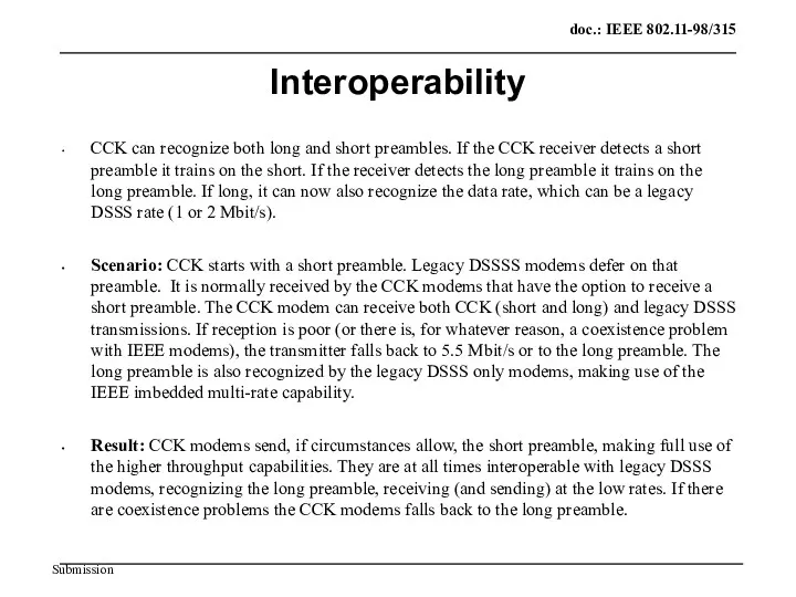
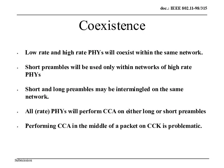
- 35. Coexistence Low rate and high rate PHYs will coexist within the same network. Short preambles will
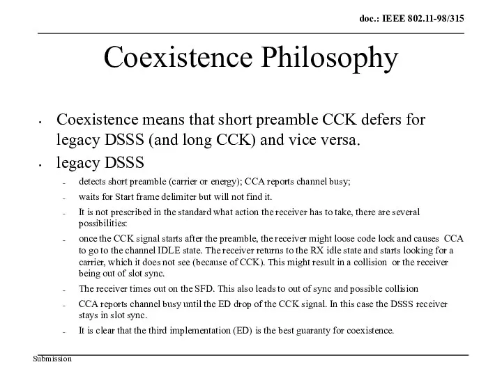
- 36. Coexistence Philosophy Coexistence means that short preamble CCK defers for legacy DSSS (and long CCK) and
- 38. Скачать презентацию
Summary
CCK modulation will enable 11 MBps operation in the 2.4 GHz
Summary
CCK modulation will enable 11 MBps operation in the 2.4 GHz
Preamble Length
Our basic approach is to include the standard DS or
Preamble Length
Our basic approach is to include the standard DS or
PLCP Preamble
MPDU
144 bits
SYNC
SFD
16 bits
SIGNAL
8 bits
8 bits
16 bits
LENGTH
CRC
128bits
SERVICE
PPDU
PLCP Header
48 bits
16
PLCP Preamble
MPDU
144 bits
SYNC
SFD
16 bits
SIGNAL
8 bits
8 bits
16 bits
LENGTH
CRC
128bits
SERVICE
PPDU
PLCP Header
48 bits
16
shortPLCP Preamble
MPDU
72 bits @ 1 Mbit/s
shortSYNC
shortSFD
16 bits
SIGNAL
8 bits
8 bits
16 bits
LENGTH
CRC
56
shortPLCP Preamble
MPDU
72 bits @ 1 Mbit/s
shortSYNC
shortSFD
16 bits
SIGNAL
8 bits
8 bits
16 bits
LENGTH
CRC
56
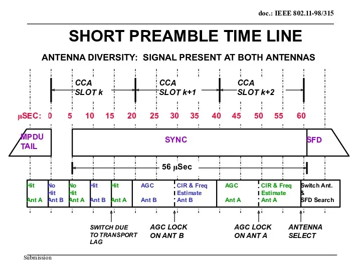
No
Hit
Ant A
No
Hit
Ant B
Hit
Ant A
Hit
Ant B
Hit
Ant A
AGC
Ant B
AGC
Ant A
CIR
No
Hit
Ant A
No
Hit
Ant B
Hit
Ant A
Hit
Ant B
Hit
Ant A
AGC
Ant B
AGC
Ant A
CIR
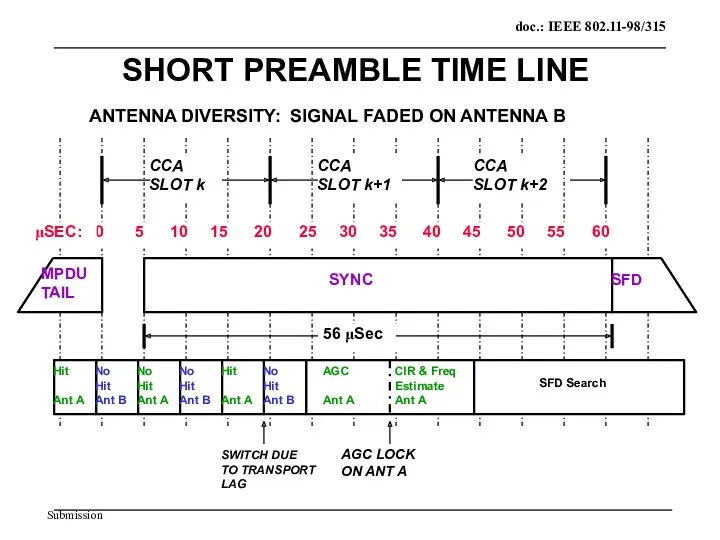
No
Hit
Ant A
No
Hit
Ant B
Hit
Ant A
No
Hit
Ant B
Hit
Ant A
AGC
Ant A
CIR &
No
Hit
Ant A
No
Hit
Ant B
Hit
Ant A
No
Hit
Ant B
Hit
Ant A
AGC
Ant A
CIR &
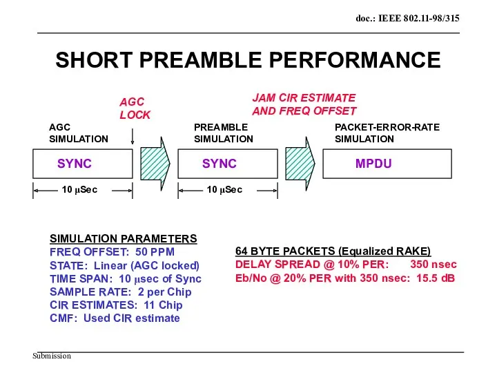
SHORT PREAMBLE PERFORMANCE
SIMULATION PARAMETERS
FREQ OFFSET: 50 PPM
STATE: Linear (AGC locked)
TIME SPAN:
SHORT PREAMBLE PERFORMANCE
SIMULATION PARAMETERS
FREQ OFFSET: 50 PPM
STATE: Linear (AGC locked)
TIME SPAN:
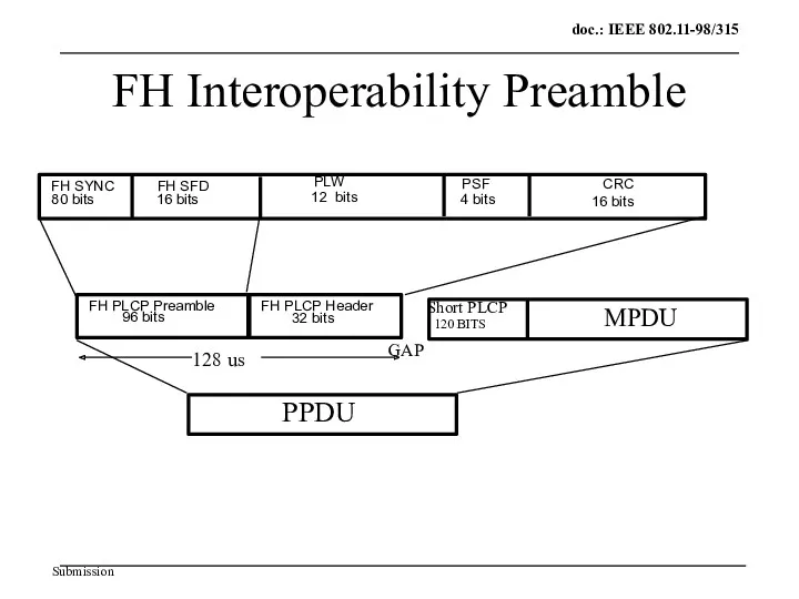
FH Interoperability Preamble
MPDU
PPDU
Short PLCP
120 BITS
GAP
FH PLCP Preamble
96 bits
FH SYNC
FH SFD
16
FH Interoperability Preamble
MPDU
PPDU
Short PLCP
120 BITS
GAP
FH PLCP Preamble
96 bits
FH SYNC
FH SFD
16
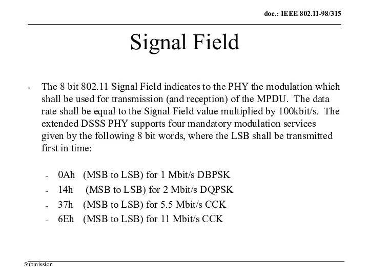
Signal Field
The 8 bit 802.11 Signal Field indicates to the PHY
Signal Field
The 8 bit 802.11 Signal Field indicates to the PHY
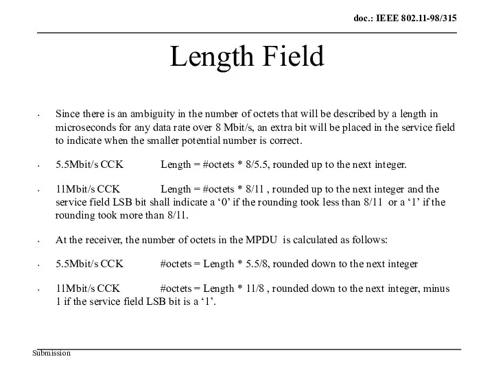
Length Field
Since there is an ambiguity in the number of octets
Length Field
Since there is an ambiguity in the number of octets
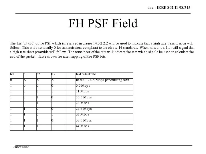
FH PSF Field
The first bit (#0) of the PSF which is
FH PSF Field
The first bit (#0) of the PSF which is
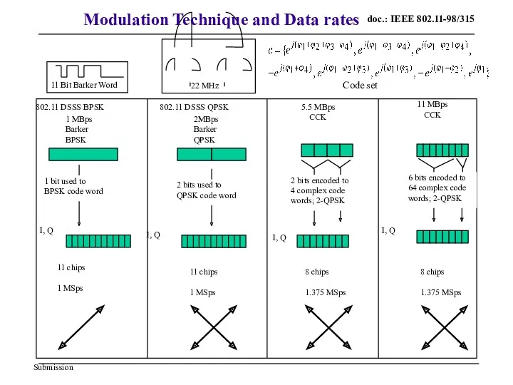
11 MBps
CCK
5.5 MBps
CCK
802.11 DSSS QPSK
2MBps
Barker
QPSK
802.11 DSSS BPSK
1 MBps
Barker
BPSK
11 chips
1 MSps
1 bit
11 MBps
CCK
5.5 MBps
CCK
802.11 DSSS QPSK
2MBps
Barker
QPSK
802.11 DSSS BPSK
1 MBps
Barker
BPSK
11 chips
1 MSps
1 bit
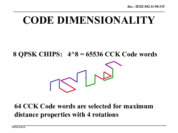
CODE DIMENSIONALITY
8 QPSK CHIPS: 4^8 = 65536 CCK Code words
64 CCK
CODE DIMENSIONALITY
8 QPSK CHIPS: 4^8 = 65536 CCK Code words
64 CCK
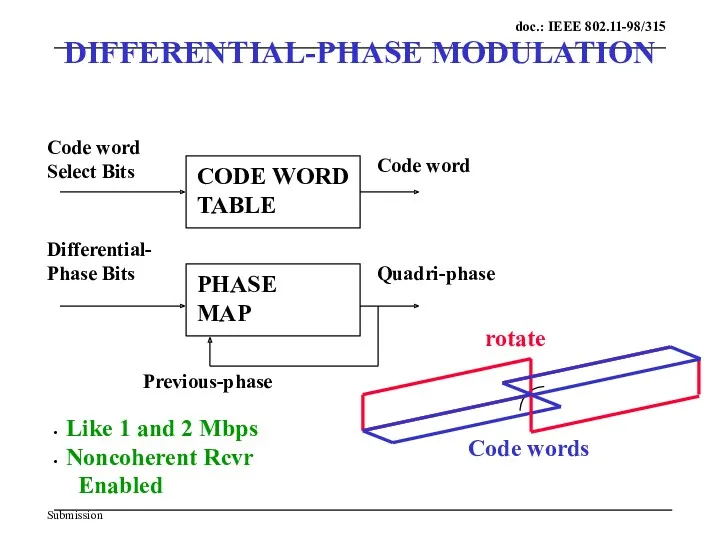
DIFFERENTIAL-PHASE MODULATION
Code word
Select Bits
Differential-
Phase Bits
CODE WORD
TABLE
Code word
rotate
Code words
PHASE
MAP
Quadri-phase
Previous-phase
Like 1 and
DIFFERENTIAL-PHASE MODULATION
Code word
Select Bits
Differential-
Phase Bits
CODE WORD
TABLE
Code word
rotate
Code words
PHASE
MAP
Quadri-phase
Previous-phase
Like 1 and
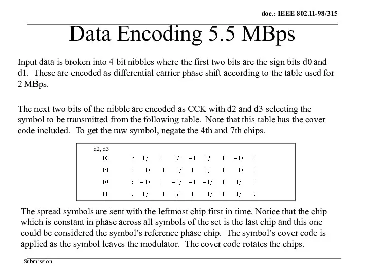
Data Encoding 5.5 MBps
Input data is broken into 4 bit nibbles
Data Encoding 5.5 MBps
Input data is broken into 4 bit nibbles
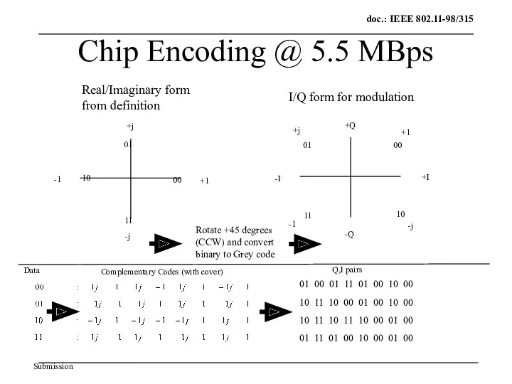
Chip Encoding @ 5.5 MBps
01
10
00
11
+I
+Q
-I
-Q
01
10
00
11
+1
+j
-1
-j
Rotate +45 degrees
(CCW) and convert
binary to
Chip Encoding @ 5.5 MBps
01
10
00
11
+I
+Q
-I
-Q
01
10
00
11
+1
+j
-1
-j
Rotate +45 degrees
(CCW) and convert
binary to
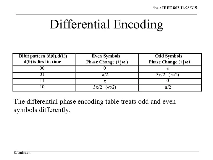
Differential Encoding
Dibit pattern (d(0),d(1))
d(0) is first in time
Even Symbols
Phase Change (+j
ω
)
Odd
Differential Encoding
Dibit pattern (d(0),d(1))
d(0) is first in time
Even Symbols
Phase Change (+j
ω
)
Odd
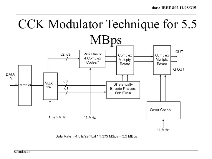
CCK Modulator Technique for 5.5 MBps
Pick One of
4 Complex
Codes *
MUX
1:4
d2,
CCK Modulator Technique for 5.5 MBps
Pick One of
4 Complex
Codes *
MUX
1:4
d2,
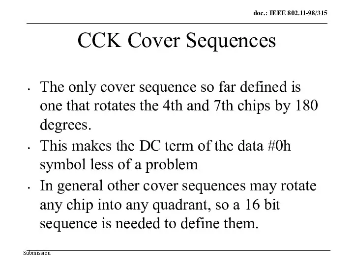
CCK Cover Sequences
The only cover sequence so far defined is one
CCK Cover Sequences
The only cover sequence so far defined is one
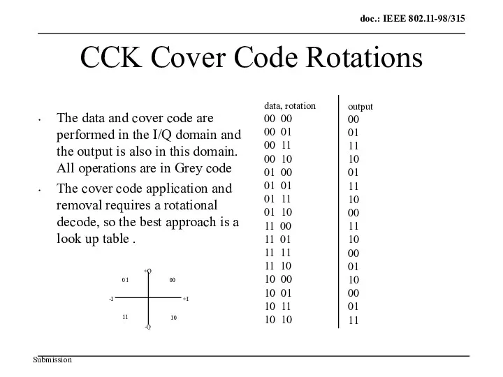
CCK Cover Code Rotations
The data and cover code are performed in
CCK Cover Code Rotations
The data and cover code are performed in
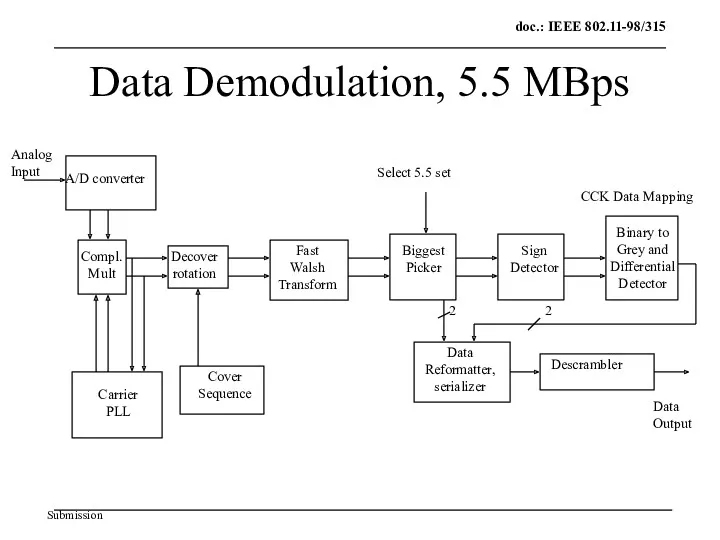
Data Demodulation, 5.5 MBps
A/D converter
Compl.
Mult
Decover
rotation
Fast
Walsh
Transform
Biggest
Picker
Sign
Detector
Carrier
PLL
Binary to
Grey and
Differential
Detector
Select 5.5 set
Cover
Sequence
Analog
Input
Data
Data Demodulation, 5.5 MBps
A/D converter
Compl.
Mult
Decover
rotation
Fast
Walsh
Transform
Biggest
Picker
Sign
Detector
Carrier
PLL
Binary to
Grey and
Differential
Detector
Select 5.5 set
Cover
Sequence
Analog
Input
Data
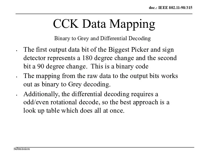
CCK Data Mapping
The first output data bit of the Biggest Picker
CCK Data Mapping
The first output data bit of the Biggest Picker
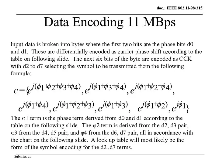
Data Encoding 11 MBps
Input data is broken into bytes where the
Data Encoding 11 MBps
Input data is broken into bytes where the
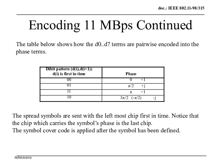
Encoding 11 MBps Continued
Dibit pattern (d(i),d(i+1))
d(i) is first in time
Phase
00
0 +1
01
π
/2 +j
11
π −1
10
3
π
/2 (-
π
/2)
Encoding 11 MBps Continued
Dibit pattern (d(i),d(i+1))
d(i) is first in time
Phase
00
0 +1
01
π
/2 +j
11
π −1
10
3
π
/2 (-
π
/2)
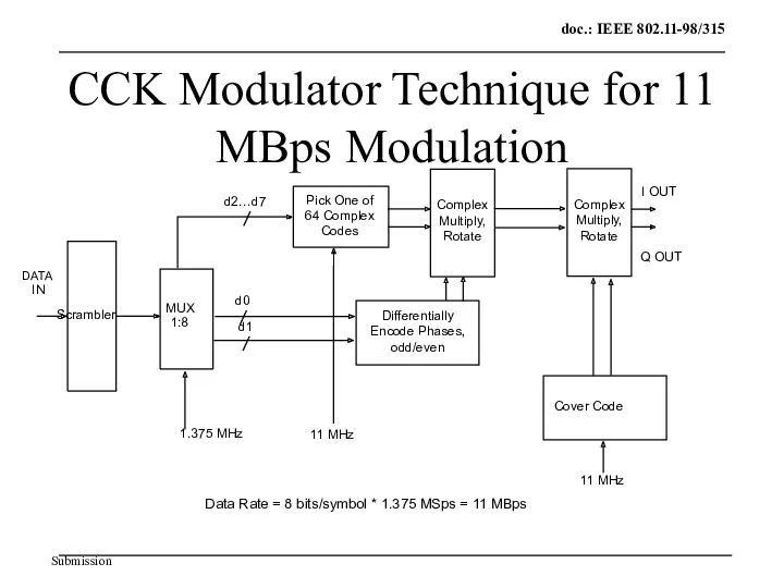
CCK Modulator Technique for 11 MBps Modulation
Pick One of
64 Complex
Codes
CCK Modulator Technique for 11 MBps Modulation
Pick One of
64 Complex
Codes
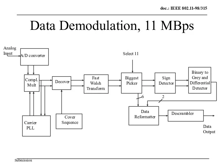
Data Demodulation, 11 MBps
A/D converter
Compl.
Mult
Decover
Fast
Walsh
Transform
Biggest
Picker
Sign
Detector
Carrier
PLL
Binary to
Grey and
Differential
Detector
Select 11
Cover
Sequence
Analog
Input
Data
Output
Descrambler
Data
Data Demodulation, 11 MBps
A/D converter
Compl.
Mult
Decover
Fast
Walsh
Transform
Biggest
Picker
Sign
Detector
Carrier
PLL
Binary to
Grey and
Differential
Detector
Select 11
Cover
Sequence
Analog
Input
Data
Output
Descrambler
Data
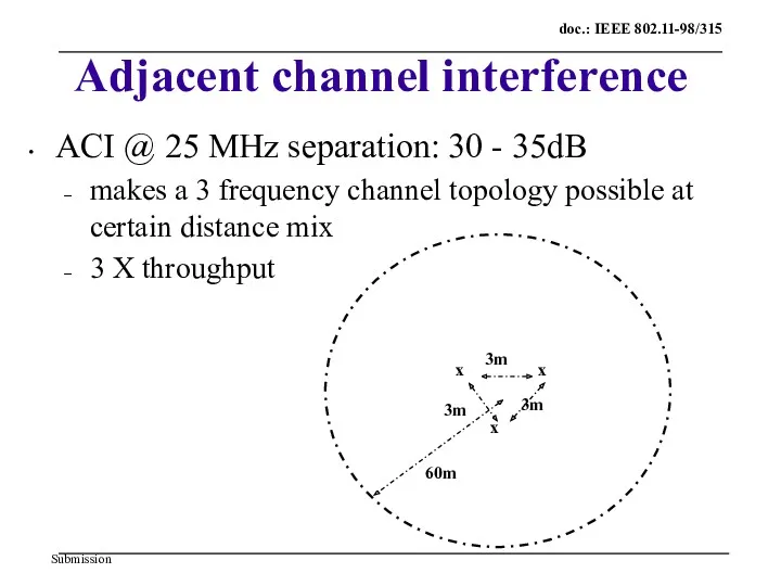
Adjacent channel interference
ACI @ 25 MHz separation: 30 - 35dB
makes a
Adjacent channel interference
ACI @ 25 MHz separation: 30 - 35dB
makes a
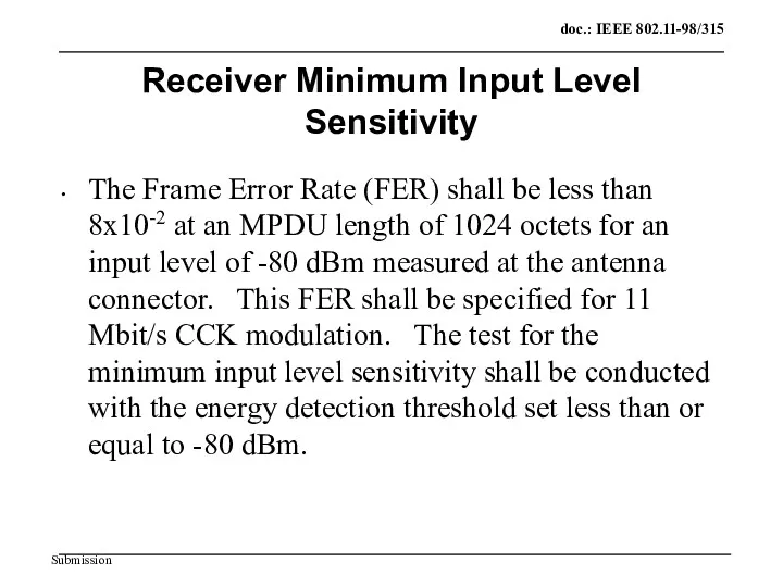
Receiver Minimum Input Level Sensitivity
The Frame Error Rate (FER) shall be
Receiver Minimum Input Level Sensitivity
The Frame Error Rate (FER) shall be
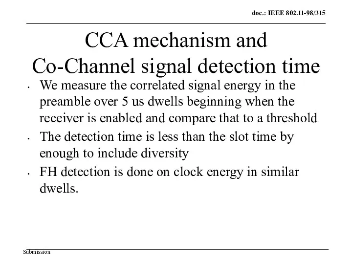
CCA mechanism and
Co-Channel signal detection time
We measure the correlated signal
CCA mechanism and
Co-Channel signal detection time
We measure the correlated signal
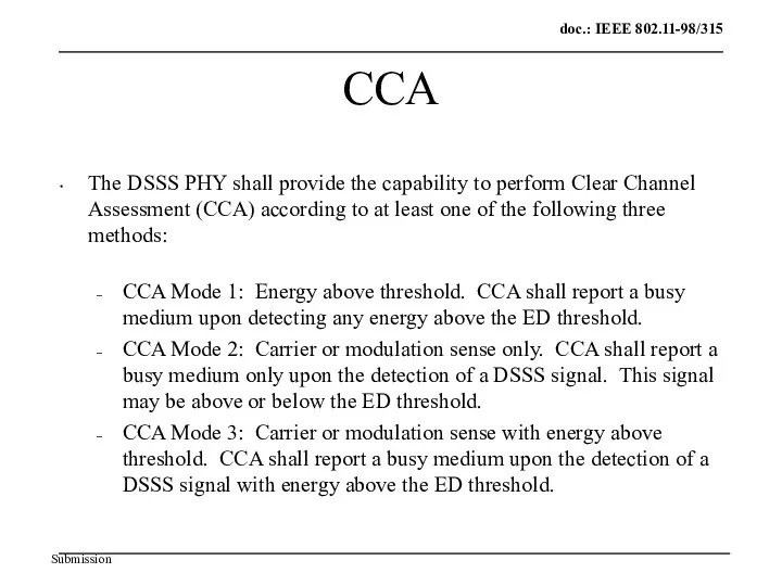
CCA
The DSSS PHY shall provide the capability to perform Clear Channel
CCA
The DSSS PHY shall provide the capability to perform Clear Channel
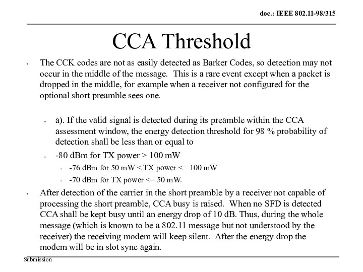
CCA Threshold
The CCK codes are not as easily detected as Barker
CCA Threshold
The CCK codes are not as easily detected as Barker
Interoperability
CCK can recognize both long and short preambles. If the CCK
Interoperability
CCK can recognize both long and short preambles. If the CCK
Coexistence
Low rate and high rate PHYs will coexist within the same
Coexistence
Low rate and high rate PHYs will coexist within the same
Coexistence Philosophy
Coexistence means that short preamble CCK defers for legacy DSSS
Coexistence Philosophy
Coexistence means that short preamble CCK defers for legacy DSSS
 International Economic Analysis 8
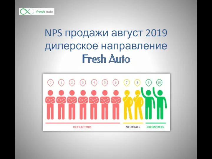 NPS продажи. Дилерское направление Fresh Auto (1)
 Планирование маркетинговой деятельности на примере British Airways
 Свадебная студия Wedding Angel. Арендный фонд
 Как зарабатывать деньги сегодня. Орифлэйм
 Кейс Десертайм
 ЗАО ДИГС Групп. Производство безалкогольных и слабоалкогольных напитков
 Бріф на акцію C4P 4+1
 Another SEO Tactics You Should Implement Tonight
 Конкуренты производителей медицинских услуг
 Концепция новогоднего мероприятия для детей сотрудников компании
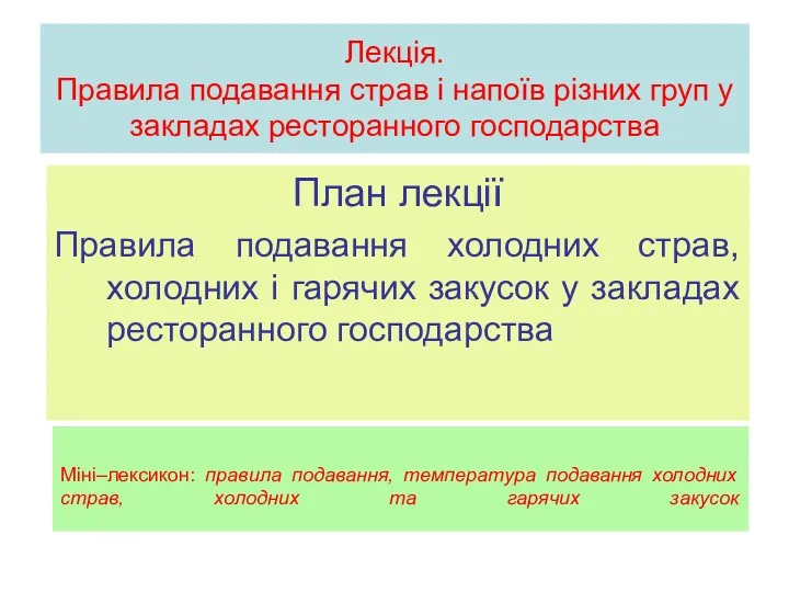 Лекція. Правила подавання страв і напоїв різних груп у закладах ресторанного господарства
 Рекламное агентство Седьмой гость
 Что такое SMA? Как успешно зарабатывать на финансовых рынках
 LeadMedia. Поток клиентов для вашего бизнеса
 Реклама Audi
 Федеральный интернет - магазин Автополка
 Анализ конкурентоспособности фирмы
 Генератор продаж. Поставки клиентов из сети. SEO продвижение
 Kinder. New Year Shows. Новогоднее шоу
 Анализ существующего фирменного стиля костромского технологического техникума и его применение в рекламной продукции
 Схема организации работы по телефону
 Италия. VIP-тур
 Основы маркетинга
 Дневник исследования нового сладкого продукта Nutella
 Приглашение на концерт Её величество - женщина!
 Идеи корпоративных подарков на Новый год
 AZIMUT Hotel Sochi – Ваш незабываемый отдых в Сочи