- Nanoknife. Overview. Physician training

Содержание
- 2. Agenda What is Nanoknife? The system Peri-Operative Considerations Nanoknife Treatment Planning Software Planning Procedure, Tips &
- 3. WHAT IS NANOKNIFE?
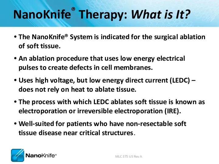
- 4. NanoKnife® Therapy: What is It? The NanoKnife® System is indicated for the surgical ablation of soft
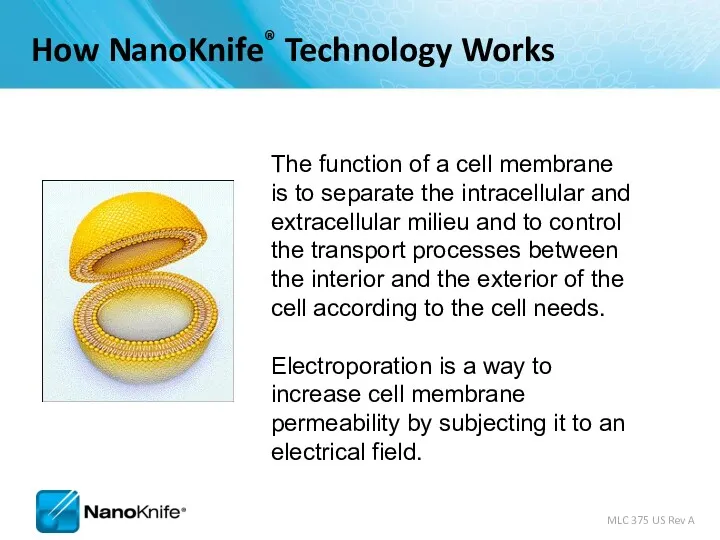
- 5. The function of a cell membrane is to separate the intracellular and extracellular milieu and to
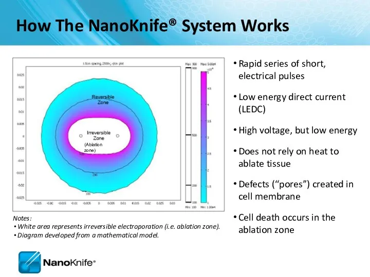
- 6. Rapid series of short, electrical pulses Low energy direct current (LEDC) High voltage, but low energy
- 7. Electroporation S. Dev, D. Rabussay, D. Widera, G. Hoffman, IEEE Trans. Plasma Sci, 2000 Note: Cell
- 8. Uses high voltage, low energy electrical pulses to achieve tissue effect Does not rely on heat
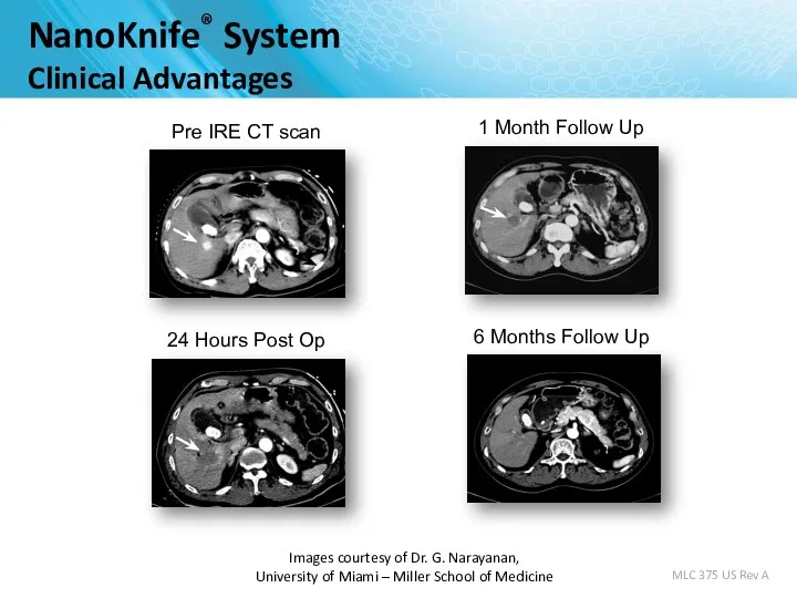
- 9. Images courtesy of Dr. G. Narayanan, University of Miami – Miller School of Medicine MLC 375
- 10. Image Source: B Rubinsky et al, Technology in Cancer Research and Treatment, 2007 NanoKnife lends itself
- 11. 1.6cm by 2.6cm 1.5cm Probe Spacing Two Electrodes, 15 mm space, 2500 volt Image Source: AngioDynamics
- 12. Immediately Post-Ablation Visualized Under Ultrasound Image Source: AngioDynamics pre-clinical research porcine liver post-ablation.
- 13. THE NANOKNIFE SYSTEM
- 14. FDA 510(k) clearance for the surgical ablation of soft tissue. It has not received clearance for
- 15. Monopolar Electrode Single Electrode Disposable 15 cm length 25 cm length In the event insufflation is
- 16. Monopolar Electrode Key Features 19 gauge needle with depth markings Echogenic needle surface Active electrode length
- 17. Activation Probe
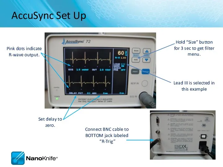
- 18. External synchronization device. The ECG Trigger Monitor automatically detects the R Wave (when energy is delivered)
- 19. Energy Delivery 0 15 30 45 60 75 90 105 120 135 0 3kV max Synchronized
- 20. Why NanoKnife® Therapy? Differentiate your institution from competing hospitals On the cutting edge of defining new
- 21. PERI-OPERATIVE CONSIDERATIONS University of Louisville
- 22. Objectives NanoKnife Components Room Set Up Patient Set Up Anesthesia Considerations Treatment Planning Procedural Overview
- 23. NanoKnife System consists of the NanoKnife® System
- 24. NANOKNIFE ROOM PREPARATION
- 25. Room Preparation General anesthesia cart All monitoring & resuscitation equipment required for general anesthesia per ASA
- 26. Patient Set up Position patient for optimal access Consider type of access; percutaneous, laparoscopic, open Consider
- 27. Patient Set Up (Cont’d) Physician to discuss with anesthesiologist Muscle blockade required during energy delivery Alert
- 28. ECG Sync Device – Patient Lead Set Up
- 29. Pink dots indicate R-wave output. Set delay to zero. Lead III is selected in this example
- 30. PROCEDURAL OVERVIEW
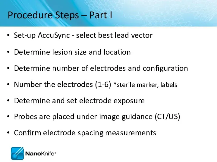
- 31. Procedure Steps – Part I Set-up AccuSync - select best lead vector Determine lesion size and
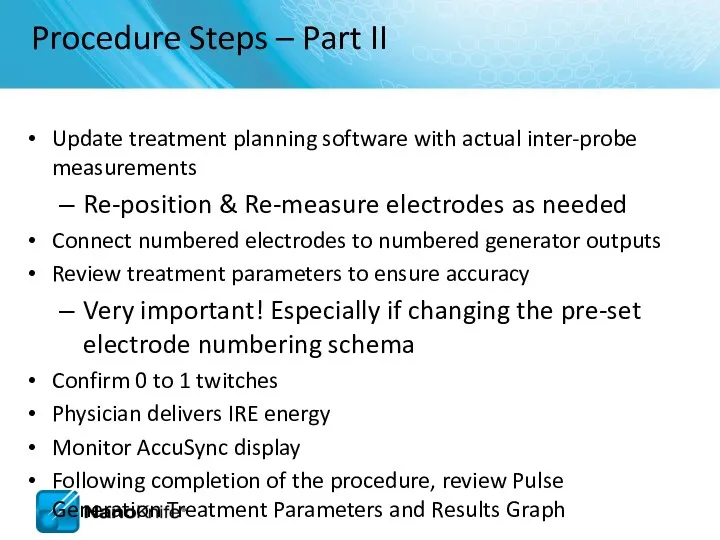
- 32. Procedure Steps – Part II Update treatment planning software with actual inter-probe measurements Re-position & Re-measure
- 33. SOFTWARE PLANNING
- 34. Getting Started Confirm the updated software is in place during start up
- 35. Information Screen There are five sections in the Information screen 1 2 3 4 5
- 36. Patient Information
- 37. Case Information Key information about the case (e.g. type of chemotherapy they completed etc. ) Auto
- 38. Clinical Data Enter lesion type Enter dimensions
- 39. Tool Bar
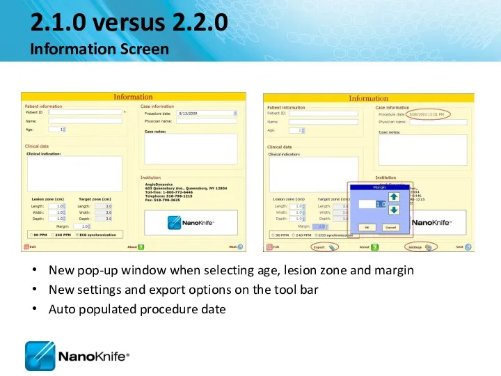
- 40. 2.1.0 versus 2.2.0 Information Screen New pop-up window when selecting age, lesion zone and margin New
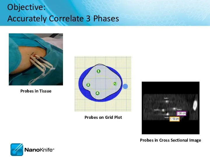
- 41. Objective: Accurately Correlate 3 Phases Probes in Tissue Probes on Grid Plot Probes in Cross Sectional
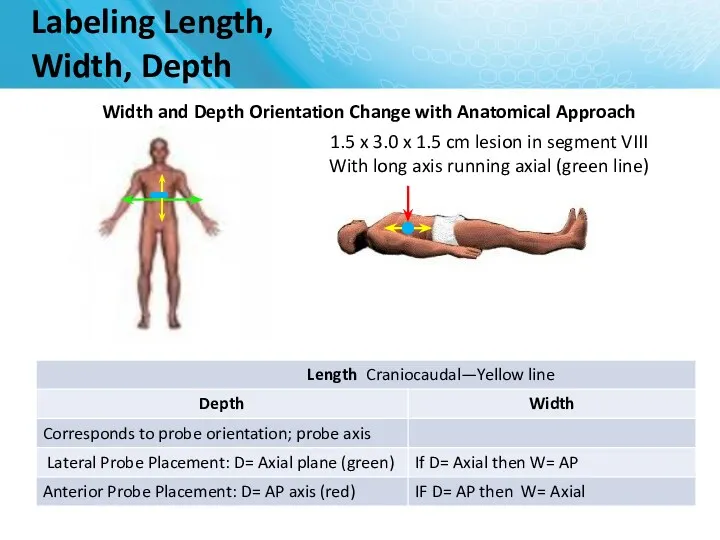
- 42. Labeling Length, Width, Depth Width and Depth Orientation Change with Anatomical Approach 1.5 x 3.0 x
- 43. NanoKnife Treatment Planning Estimate Number of Probes... Based on longest axis of lesion 3 probe array
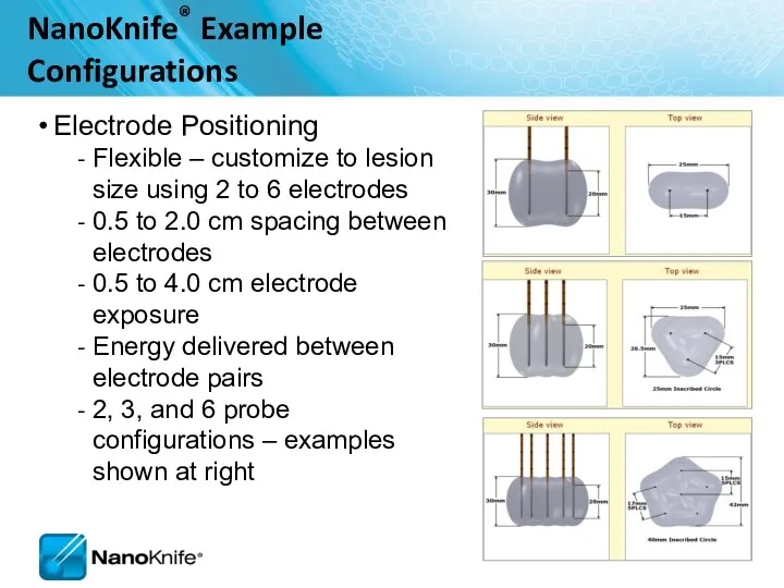
- 44. Electrode Positioning Flexible – customize to lesion size using 2 to 6 electrodes 0.5 to 2.0
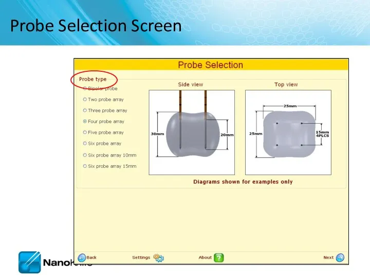
- 45. Probe Selection Screen
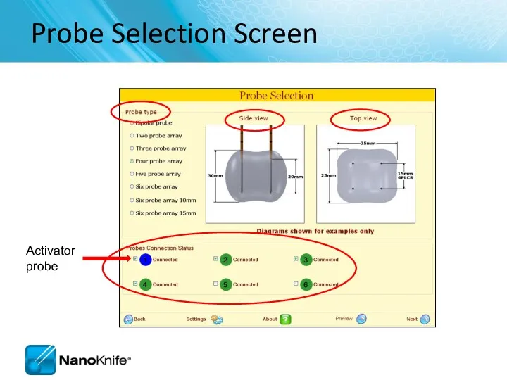
- 46. Probe Selection Screen
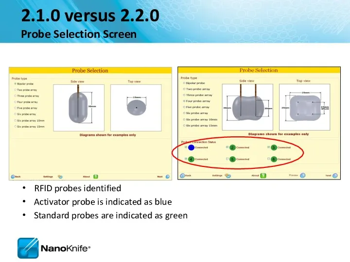
- 47. 2.1.0 versus 2.2.0 Probe Selection Screen RFID probes identified Activator probe is indicated as blue Standard
- 48. Probe Placement Grid Probe icons Probe Exposure notated here
- 49. Head Orient Grid to Anatomical Approach Anterior Probe Placement into 1.5 x 3.0 x 1.5 lesion
- 50. Orient Grid to Anatomical Approach Head Lateral Probe Placement 1.5 x 3.0 x 1.5 lesion Depth
- 51. Probe Placement Process Screen 1 2 3 4 5
- 52. Probe Placement Grid Probes Target tissue (yellow) Ablation area (gray) Fiducials Skipped Ablation
- 53. Probe Placement Grid Save initial set up Clear ablations
- 54. Ablation Spreadsheet Enter probe distances and have them automatically placed on the grid
- 55. Adjusting Voltage Change setting to obtain required Volts/cm
- 56. Probe Dock and Exposure Table Disconnect / reconnect the probes from the Generator
- 57. Hint Box Hints box provides additional instructions
- 58. 2.1.0 versus 2.2.0 Probe Placement Screen Probe Placement Grid is larger Skipped lesions identified Overlapping Ablation
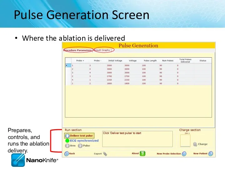
- 59. Pulse Generation Screen Where the ablation is delivered
- 60. If unsuccessful, the system will guide the user to check the probe connections to ensure they
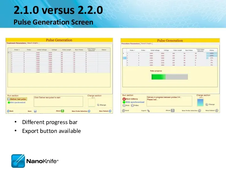
- 61. 2.1.0 versus 2.2.0 Pulse Generation Screen Different progress bar Export button available
- 62. Ablation Delivery Completed
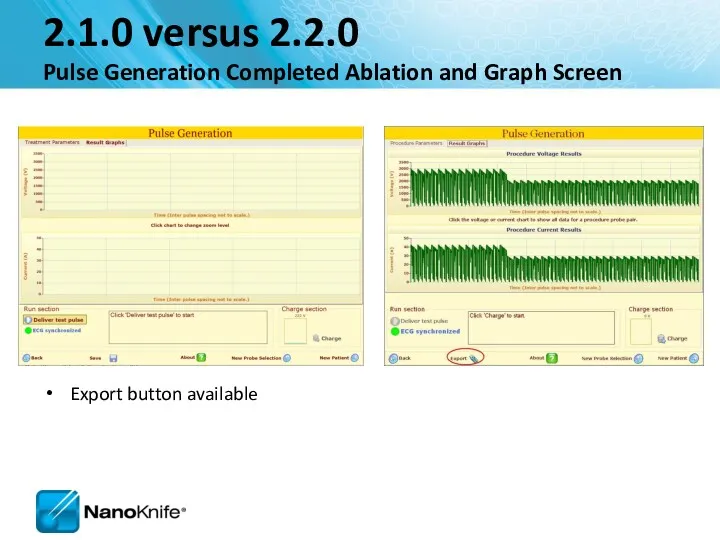
- 63. 2.1.0 versus 2.2.0 Pulse Generation Completed Ablation and Graph Screen Export button available
- 64. Pulse Generation screen Confirm level of neuromuscular blockade now
- 65. Run Section If unsuccessful, the system will guide the user to check the probe connections to
- 66. Four Probe Ablation Sequence 1 2 3 4
- 67. Pulse Generation Completed
- 68. View Results Graph
- 69. NANOKNIFE TREATMENT PLANNING – PRACTICAL CONSIDERATIONS USING 2.1.0 LESION ESTIMATOR For Training Purpose Only- Not For
- 70. Target organs Liver Pancreas Lung Kidney Manageable starting points Endophytic lesions ≤ 2cm Single probe groupings
- 71. NanoKnife Treatment Planning Estimate Number of Probes... Based on longest axis of lesion 3 probe array
- 72. Keep electrodes parallel Avoid convergence Tips are closer together Avoid divergence Tips are further apart Equal
- 73. Optimum Placement Parameters For Training Purpose Only- Not For Dissemination to Customers
- 74. Treatment Planning Parameters For Training Purpose Only- Not For Dissemination to Customers
- 75. How can you tell if you got an effective treatment? Short answer: There are no certain
- 76. Hydrolysis is the dissociation of water molecules A ‘muffled’ sound during pulses is common and benign
- 77. It’s always a good idea to… RE-IMAGE when probe placement, inter-probe distance or relative ablation zone
- 78. Liver Good starting place Possibility for combined treatment on larger lesions (IRE at/near critical structures +
- 79. Kidney Very conductive ( draws 20-23 Amps) 2-2.5 max probe exposure Pulses into adrenal gland can
- 80. Procedure Tips, Tricks, and Troubleshooting September 16, 2010
- 81. Learning Objectives NanoKnife Set-Up AccuSync 72 Set-Up ECG Synchronized Pulse Delivery Proper Sync Function ECG Sync
- 82. NanoKnife Set-Up The power button is located on the back panel of the generator. This is
- 83. Demo Mode In the event the system boots in demo mode, check to make sure the
- 84. Power Switch Patient Leads AccuSync Set-Up For Training Purpose Only- Not For Dissemination to Customers
- 85. AccuSync Set Up For Training Purpose Only- Not For Dissemination to Customers Recommend attaching AccuSync Leads
- 86. Software with AccuSync The generator will start in ECG Synchronization mode (default setting) You won’t be
- 87. Select 2-3 leads with the Biggest R wave and smallest T wave Tip: Use same lead
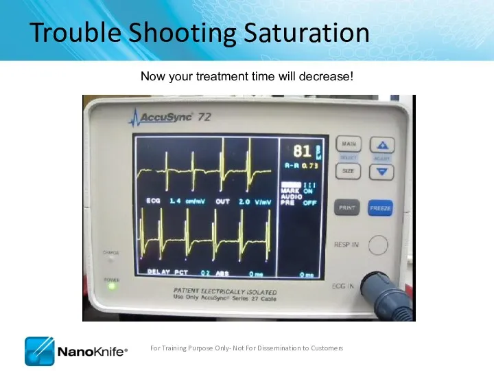
- 88. ECG Synchronized Pulse Delivery Sync device (e.g. AccuSync 72) senses the rising slope of the R-wave,
- 89. No Saturation For Training Purpose Only- Not For Dissemination to Customers
- 90. Heavy Saturation Recommend changing lead pair to resolve saturation For Training Purpose Only- Not For Dissemination
- 91. Trouble Shooting Saturation Remove the BNC Cable from the back of the AccuSync Box For Training
- 92. Trouble Shooting Saturation Warning Message will Appear on Generator Screen For Training Purpose Only- Not For
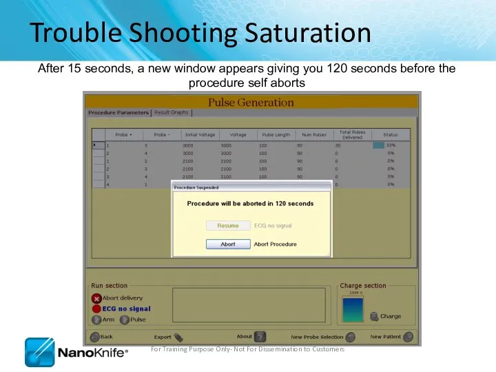
- 93. Trouble Shooting Saturation After 15 seconds, a new window appears giving you 120 seconds before the
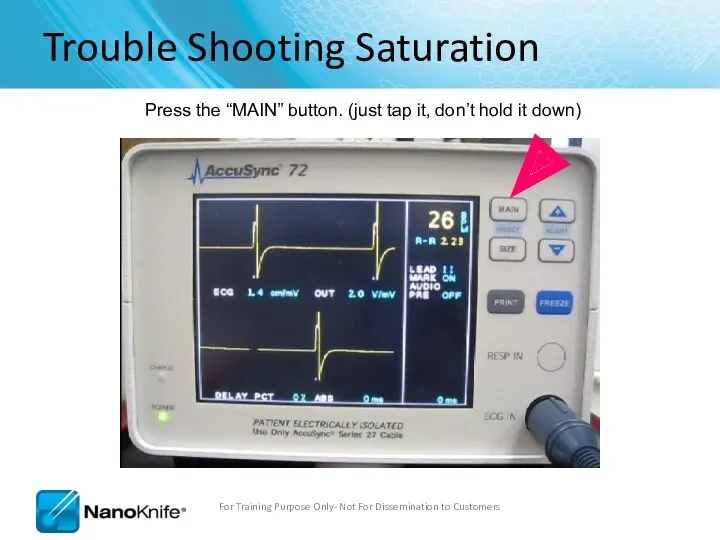
- 94. Trouble Shooting Saturation Press the “MAIN” button. (just tap it, don’t hold it down) For Training
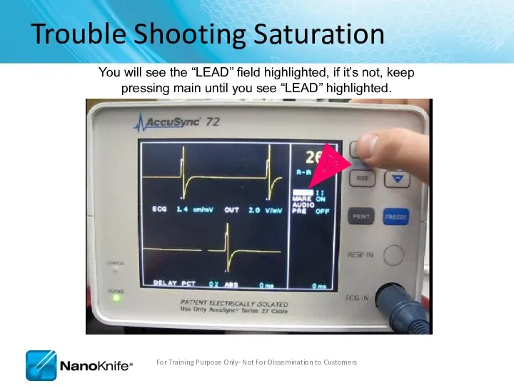
- 95. Trouble Shooting Saturation You will see the “LEAD” field highlighted, if it’s not, keep pressing main
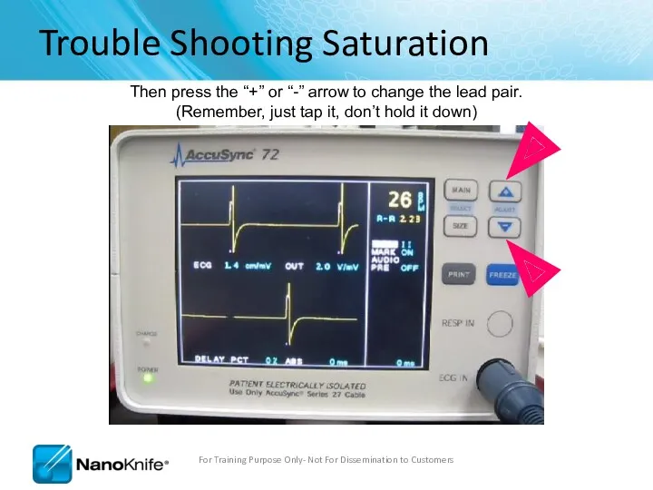
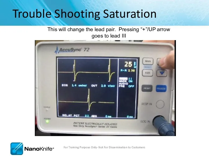
- 96. Trouble Shooting Saturation Then press the “+” or “-” arrow to change the lead pair. (Remember,
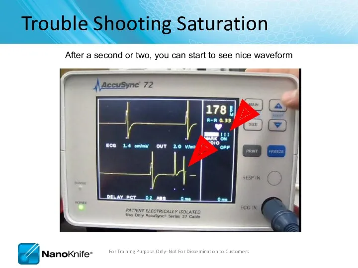
- 97. Trouble Shooting Saturation This will change the lead pair. Pressing “+”/UP arrow goes to lead III
- 98. Trouble Shooting Saturation After a second or two, you can start to see nice waveform For
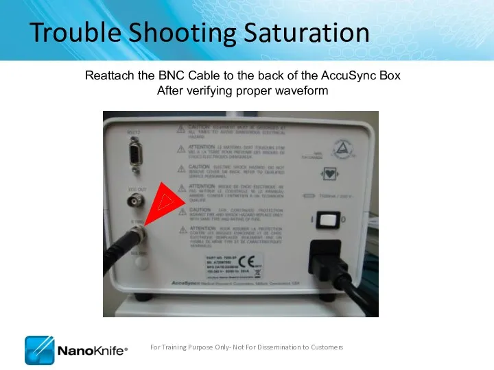
- 99. Trouble Shooting Saturation Reattach the BNC Cable to the back of the AccuSync Box After verifying
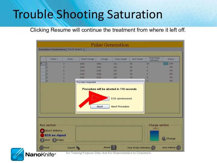
- 100. Trouble Shooting Saturation Clicking Resume will continue the treatment from where it left off. For Training
- 101. Trouble Shooting Saturation Now your treatment time will decrease! For Training Purpose Only- Not For Dissemination
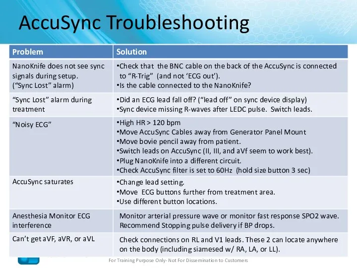
- 102. AccuSync Troubleshooting For Training Purpose Only- Not For Dissemination to Customers NanoKnife does not see sync
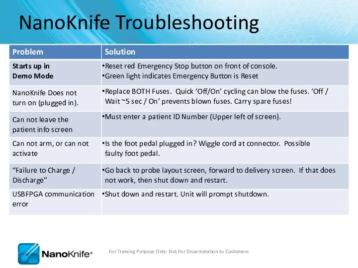
- 103. NanoKnife Troubleshooting For Training Purpose Only- Not For Dissemination to Customers NanoKnife Does not turn on
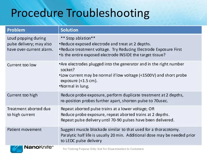
- 104. Procedure Troubleshooting Loud popping during pulse delivery; may also have over-current alarm. ** Stop ablation** Reduce
- 105. Procedure Troubleshooting Probes are migrating out during pulse delivery ** Stop ablation** Check to ensure cables
- 106. Procedure Troubleshooting Software Lags Shut down and restart system. Do this between patients to prevent this
- 107. Ohms Law V=IR V= Voltage (Volts) – “The Input” R = Resistance (Ohms) - “Tissue Dependent”
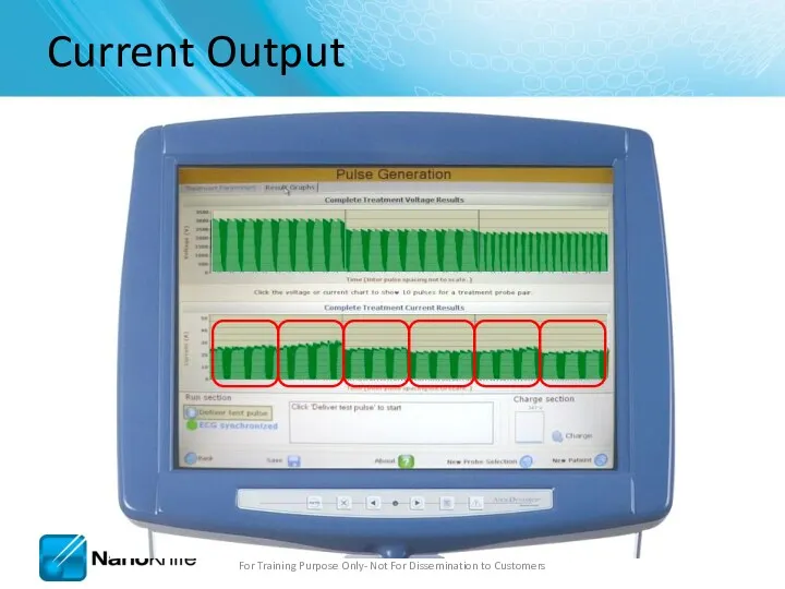
- 108. Current Output For Training Purpose Only- Not For Dissemination to Customers V = I x R
- 109. Current Output For Training Purpose Only- Not For Dissemination to Customers
- 110. Probe distance – less than 2.0cm and greater than 0.5cm Physician should aim for 1.5 –
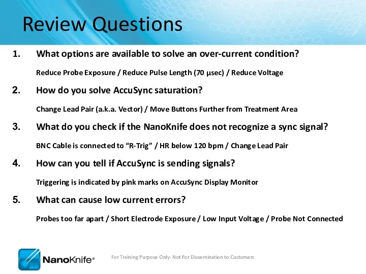
- 111. Review Questions What options are available to solve an over-current condition? Reduce Probe Exposure / Reduce
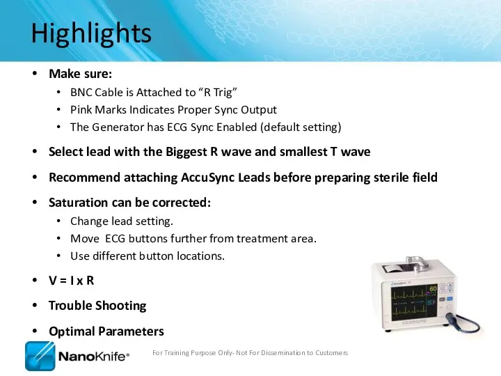
- 112. Highlights Make sure: BNC Cable is Attached to “R Trig” Pink Marks Indicates Proper Sync Output
- 114. Скачать презентацию
Agenda
What is Nanoknife?
The system
Peri-Operative Considerations
Nanoknife Treatment Planning
Software Planning
Procedure, Tips & Tricks
Clinical
Agenda
What is Nanoknife?
The system
Peri-Operative Considerations
Nanoknife Treatment Planning
Software Planning
Procedure, Tips & Tricks
Clinical

WHAT IS NANOKNIFE?
WHAT IS NANOKNIFE?
NanoKnife® Therapy: What is It?
The NanoKnife® System is indicated for the
NanoKnife® Therapy: What is It?
The NanoKnife® System is indicated for the
The function of a cell membrane is to separate the intracellular
The function of a cell membrane is to separate the intracellular
Rapid series of short, electrical pulses
Low energy direct current (LEDC)
High voltage,
Rapid series of short, electrical pulses
Low energy direct current (LEDC)
High voltage,
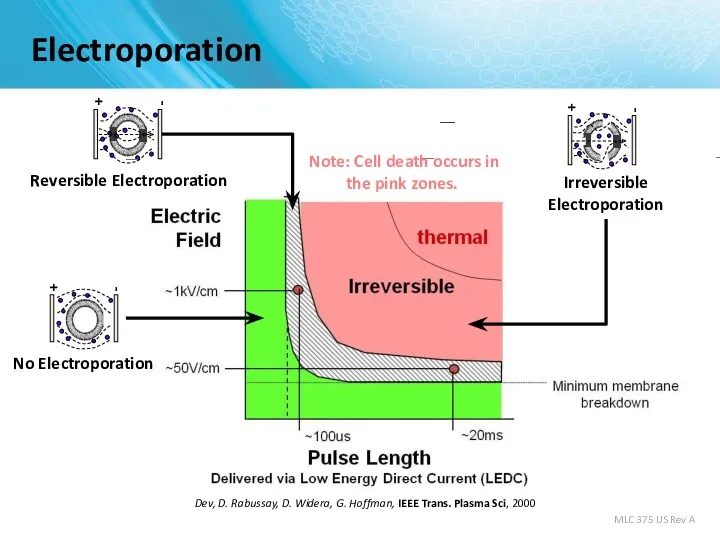
Electroporation
S. Dev, D. Rabussay, D. Widera, G. Hoffman, IEEE Trans. Plasma
Electroporation
S. Dev, D. Rabussay, D. Widera, G. Hoffman, IEEE Trans. Plasma
Uses high voltage, low energy electrical pulses to achieve tissue effect
Does
Uses high voltage, low energy electrical pulses to achieve tissue effect
Does
Images courtesy of Dr. G. Narayanan,
University of Miami – Miller School
Images courtesy of Dr. G. Narayanan, University of Miami – Miller School
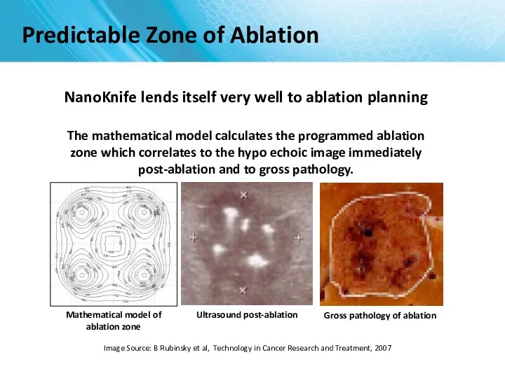
Image Source: B Rubinsky et al, Technology in Cancer Research and
Image Source: B Rubinsky et al, Technology in Cancer Research and
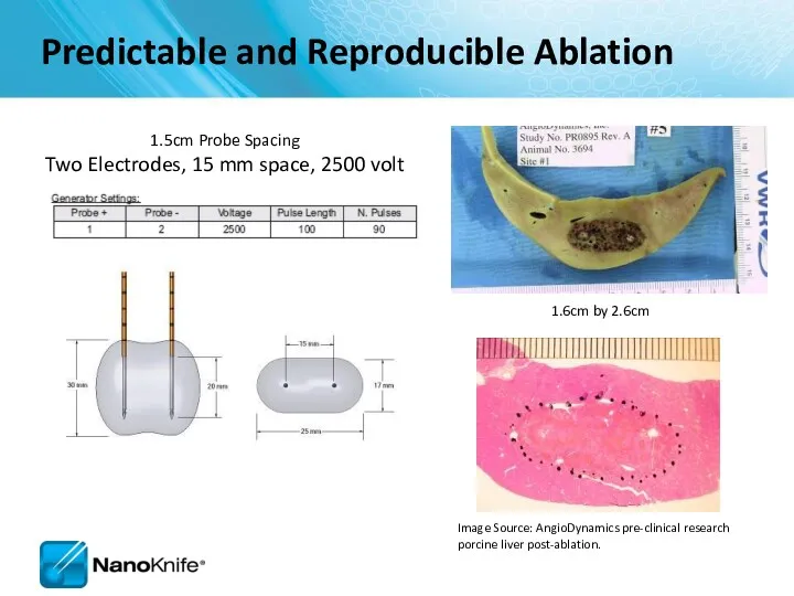
1.6cm by 2.6cm
1.5cm Probe Spacing
Two Electrodes, 15 mm space, 2500 volt
Image
1.6cm by 2.6cm
1.5cm Probe Spacing
Two Electrodes, 15 mm space, 2500 volt
Image
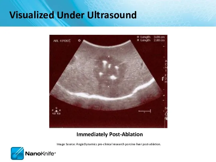
Immediately Post-Ablation
Visualized Under Ultrasound
Image Source: AngioDynamics pre-clinical research porcine liver post-ablation.
Immediately Post-Ablation
Visualized Under Ultrasound
Image Source: AngioDynamics pre-clinical research porcine liver post-ablation.

THE NANOKNIFE SYSTEM
THE NANOKNIFE SYSTEM
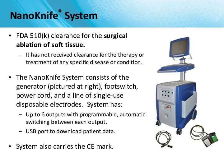
FDA 510(k) clearance for the surgical ablation of soft tissue.
It
FDA 510(k) clearance for the surgical ablation of soft tissue.
It
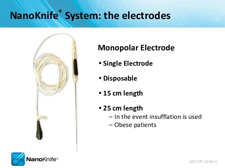
Monopolar Electrode
Single Electrode
Disposable
15 cm length
25 cm length
In the event insufflation is
Monopolar Electrode
Single Electrode
Disposable
15 cm length
25 cm length
In the event insufflation is
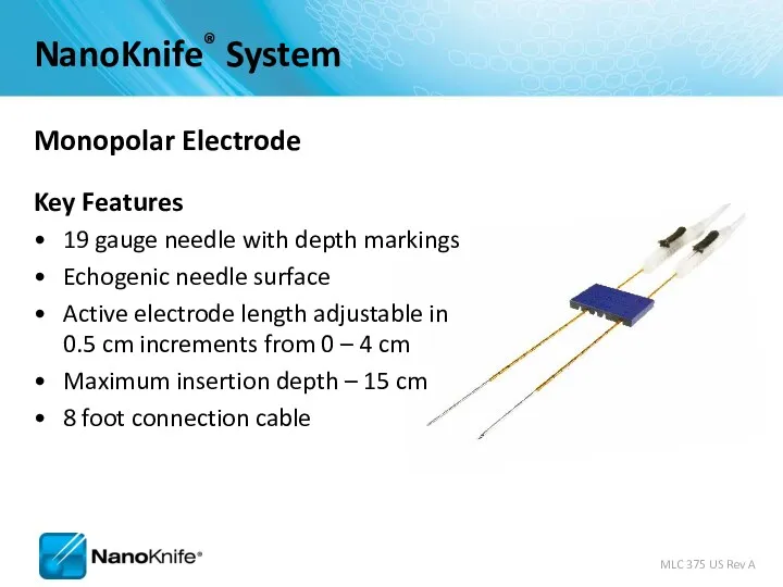
Monopolar Electrode
Key Features
19 gauge needle with depth markings
Echogenic needle surface
Active electrode
Monopolar Electrode
Key Features
19 gauge needle with depth markings
Echogenic needle surface
Active electrode
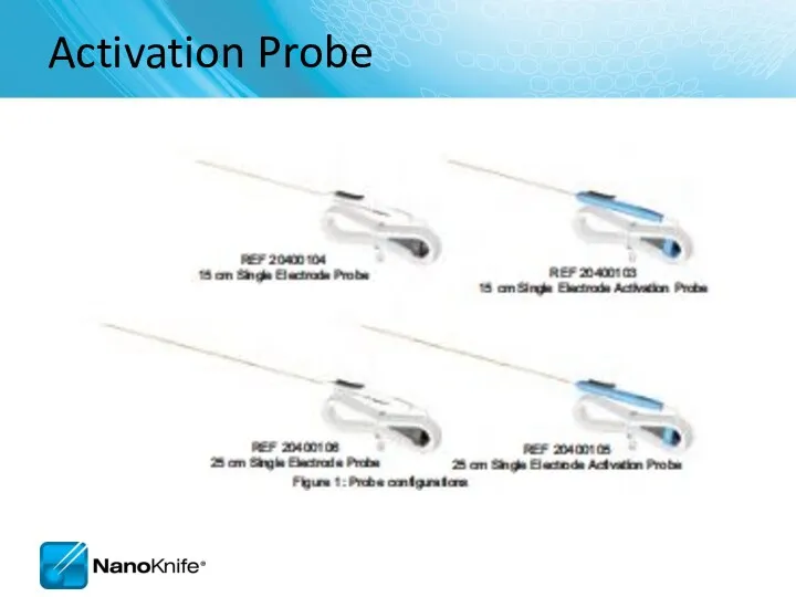
Activation Probe
Activation Probe
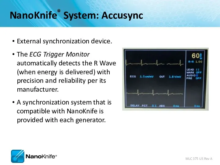
External synchronization device.
The ECG Trigger Monitor automatically detects the R Wave
External synchronization device.
The ECG Trigger Monitor automatically detects the R Wave
Energy Delivery
0
15
30
45
60
75
90
105
120
135
0
3kV
max
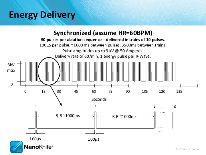
Synchronized (assume HR=60BPM)
90 pulses per ablation sequence – delivered in
Energy Delivery
0
15
30
45
60
75
90
105
120
135
0
3kV
max
Synchronized (assume HR=60BPM)
90 pulses per ablation sequence – delivered in
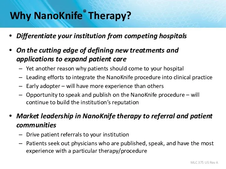
Why NanoKnife® Therapy?
Differentiate your institution from competing hospitals
On the cutting edge
Why NanoKnife® Therapy?
Differentiate your institution from competing hospitals
On the cutting edge

PERI-OPERATIVE CONSIDERATIONS
University of Louisville
PERI-OPERATIVE CONSIDERATIONS
University of Louisville
Objectives
NanoKnife Components
Room Set Up
Patient Set Up
Anesthesia Considerations
Treatment Planning
Procedural Overview
Objectives
NanoKnife Components
Room Set Up
Patient Set Up
Anesthesia Considerations
Treatment Planning
Procedural Overview
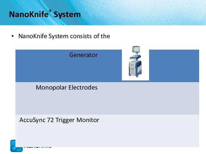
NanoKnife System consists of the
NanoKnife® System
NanoKnife System consists of the
NanoKnife® System
NANOKNIFE ROOM PREPARATION
NANOKNIFE ROOM PREPARATION
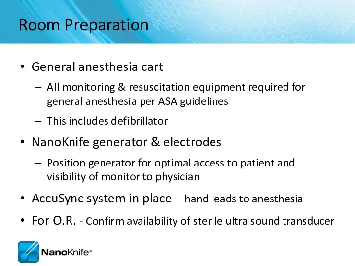
Room Preparation
General anesthesia cart
All monitoring & resuscitation equipment required for general
Room Preparation
General anesthesia cart
All monitoring & resuscitation equipment required for general
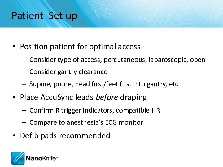
Patient Set up
Position patient for optimal access
Consider type of access; percutaneous,
Patient Set up
Position patient for optimal access
Consider type of access; percutaneous,
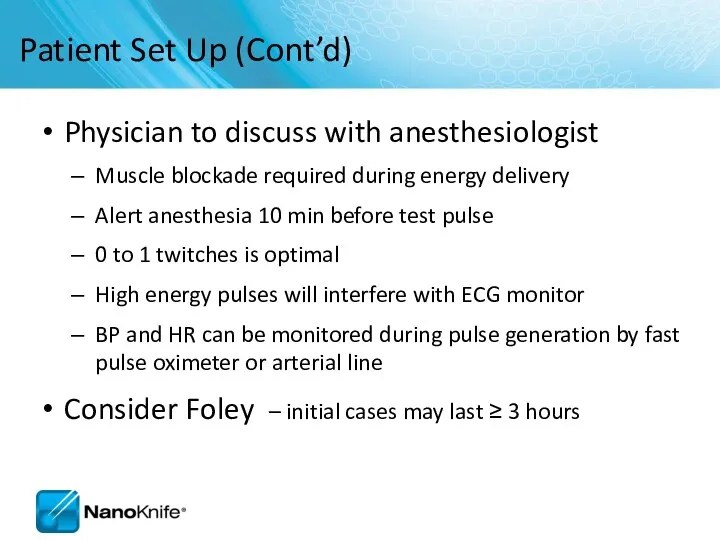
Patient Set Up (Cont’d)
Physician to discuss with anesthesiologist
Muscle blockade required
Patient Set Up (Cont’d)
Physician to discuss with anesthesiologist
Muscle blockade required
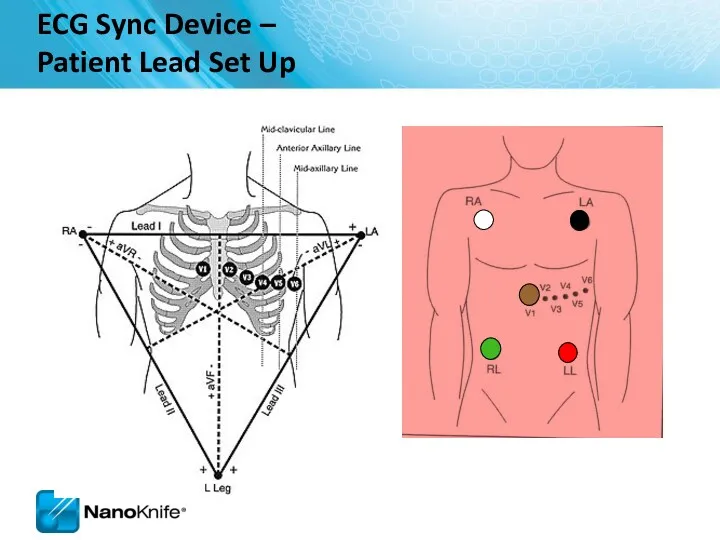
ECG Sync Device –
Patient Lead Set Up
ECG Sync Device –
Patient Lead Set Up
Pink dots indicate
R-wave output.
Set delay to zero.
Lead III is selected in
Pink dots indicate
R-wave output.
Set delay to zero.
Lead III is selected in

PROCEDURAL OVERVIEW
PROCEDURAL OVERVIEW
Procedure Steps – Part I
Set-up AccuSync - select best lead vector
Determine
Procedure Steps – Part I
Set-up AccuSync - select best lead vector
Determine
Procedure Steps – Part II
Update treatment planning software with actual inter-probe
Procedure Steps – Part II
Update treatment planning software with actual inter-probe
SOFTWARE PLANNING
SOFTWARE PLANNING

Getting Started
Confirm the updated software is in place during start
Getting Started
Confirm the updated software is in place during start

Information Screen
There are five sections in the Information screen
1
2
3
4
5
Information Screen
There are five sections in the Information screen
1
2
3
4
5
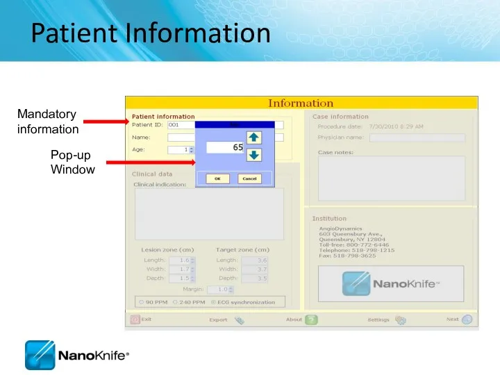
Patient Information
Patient Information
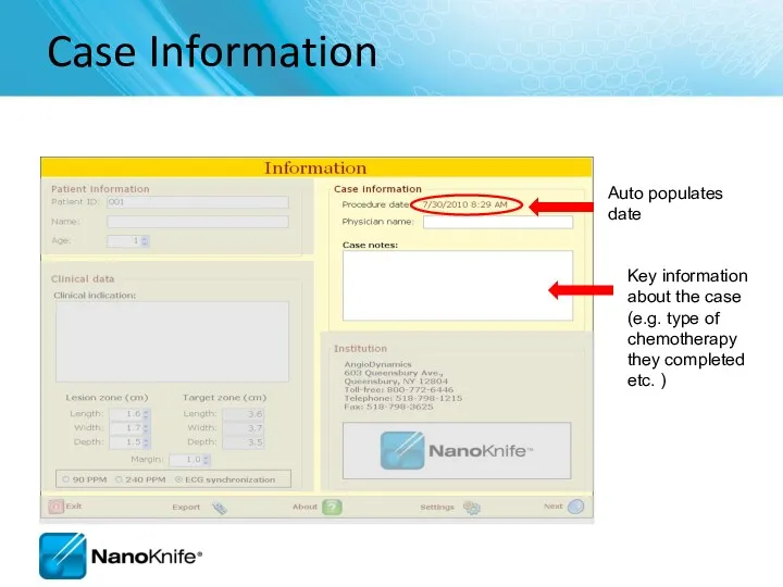
Case Information
Key information about the case (e.g. type of chemotherapy they
Case Information
Key information about the case (e.g. type of chemotherapy they
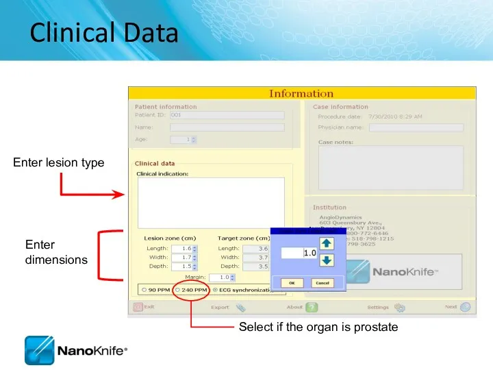
Clinical Data
Enter lesion type
Enter
dimensions
Clinical Data
Enter lesion type
Enter
dimensions
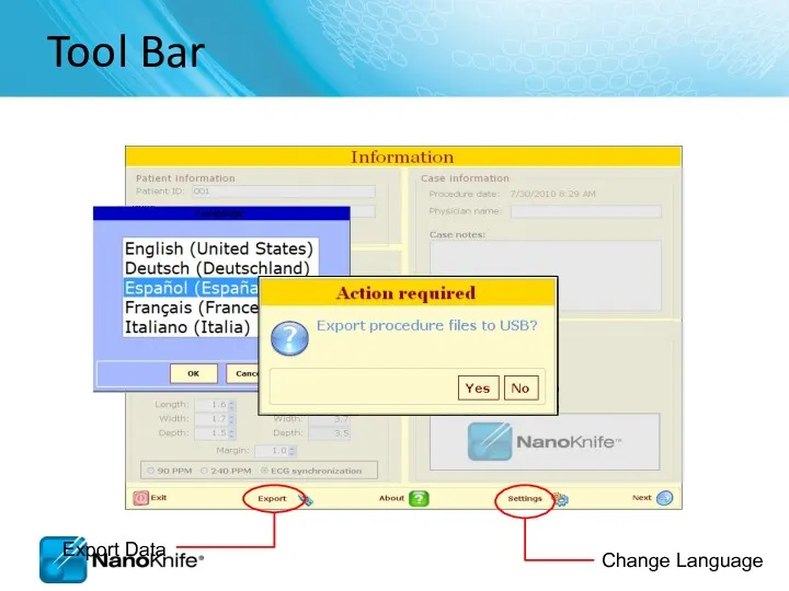
Tool Bar
Tool Bar
2.1.0 versus 2.2.0
Information Screen
New pop-up window when selecting age, lesion
2.1.0 versus 2.2.0
Information Screen
New pop-up window when selecting age, lesion
Objective:
Accurately Correlate 3 Phases
Probes in Tissue
Probes on Grid Plot
Probes
Objective:
Accurately Correlate 3 Phases
Probes in Tissue
Probes on Grid Plot
Probes
Labeling Length,
Width, Depth
Width and Depth Orientation Change with Anatomical
Labeling Length,
Width, Depth
Width and Depth Orientation Change with Anatomical
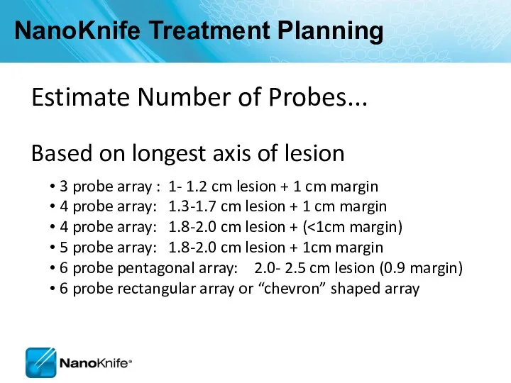
NanoKnife Treatment Planning
Estimate Number of Probes...
Based on longest axis of lesion
NanoKnife Treatment Planning
Estimate Number of Probes...
Based on longest axis of lesion
Electrode Positioning
Flexible – customize to lesion size using 2 to
Electrode Positioning
Flexible – customize to lesion size using 2 to
Probe Selection Screen
Probe Selection Screen
Probe Selection Screen
Probe Selection Screen
2.1.0 versus 2.2.0
Probe Selection Screen
RFID probes identified
Activator probe is
2.1.0 versus 2.2.0
Probe Selection Screen
RFID probes identified
Activator probe is
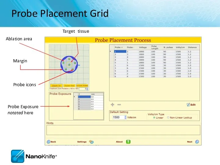
Probe Placement Grid
Probe icons
Probe Exposure notated here
Probe Placement Grid
Probe icons
Probe Exposure notated here
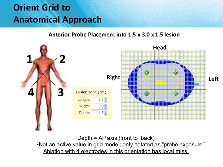
Head
Orient Grid to
Anatomical Approach
Anterior Probe Placement into 1.5 x 3.0
Head
Orient Grid to
Anatomical Approach
Anterior Probe Placement into 1.5 x 3.0
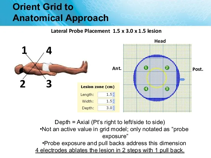
Orient Grid to
Anatomical Approach
Head
Lateral Probe Placement 1.5 x 3.0 x
Orient Grid to
Anatomical Approach
Head
Lateral Probe Placement 1.5 x 3.0 x
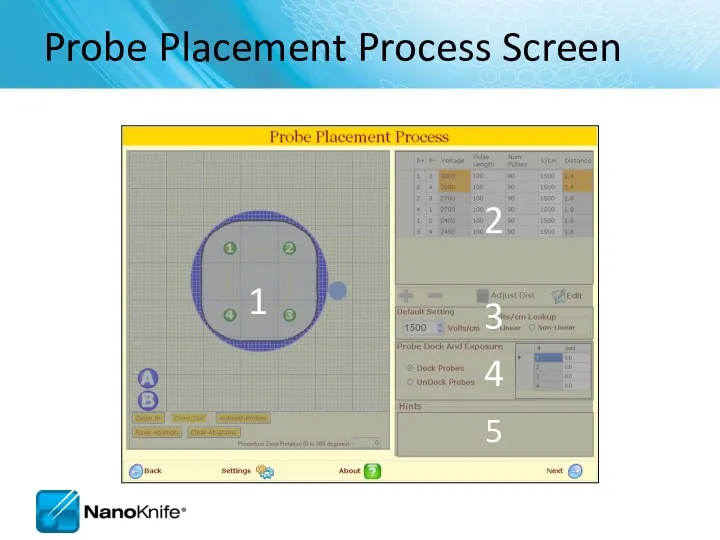
Probe Placement Process Screen
1
2
3
4
5
Probe Placement Process Screen
1
2
3
4
5
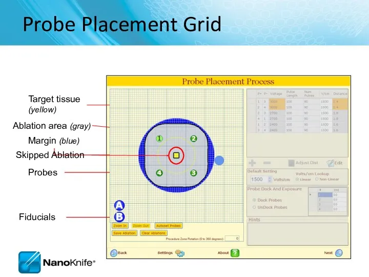
Probe Placement Grid
Probes
Target tissue
(yellow)
Ablation area (gray)
Fiducials
Skipped Ablation
Probe Placement Grid
Probes
Target tissue
(yellow)
Ablation area (gray)
Fiducials
Skipped Ablation
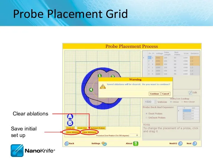
Probe Placement Grid
Save initial set up
Clear ablations
Probe Placement Grid
Save initial set up
Clear ablations
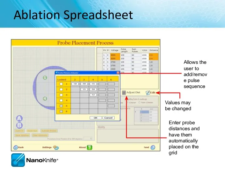
Ablation Spreadsheet
Enter probe distances and have them automatically placed on the
Ablation Spreadsheet
Enter probe distances and have them automatically placed on the
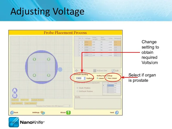
Adjusting Voltage
Change setting to obtain required Volts/cm
Adjusting Voltage
Change setting to obtain required Volts/cm
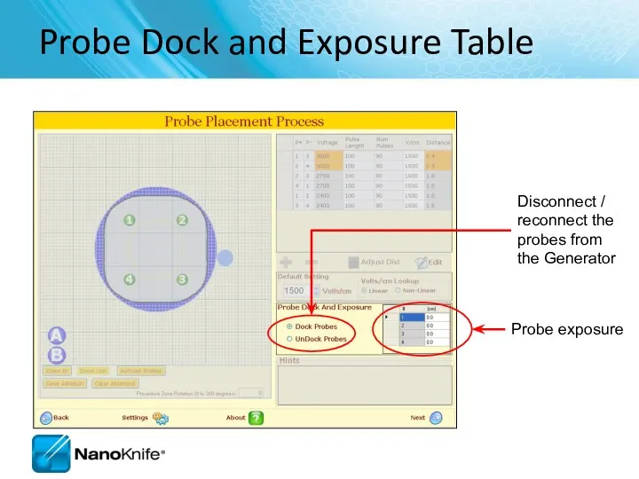
Probe Dock and Exposure Table
Disconnect / reconnect the probes from
Probe Dock and Exposure Table
Disconnect / reconnect the probes from
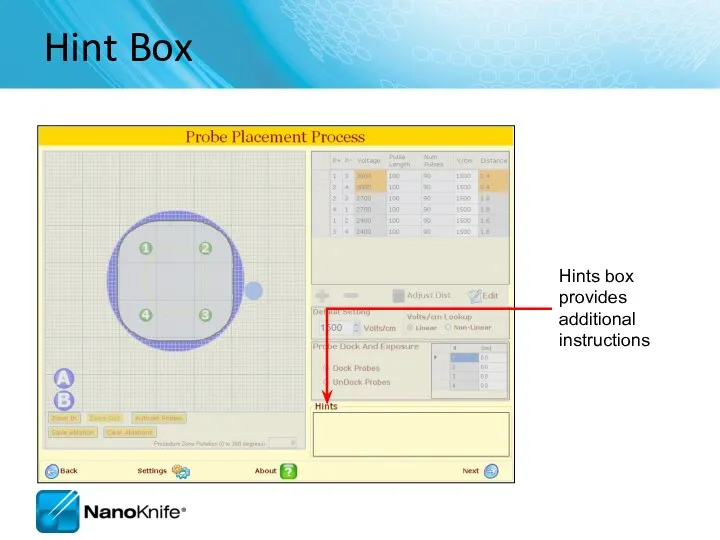
Hint Box
Hints box provides additional instructions
Hint Box
Hints box provides additional instructions
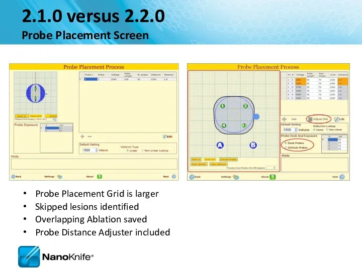
2.1.0 versus 2.2.0
Probe Placement Screen
Probe Placement Grid is larger
Skipped lesions
2.1.0 versus 2.2.0
Probe Placement Screen
Probe Placement Grid is larger
Skipped lesions
Pulse Generation Screen
Where the ablation is delivered
Pulse Generation Screen
Where the ablation is delivered
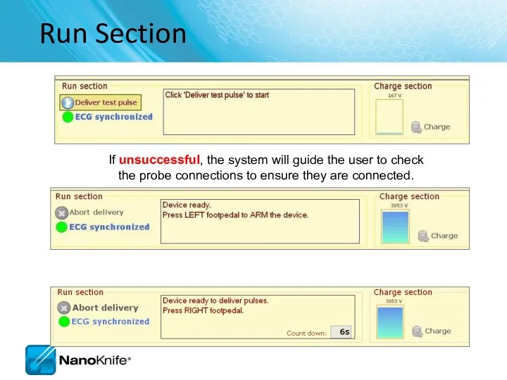
If unsuccessful, the system will guide the user to check the
If unsuccessful, the system will guide the user to check the
2.1.0 versus 2.2.0
Pulse Generation Screen
Different progress bar
Export button available
2.1.0 versus 2.2.0
Pulse Generation Screen
Different progress bar
Export button available
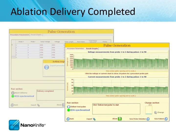
Ablation Delivery Completed
Ablation Delivery Completed
2.1.0 versus 2.2.0
Pulse Generation Completed Ablation and Graph Screen
Export button
2.1.0 versus 2.2.0
Pulse Generation Completed Ablation and Graph Screen
Export button
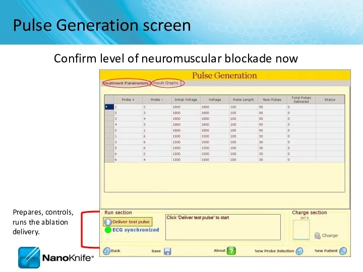
Pulse Generation screen
Confirm level of neuromuscular blockade now
Pulse Generation screen
Confirm level of neuromuscular blockade now
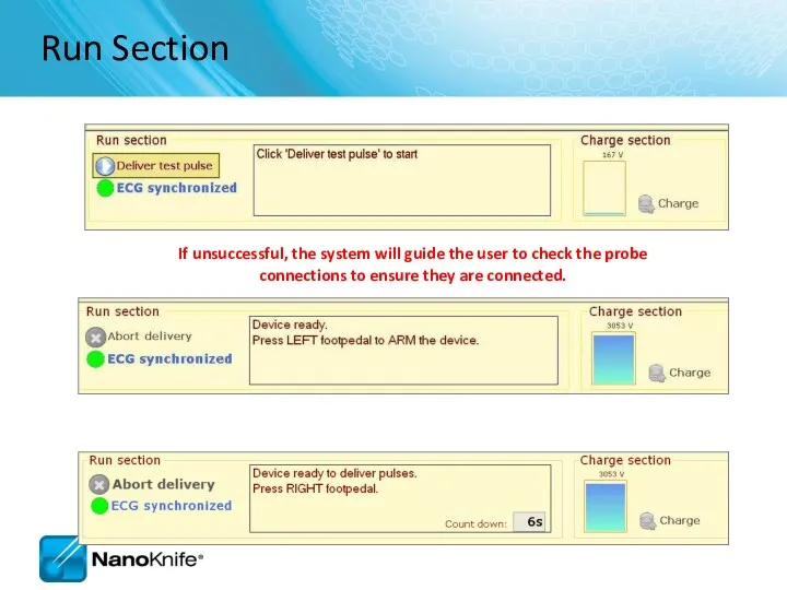
Run Section
If unsuccessful, the system will guide the user to check
Run Section
If unsuccessful, the system will guide the user to check
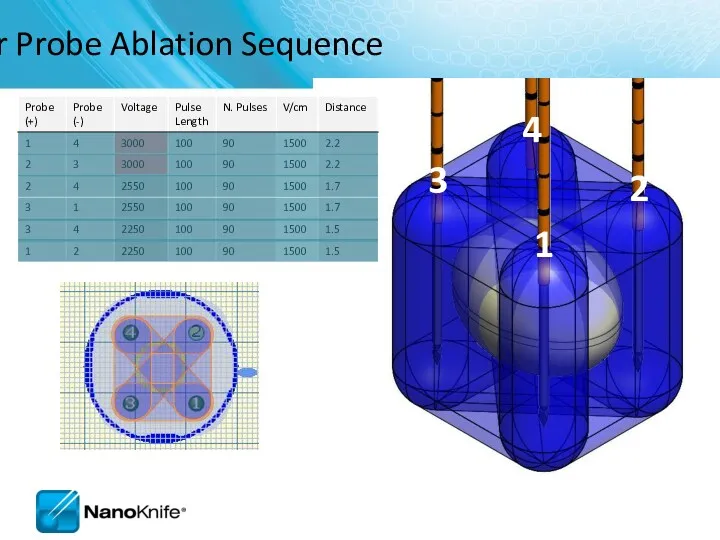
Four Probe Ablation Sequence
1
2
3
4
Four Probe Ablation Sequence
1
2
3
4
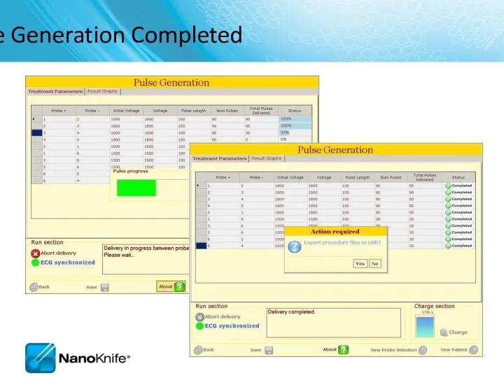
Pulse Generation Completed
Pulse Generation Completed
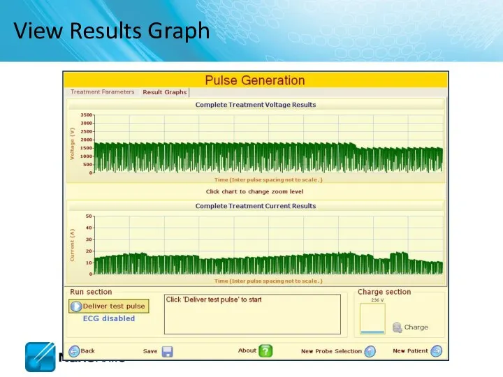
View Results Graph
View Results Graph
NANOKNIFE TREATMENT PLANNING –
PRACTICAL CONSIDERATIONS
USING 2.1.0 LESION ESTIMATOR
For Training Purpose
NANOKNIFE TREATMENT PLANNING –
PRACTICAL CONSIDERATIONS
USING 2.1.0 LESION ESTIMATOR
For Training Purpose
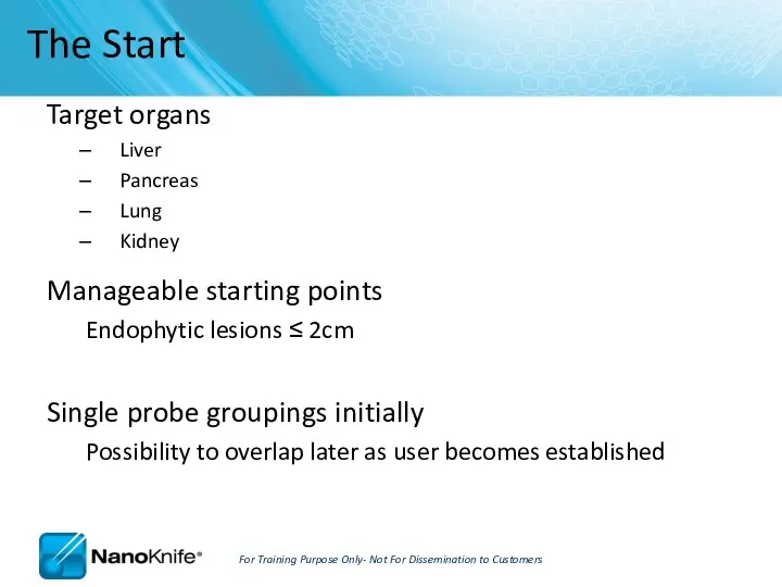
Target organs
Liver
Pancreas
Lung
Kidney
Manageable starting points
Endophytic lesions ≤ 2cm
Single probe groupings
Target organs
Liver
Pancreas
Lung
Kidney
Manageable starting points
Endophytic lesions ≤ 2cm
Single probe groupings
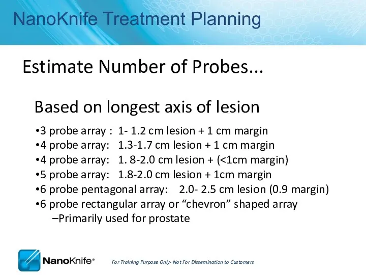
NanoKnife Treatment Planning
Estimate Number of Probes...
Based on longest axis of
NanoKnife Treatment Planning
Estimate Number of Probes...
Based on longest axis of
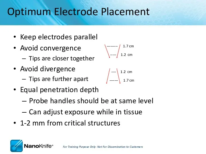
Keep electrodes parallel
Avoid convergence
Tips are closer together
Avoid divergence
Tips
Keep electrodes parallel
Avoid convergence
Tips are closer together
Avoid divergence
Tips
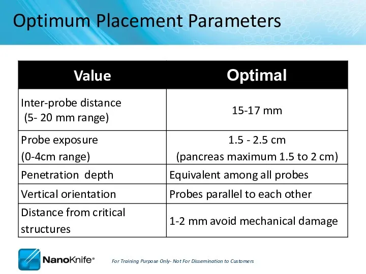
Optimum Placement Parameters
For Training Purpose Only- Not For Dissemination to
Optimum Placement Parameters
For Training Purpose Only- Not For Dissemination to
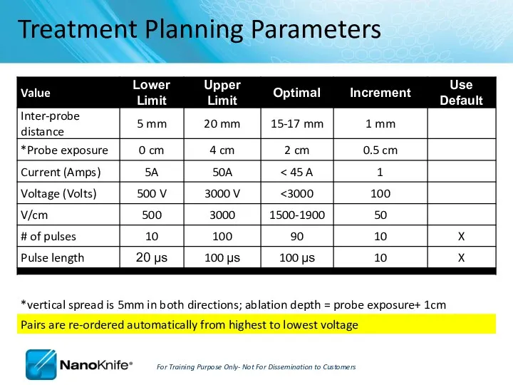
Treatment Planning Parameters
For Training Purpose Only- Not For Dissemination to Customers
Treatment Planning Parameters
For Training Purpose Only- Not For Dissemination to Customers
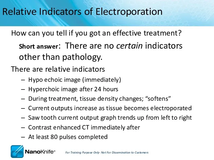
How can you tell if you got an effective treatment?
Short answer:
How can you tell if you got an effective treatment?
Short answer:
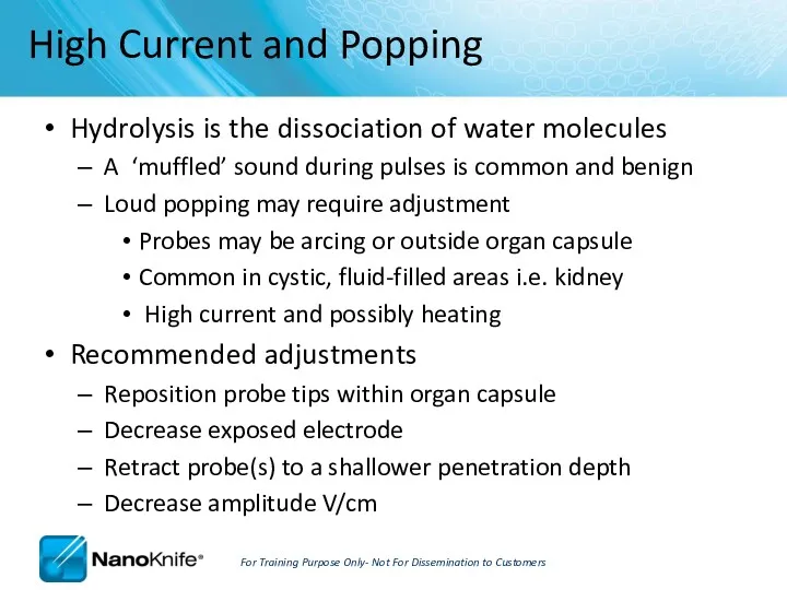
Hydrolysis is the dissociation of water molecules
A ‘muffled’ sound during
Hydrolysis is the dissociation of water molecules
A ‘muffled’ sound during
It’s always a good idea to…
RE-IMAGE when probe placement, inter-probe
It’s always a good idea to…
RE-IMAGE when probe placement, inter-probe
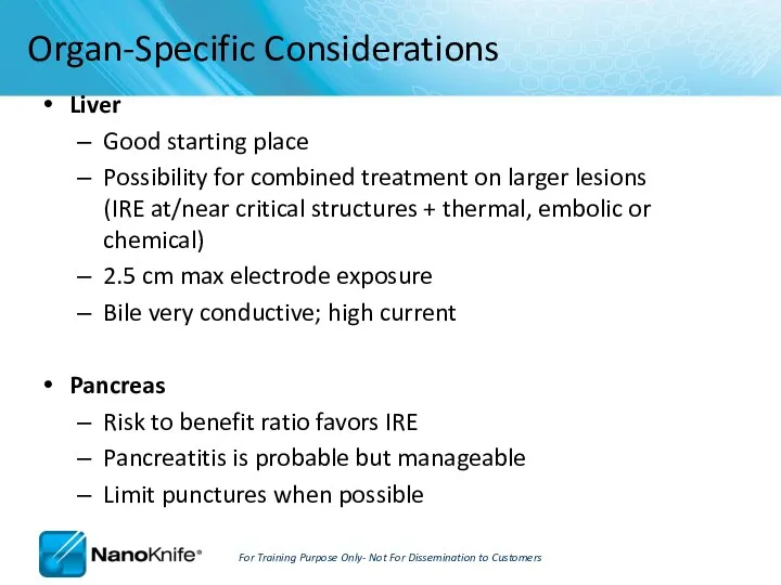
Liver
Good starting place
Possibility for combined treatment on larger lesions (IRE
Liver
Good starting place
Possibility for combined treatment on larger lesions (IRE

Kidney
Very conductive ( draws 20-23 Amps)
2-2.5 max probe exposure
Pulses into
Kidney
Very conductive ( draws 20-23 Amps)
2-2.5 max probe exposure
Pulses into
Procedure Tips, Tricks, and Troubleshooting
September 16, 2010
Procedure Tips, Tricks, and Troubleshooting
September 16, 2010
Learning Objectives
NanoKnife Set-Up
AccuSync 72 Set-Up
ECG Synchronized Pulse Delivery
Proper Sync Function
ECG Sync
Learning Objectives
NanoKnife Set-Up
AccuSync 72 Set-Up
ECG Synchronized Pulse Delivery
Proper Sync Function
ECG Sync
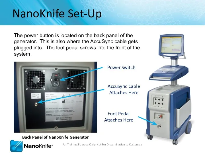
NanoKnife Set-Up
The power button is located on the back panel of
NanoKnife Set-Up
The power button is located on the back panel of
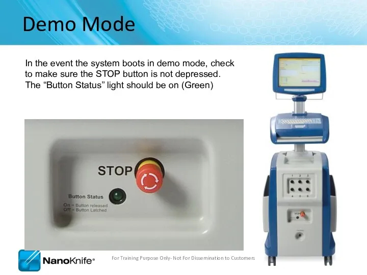
Demo Mode
In the event the system boots in demo mode, check
Demo Mode
In the event the system boots in demo mode, check
Power Switch
Patient Leads
AccuSync Set-Up
For Training Purpose Only- Not For Dissemination
Power Switch
Patient Leads
AccuSync Set-Up
For Training Purpose Only- Not For Dissemination
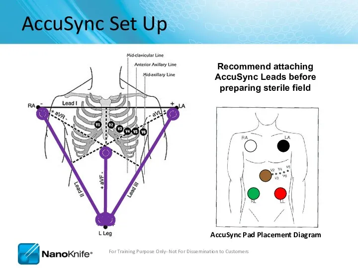
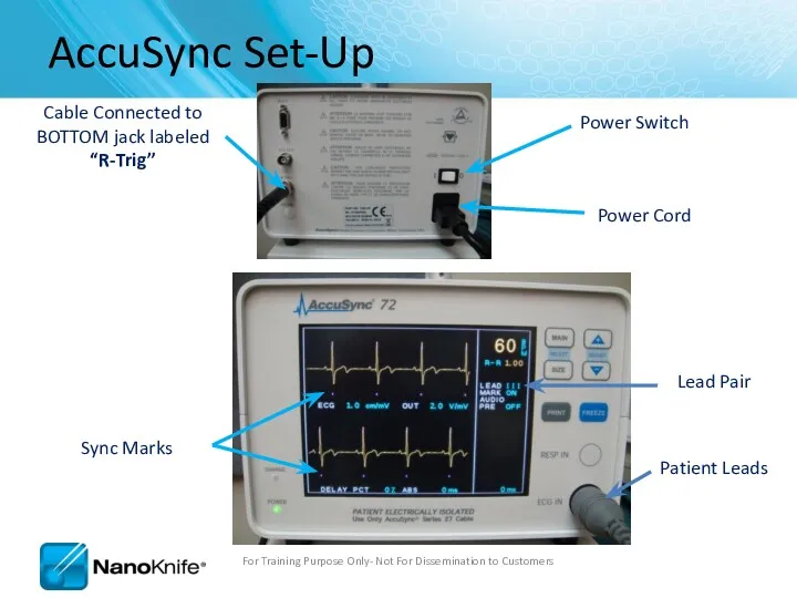
AccuSync Set Up
For Training Purpose Only- Not For Dissemination to Customers
Recommend
AccuSync Set Up
For Training Purpose Only- Not For Dissemination to Customers
Recommend
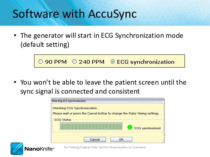
Software with AccuSync
The generator will start in ECG Synchronization mode (default
Software with AccuSync
The generator will start in ECG Synchronization mode (default
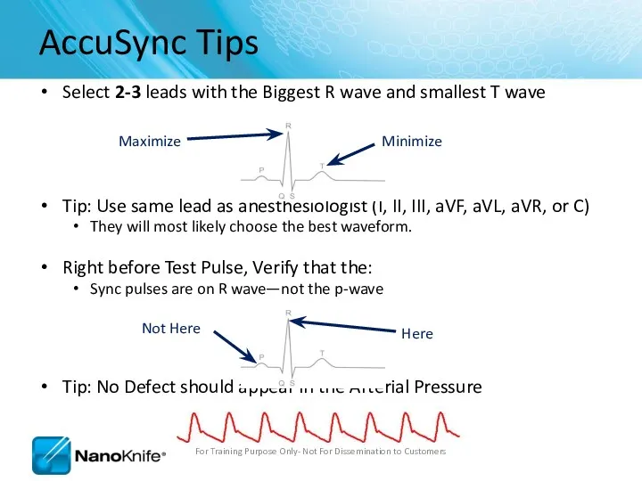
Select 2-3 leads with the Biggest R wave and smallest T
Select 2-3 leads with the Biggest R wave and smallest T
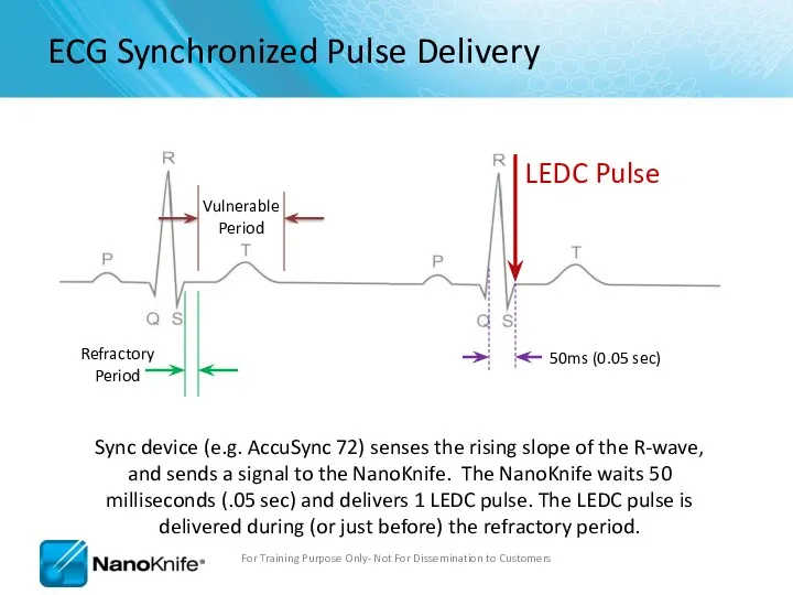
ECG Synchronized Pulse Delivery
Sync device (e.g. AccuSync 72) senses the rising
ECG Synchronized Pulse Delivery
Sync device (e.g. AccuSync 72) senses the rising
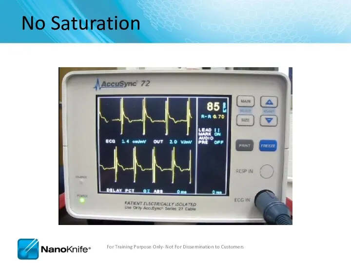
No Saturation
For Training Purpose Only- Not For Dissemination to Customers
No Saturation
For Training Purpose Only- Not For Dissemination to Customers
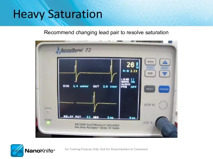
Heavy Saturation
Recommend changing lead pair to resolve saturation
For Training Purpose Only-
Heavy Saturation
Recommend changing lead pair to resolve saturation
For Training Purpose Only-
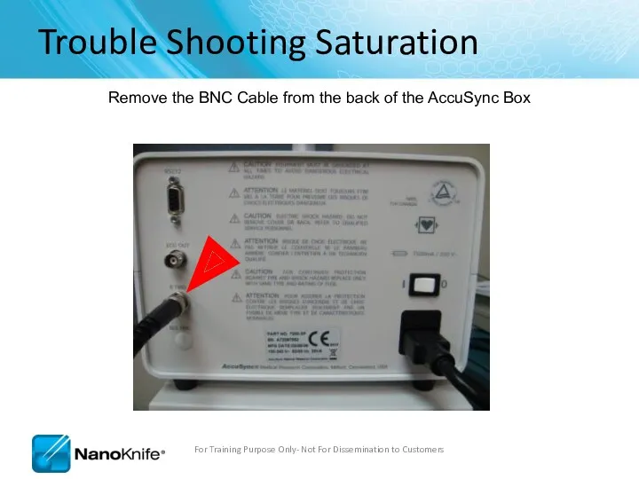
Trouble Shooting Saturation
Remove the BNC Cable from the back of the
Trouble Shooting Saturation
Remove the BNC Cable from the back of the
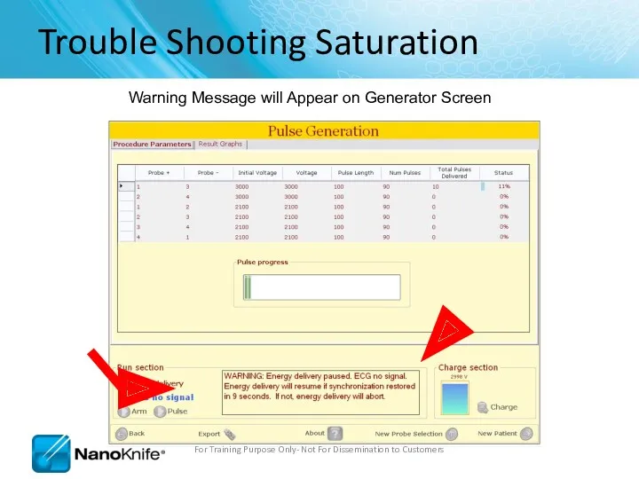
Trouble Shooting Saturation
Warning Message will Appear on Generator Screen
For Training Purpose
Trouble Shooting Saturation
Warning Message will Appear on Generator Screen
For Training Purpose
Trouble Shooting Saturation
After 15 seconds, a new window appears giving you
Trouble Shooting Saturation
After 15 seconds, a new window appears giving you
Trouble Shooting Saturation
Press the “MAIN” button. (just tap it, don’t hold
Trouble Shooting Saturation
Press the “MAIN” button. (just tap it, don’t hold
Trouble Shooting Saturation
You will see the “LEAD” field highlighted, if it’s
Trouble Shooting Saturation
You will see the “LEAD” field highlighted, if it’s
Trouble Shooting Saturation
Then press the “+” or “-” arrow to change
Trouble Shooting Saturation
Then press the “+” or “-” arrow to change
Trouble Shooting Saturation
This will change the lead pair. Pressing “+”/UP arrow
Trouble Shooting Saturation
This will change the lead pair. Pressing “+”/UP arrow
Trouble Shooting Saturation
After a second or two, you can start to
Trouble Shooting Saturation
After a second or two, you can start to
Trouble Shooting Saturation
Reattach the BNC Cable to the back of the
Trouble Shooting Saturation
Reattach the BNC Cable to the back of the
Trouble Shooting Saturation
Clicking Resume will continue the treatment from where it
Trouble Shooting Saturation
Clicking Resume will continue the treatment from where it
Trouble Shooting Saturation
Now your treatment time will decrease!
For Training Purpose Only-
Trouble Shooting Saturation
Now your treatment time will decrease!
For Training Purpose Only-
AccuSync Troubleshooting
For Training Purpose Only- Not For Dissemination to Customers
NanoKnife does
AccuSync Troubleshooting
For Training Purpose Only- Not For Dissemination to Customers
NanoKnife does
NanoKnife Troubleshooting
For Training Purpose Only- Not For Dissemination to Customers
NanoKnife Does
NanoKnife Troubleshooting
For Training Purpose Only- Not For Dissemination to Customers
NanoKnife Does
Procedure Troubleshooting
Loud popping during pulse delivery; may also have over-current
Procedure Troubleshooting
Loud popping during pulse delivery; may also have over-current
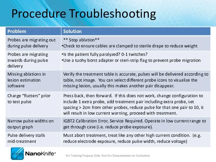
Procedure Troubleshooting
Probes are migrating out during pulse delivery
** Stop ablation**
Check
Procedure Troubleshooting
Probes are migrating out during pulse delivery
** Stop ablation**
Check
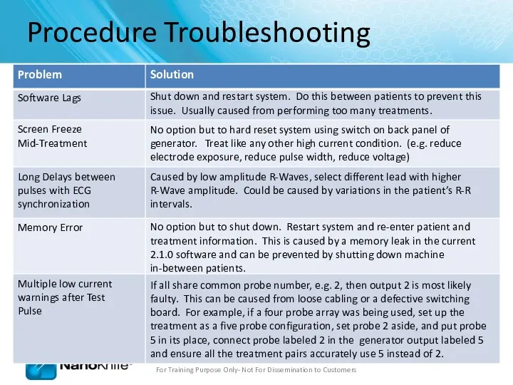
Procedure Troubleshooting
Software Lags
Shut down and restart system. Do this between
Procedure Troubleshooting
Software Lags
Shut down and restart system. Do this between
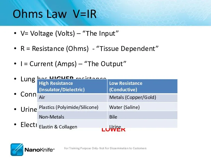
Ohms Law V=IR
V= Voltage (Volts) – “The Input”
R = Resistance (Ohms)
Ohms Law V=IR
V= Voltage (Volts) – “The Input”
R = Resistance (Ohms)
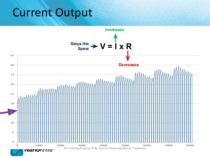
Current Output
For Training Purpose Only- Not For Dissemination to Customers
V =
Current Output
For Training Purpose Only- Not For Dissemination to Customers
V =
Current Output
For Training Purpose Only- Not For Dissemination to Customers
Current Output
For Training Purpose Only- Not For Dissemination to Customers
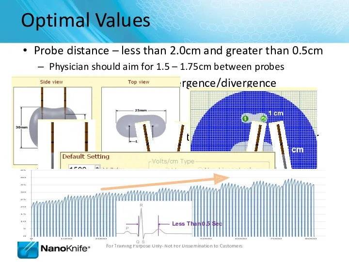
Probe distance – less than 2.0cm and greater than 0.5cm
Physician
Probe distance – less than 2.0cm and greater than 0.5cm
Physician
Review Questions
What options are available to solve an over-current condition?
Reduce Probe
Review Questions
What options are available to solve an over-current condition?
Reduce Probe
Highlights
Make sure:
BNC Cable is Attached to “R Trig”
Pink Marks Indicates
Highlights
Make sure:
BNC Cable is Attached to “R Trig”
Pink Marks Indicates
 Медицинское обеспечение детей и подростков в образовательных организациях
 Рефлекторные синдромы шейного остеохондроза
 Урогенитальный хламидиоз
 Эндокриндік жүйе
 Темір жетіспеушілік анемияның клиникалық көріністері
 Гастроэзофагеальная рефлюксная болезнь
 Дизайны клинических исследований
 Гирудотерапия на современном этапе
 Первая медицинская помощь при отравлении химическими веществами. Наиболее характерные признаки химического отравления
 Өт шығару жолдарының ауруларымен балаларда диспансерлік бақылауды ұйымдастыру
 Антиаритмические препараты. Неотложная помощь при тахи-брадиаритмиях
 Опухоли зрительного нерва
 Занятие для детей по оказанию первой помощи при ИМ и МИ
 Причины и предрасполагающие факторы к возникновению рахита
 Заболевания век, слезных органов, орбиты и конъюнктивы
 Сурфактантная терапия
 Микрорефлексотерапия пациента с хронической обструктивной болезнью легких в стадии обострения
 Инфузионная терапия
 Исследование защитных свойств зубных паст
 Первичные бесполостные морфологические признаки кожи
 Методы клинической биохимии. Контроль качества лабораторных исследований
 Будова та розвиток чоловічих і жіночих статевих органів
 Синдром гиперстимуляции яичников, как процедуры ЭКО
 Первая медицинская помощь при травмах и повреждениях верхних и нижних конечностей. Занятие №2
 Очаговые поражения легких: дифференциальная диагностика
 Gynecological infections and abnormalities
 Предварительные и периодические медицинские осмотры работников
 Бейімделу физиологиясы