- Types of Pacemakers

Содержание
- 2. Disclosures This presentation is provided for general educational purposes only and should not be considered the
- 3. Objectives Explain the different types of pacemakers and the NBG Code Identify the components of a
- 4. TYPES OF PACEMAKERS
- 5. Single Chamber System One lead Atrium Ventricle (most common) May be used for patients in chronic
- 6. Dual Chamber System Two leads One lead implanted in the atrium One lead implanted in the
- 7. Dual Chamber Pacemaker RV Lead at the Apex RA Lead in Appendage
- 8. Triple Chamber System Three Leads: Right Atrium Right Ventricle Left Ventricle (via the Coronary Sinus vein)
- 9. NBG Code – The Usual Pacing Modes Examples of pacing modes which are typically programmed: DDD
- 10. Knowledge Checkpoint What type of pacemaker is this?
- 11. Knowledge Checkpoint What does VVIR mode mean?
- 12. Key Learning Points There are three types of pacemakers Important to identify which one the patient
- 13. COMPONENTS OF THE PACEMAKER SYSTEM
- 14. Implantable Pacemaker Circuit Implantable pulse generator (IPG): Battery Circuitry Connector(s) Leads or wires Cathode (negative electrode)
- 15. Lithium-Iiodine Battery 2.8 V BOL Longevity Dependent on impedance and output Ranges from 6-12 years Circuitry
- 16. Leads are Insulated Wires Deliver electrical impulses from the pulse generator to the heart Sense cardiac
- 17. Lead Polarity Unipolar leads May have a smaller diameter lead body than bipolar leads May exhibit
- 18. Unipolar Pacing System The lead has only one electrode (the cathode) at the tip The pacemaker
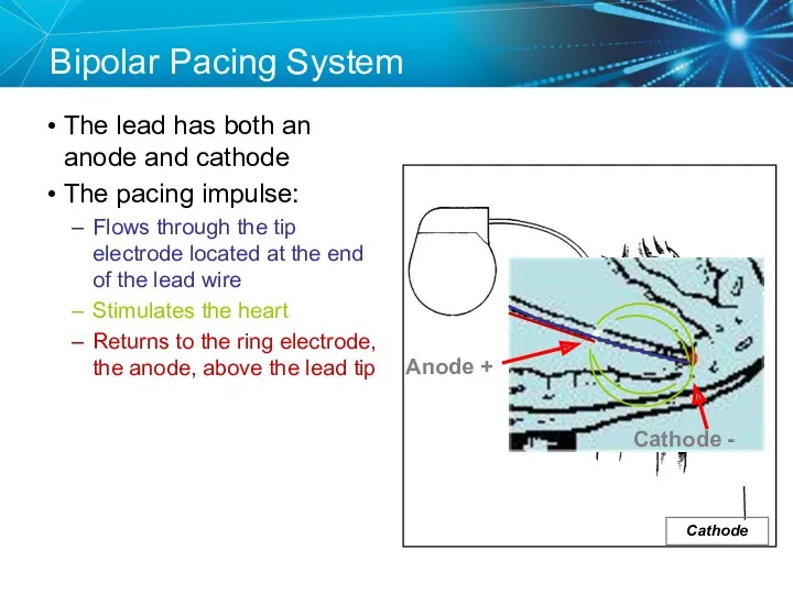
- 19. Anode Bipolar Pacing System The lead has both an anode and cathode The pacing impulse: Flows
- 20. Transvenous Leads Passive fixation (tined) The tines become lodged in the trabeculae of the apex or
- 21. Epicardial Leads Leads applied directly to the surface of the heart Utilized in pediatric patients and
- 22. Lead Insulators Silicone insulated leads Inert Biocompatible Biostable Repairable with medical adhesive Historically very reliable Polyurethane
- 23. Knowledge Checkpoint Where is the anode located in bipolar pacing? C A B D Tip Electrode
- 24. Key Learning Points The pacemaker circuit consists of the leads, device, and tissue Modern leads are
- 25. ELECTRICAL CONCEPTS IN PACEMAKERS
- 26. Voltage Voltage is the force, or “push,” that causes electrons to move through a circuit In
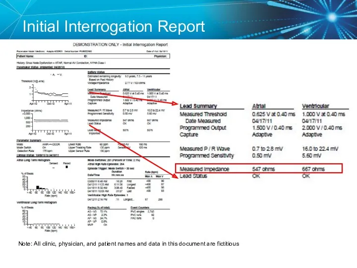
- 27. Initial Interrogation Report Note: All clinic, physician, and patient names and data in this document are
- 28. Voltage
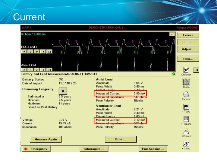
- 29. Current The flow of electrons through a completed circuit In a pacing system, current is: Measured
- 30. Current
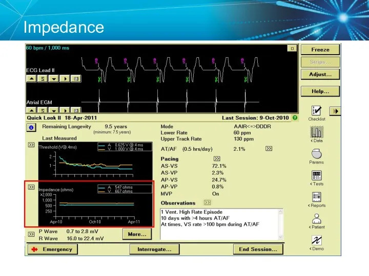
- 31. Impedance The opposition to current flow In a pacing system, impedance is: Measured in ohms (Ω)
- 32. Initial Interrogation Report Note: All clinic, physician, and patient names and data in this document are
- 33. Impedance
- 34. Summary Voltage, Current, and Impedance Voltage: The force moving the current (V) In pacemakers it is
- 35. Ohm’s Law Describes the relationship between voltage, current, and resistance (impedance) V = I X R
- 36. Ohm’s law tells us: If the impedance (R) remains constant, and the voltage decreases, the current
- 37. Knowledge Checkpoint What is the delivered current from the Atrial Lead?
- 38. Key Learning Points Know where to find the voltage and impedance on the programmer and report
- 39. TESTING THE PACEMAKER CIRCUIT
- 40. Typical Lead Impedance Range Most important that lead impedance is stable over the lifetime of the
- 41. Lead Impedance Values Electrical Analogies Normal resistance – friction caused by the hose and nozzle Similar
- 42. Knowledge Checkpoint What would you expect to happen if a lead was fractured? A. Impedance would
- 43. High Impedance Conditions A Fractured Conductor A fractured wire can cause Impedance values to rise Current
- 44. Case Study: Clinic Visit 85 year old male with h/o pacemaker implant in 1996. Generator change
- 45. Can you identify a problem? 1st Rib-Clavicle Crush (lead fracture) Chest X Ray
- 46. Lead Fracture Lead Crush Now that you know what the problem is, How do you fix
- 47. Solutions for Lead Crush Unipolar configuration if the inner conductor is still intact Lead replacement
- 48. Knowledge Checkpoint What would you expect to happen if a lead has an insulation break? Check
- 49. Low Impedance Conditions An Insulation Break Insulation breaks can cause impedance values to fall Current drain
- 50. Case Study: Routine Follow Up A patient comes in for routine follow up and you notice
- 51. Look at the EGM What do you suspect? Lead II V EGM Marker Channel
- 52. Insulation Break A low impedance usually means an insulation break Oversensing can be a result of
- 53. Polarity Switch The automatic “Polarity Switch” of the pacemaker can automatically notice an issue with the
- 54. Replace the Lead Since the lead is still oversensing and has a low impedance in the
- 55. Capture Threshold The minimum electrical stimulus needed to consistently capture the heart outside of the heart’s
- 56. Effect of Lead Design on Capture Lead maturation Fibrotic “capsule” develops around the electrode following lead
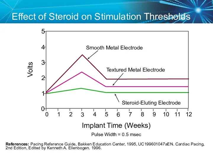
- 57. Steroid Eluting Leads Steroid eluting leads reduce the inflammatory process Exhibit little to no acute stimulation
- 58. Effect of Steroid on Stimulation Thresholds References: Pacing Reference Guide, Bakken Education Center, 1995, UC199601047aEN. Cardiac
- 59. Factors That Can Affect Thresholds Pacemaker circuit (lead) integrity Insulation break Wire fracture The characteristics of
- 60. Myocardial Capture Capture is a function of: Amplitude—the strength of the impulse expressed in volts The
- 61. Comparison 5.0 Volt Amplitude at Different Pulse Widths
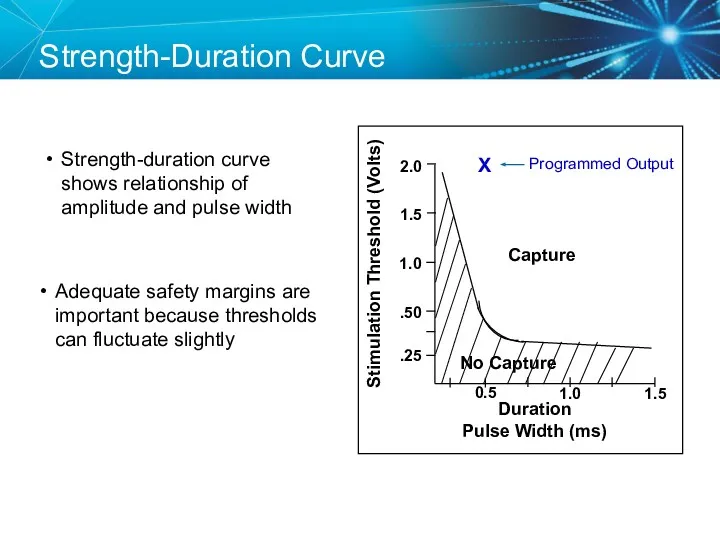
- 62. Duration Pulse Width (ms) Strength-Duration Curve Adequate safety margins are important because thresholds can fluctuate slightly
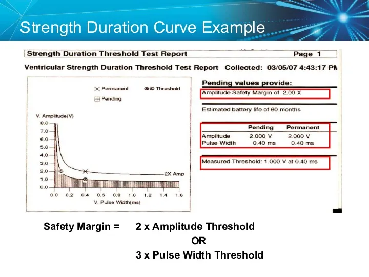
- 63. Strength Duration Curve Example Safety Margin = 2 x Amplitude Threshold OR 3 x Pulse Width
- 64. Programming Outputs Primary goal: Ensure patient safety and appropriate device performance Secondary goal: Extend the service
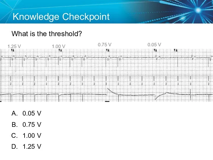
- 65. Knowledge Checkpoint What is the threshold? 1.25 V 0.05 V 0.75 V 1.00 V 0.05 V
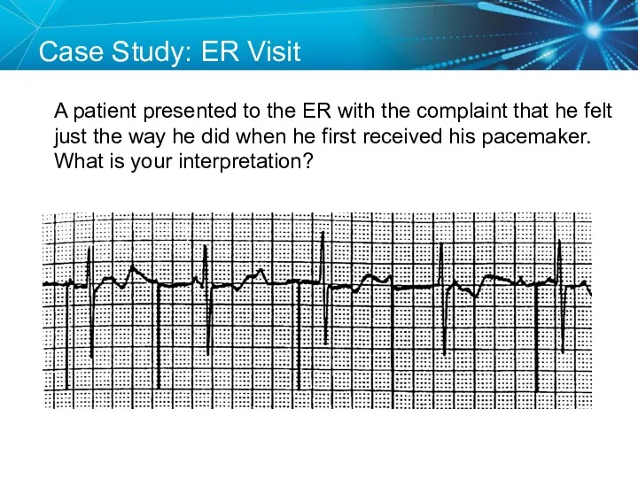
- 66. SETUP: Unknown A patient presented to the ER with the complaint that he felt just the
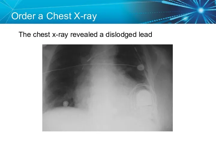
- 67. Order a Chest X-ray The chest x-ray revealed a dislodged lead
- 68. Twiddler’s Syndrome
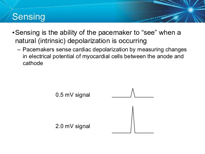
- 69. Sensing Sensing is the ability of the pacemaker to “see” when a natural (intrinsic) depolarization is
- 70. Acceptable Sensing Values (mV)1 Sensing 1Curtis, Anne B. (2010). Fundamentals of Cardiac Pacing. Massachusetts: Jones and
- 71. Sensitivity Amplitude (mV) Time 5.0 2.5 1.25
- 72. Less Sensitive = High Sensitivity Number Amplitude (mV) Time 5.0 2.5 1.25
- 73. More Sensitive = Low Sensitivity Number Amplitude (mV) Time 5.0 2.5 1.25
- 74. Adequate Sensitivity Amplitude (mV) Time 5.0 2.5 1.25
- 75. Sensing Amplifiers/Filters Accurate sensing requires that extraneous signals are filtered out Because whatever a pacemaker senses
- 76. Vectors and Gradients Sense The wave of depolarization produced by normal conduction creates a gradient across
- 77. Changing the Vector Sense A PVC occurs, which is conducted abnormally. Since the vector relative to
- 78. Sensing Accuracy Affected by: Pacemaker circuit (lead) integrity Insulation break Wire fracture The characteristics of the
- 79. Undersensing . . .Overpacing Pacemaker does not “see” the intrinsic beat, and therefore does not respond
- 80. Oversensing …Underpacing An electrical signal other than the intended P or R wave is detected Marker
- 81. Knowledge Checkpoint Which of these pacemakers is more sensitive? OR Programmed Sensitivity 0.5 mV Programmed Sensitivity
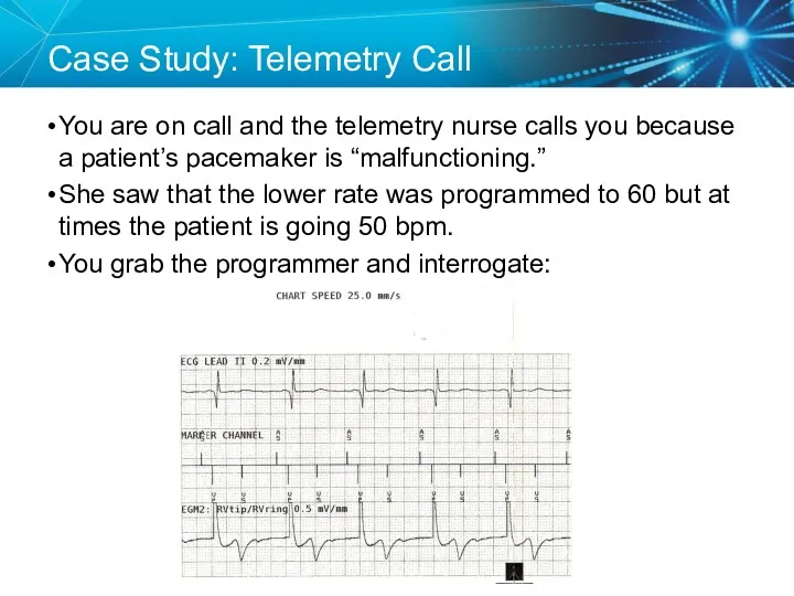
- 82. Case Study: Telemetry Call You are on call and the telemetry nurse calls you because a
- 83. Solution Now that we know what the problem is, How do we fix it? Measure the
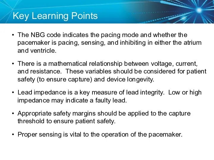
- 84. Key Learning Points The NBG code indicates the pacing mode and whether the pacemaker is pacing,
- 85. Brief Statement: IPGs and ICDs Indications Implantable Pulse Generators (IPGs) are indicated for rate adaptive pacing
- 86. Brief Statement: IPGs and ICDs Contraindications IPGs and CRT IPGs are contraindicated for dual chamber atrial
- 87. Brief Statement: IPGs and ICDs Potential Complications Potential complications include, but are not limited to, rejection
- 88. Brief Statement: Leads Indications Medtronic leads are used as part of a cardiac rhythm disease management
- 89. Brief Statement: Leads Warnings/Precautions People with metal implants such as pacemakers, implantable cardioverter defibrillators (ICDs), and
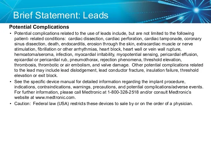
- 90. Brief Statement: Leads Potential Complications Potential complications related to the use of leads include, but are
- 91. Brief Statement: 2090 Programmer Intended Use The Medtronic CareLink programmer system is comprised of prescription devices
- 93. Скачать презентацию
Disclosures
This presentation is provided for general educational purposes only and should
Disclosures
This presentation is provided for general educational purposes only and should
Objectives
Explain the different types of pacemakers and the NBG Code
Identify the
Objectives
Explain the different types of pacemakers and the NBG Code
Identify the

TYPES OF PACEMAKERS
TYPES OF PACEMAKERS
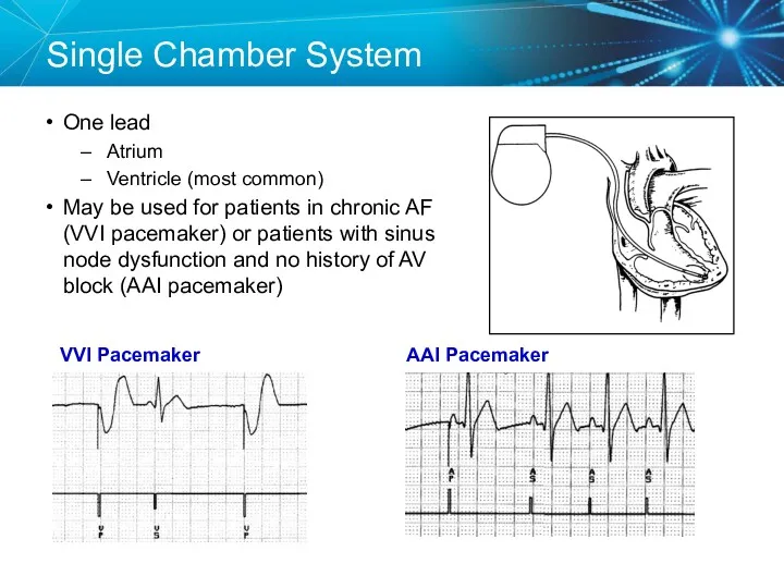
Single Chamber System
One lead
Atrium
Ventricle (most common)
May be used for patients in
Single Chamber System
One lead
Atrium
Ventricle (most common)
May be used for patients in
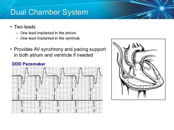
Dual Chamber System
Two leads
One lead implanted in the atrium
One lead
Dual Chamber System
Two leads
One lead implanted in the atrium
One lead
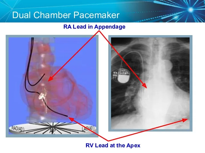
Dual Chamber Pacemaker
RV Lead at the Apex
RA Lead in Appendage
Dual Chamber Pacemaker
RV Lead at the Apex
RA Lead in Appendage
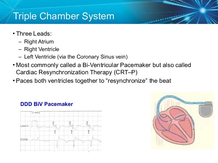
Triple Chamber System
Three Leads:
Right Atrium
Right Ventricle
Left Ventricle (via the Coronary Sinus
Triple Chamber System
Three Leads:
Right Atrium
Right Ventricle
Left Ventricle (via the Coronary Sinus
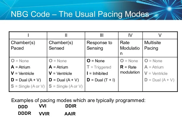
NBG Code – The Usual Pacing Modes
Examples of pacing modes which
NBG Code – The Usual Pacing Modes
Examples of pacing modes which
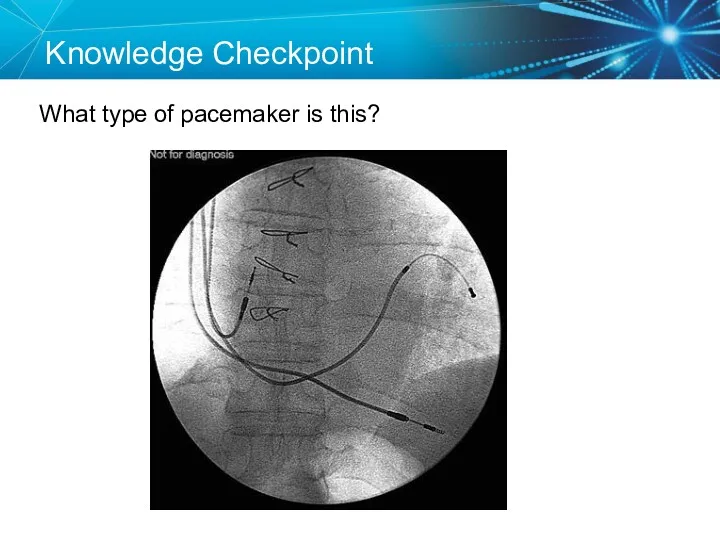
Knowledge Checkpoint
What type of pacemaker is this?
Knowledge Checkpoint
What type of pacemaker is this?
Knowledge Checkpoint
What does VVIR mode mean?
Knowledge Checkpoint
What does VVIR mode mean?
Key Learning Points
There are three types of pacemakers
Important to identify which
Key Learning Points
There are three types of pacemakers
Important to identify which

COMPONENTS OF THE PACEMAKER SYSTEM
COMPONENTS OF THE PACEMAKER SYSTEM

Implantable Pacemaker Circuit
Implantable pulse generator (IPG):
Battery
Circuitry
Connector(s)
Leads or wires
Cathode (negative electrode)
Anode
Implantable Pacemaker Circuit
Implantable pulse generator (IPG):
Battery
Circuitry
Connector(s)
Leads or wires
Cathode (negative electrode)
Anode
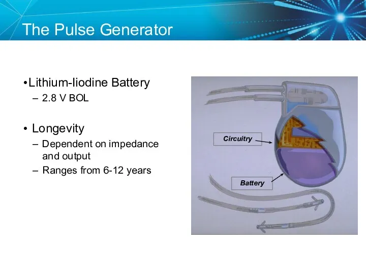
Lithium-Iiodine Battery
2.8 V BOL
Longevity
Dependent on impedance and output
Ranges from 6-12
Lithium-Iiodine Battery
2.8 V BOL
Longevity
Dependent on impedance and output
Ranges from 6-12
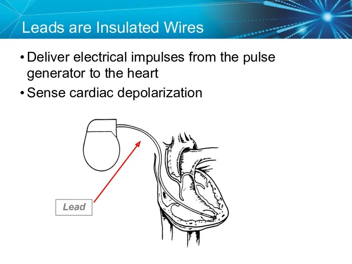
Leads are Insulated Wires
Deliver electrical impulses from the pulse generator to
Leads are Insulated Wires
Deliver electrical impulses from the pulse generator to
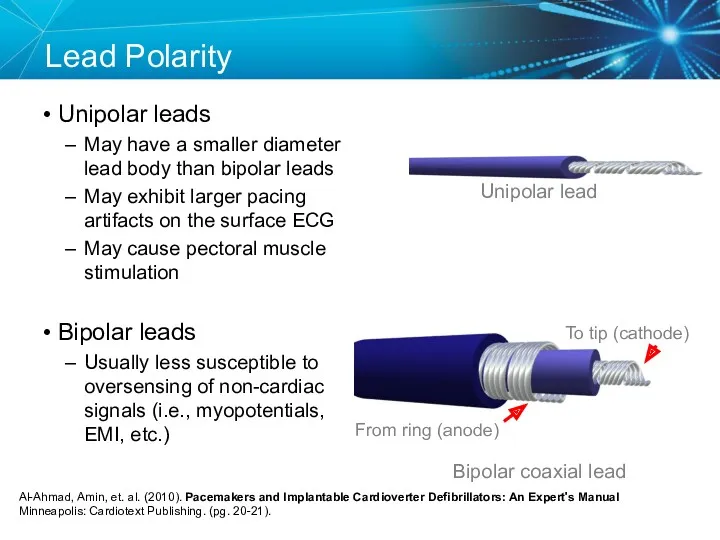
Lead Polarity
Unipolar leads
May have a smaller diameter lead body than
Lead Polarity
Unipolar leads
May have a smaller diameter lead body than
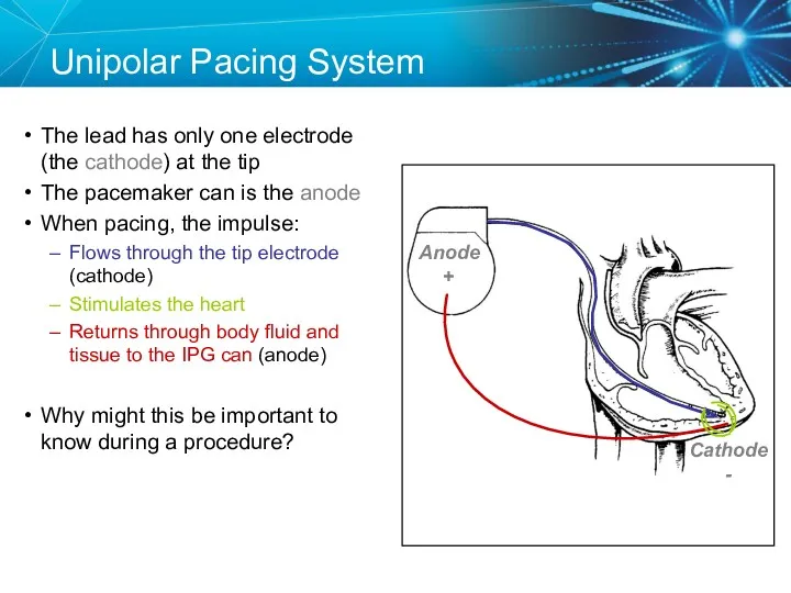
Unipolar Pacing System
The lead has only one electrode (the cathode) at
Unipolar Pacing System
The lead has only one electrode (the cathode) at
Anode
Bipolar Pacing System
The lead has both an anode and cathode
The pacing
Anode
Bipolar Pacing System
The lead has both an anode and cathode
The pacing
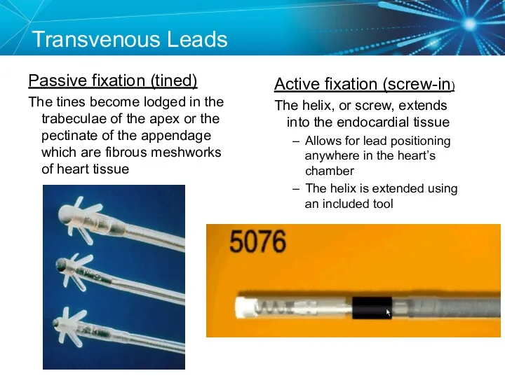
Transvenous Leads
Passive fixation (tined)
The tines become lodged in the trabeculae
Transvenous Leads
Passive fixation (tined)
The tines become lodged in the trabeculae
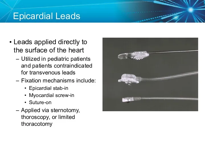
Epicardial Leads
Leads applied directly to the surface of the heart
Utilized in
Epicardial Leads
Leads applied directly to the surface of the heart
Utilized in
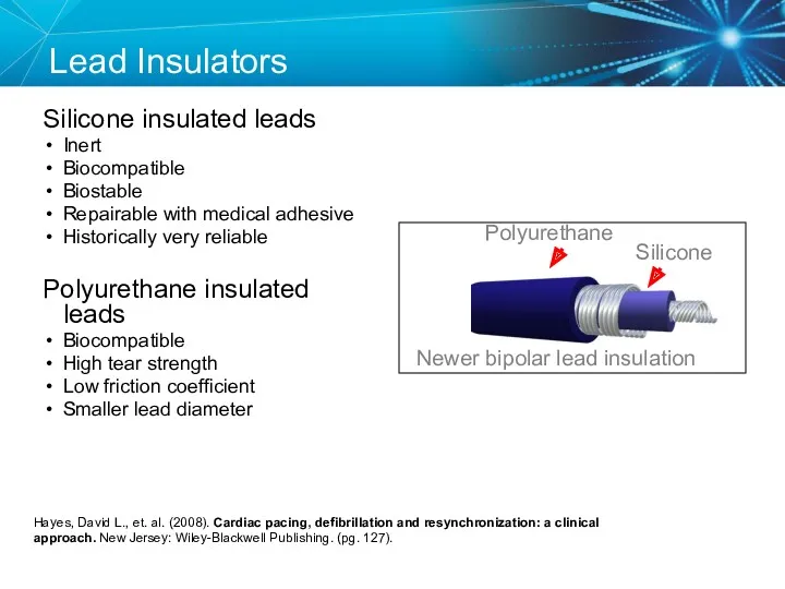
Lead Insulators
Silicone insulated leads
Inert
Biocompatible
Biostable
Repairable with medical adhesive
Historically very reliable
Polyurethane
Lead Insulators
Silicone insulated leads
Inert
Biocompatible
Biostable
Repairable with medical adhesive
Historically very reliable
Polyurethane
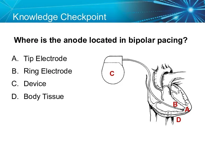
Knowledge Checkpoint
Where is the anode located in bipolar pacing?
C
A
B
D
Tip Electrode
Ring Electrode
Device
Knowledge Checkpoint
Where is the anode located in bipolar pacing?
C
A
B
D
Tip Electrode
Ring Electrode
Device
Key Learning Points
The pacemaker circuit consists of the leads, device, and
Key Learning Points
The pacemaker circuit consists of the leads, device, and

ELECTRICAL CONCEPTS IN PACEMAKERS
ELECTRICAL CONCEPTS IN PACEMAKERS
Voltage
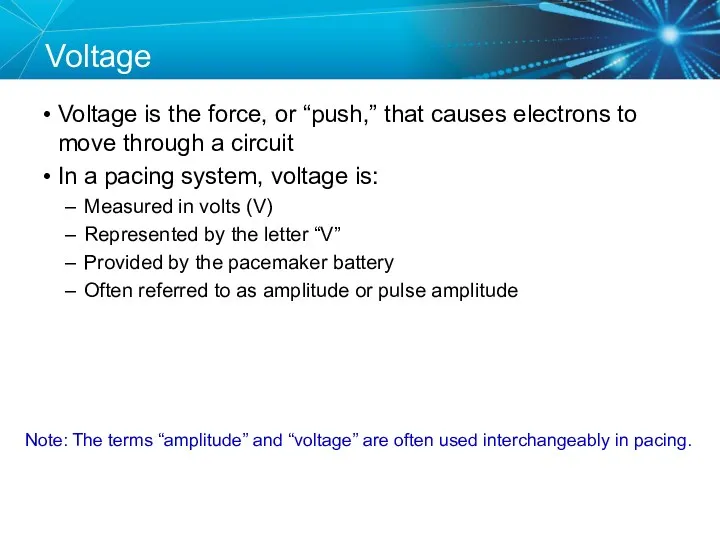
Voltage is the force, or “push,” that causes electrons to move
Voltage
Voltage is the force, or “push,” that causes electrons to move
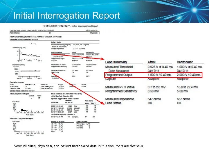
Initial Interrogation Report
Note: All clinic, physician, and patient names and data
Initial Interrogation Report
Note: All clinic, physician, and patient names and data
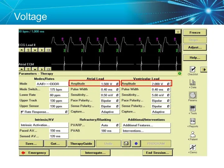
Voltage
Voltage
Current
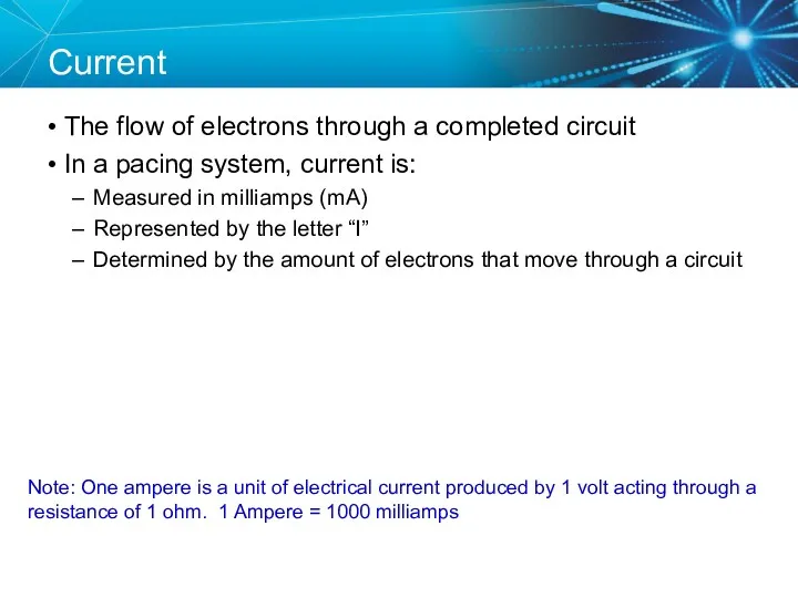
The flow of electrons through a completed circuit
In a pacing system,
Current
The flow of electrons through a completed circuit
In a pacing system,
Current
Current
Impedance
The opposition to current flow
In a pacing system, impedance is:
Measured in
Impedance
The opposition to current flow
In a pacing system, impedance is:
Measured in
Initial Interrogation Report
Note: All clinic, physician, and patient names and data
Initial Interrogation Report
Note: All clinic, physician, and patient names and data
Impedance
Impedance
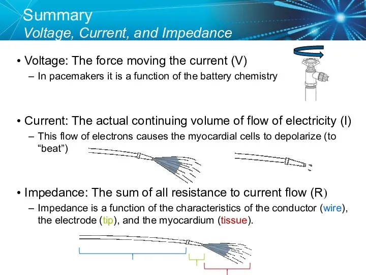
Summary
Voltage, Current, and Impedance
Voltage: The force moving the current (V)
In
Summary
Voltage, Current, and Impedance
Voltage: The force moving the current (V)
In
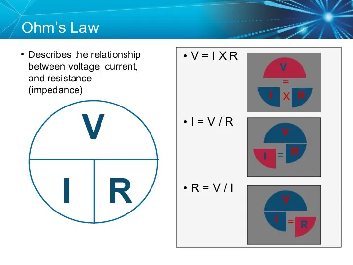
Ohm’s Law
Describes the relationship between voltage, current, and resistance (impedance)
V =
Ohm’s Law
Describes the relationship between voltage, current, and resistance (impedance)
V =
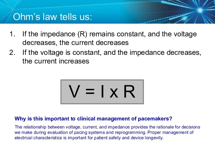
Ohm’s law tells us:
If the impedance (R) remains constant, and the
Ohm’s law tells us:
If the impedance (R) remains constant, and the
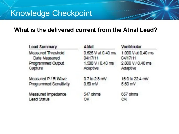
Knowledge Checkpoint
What is the delivered current from the Atrial Lead?
Knowledge Checkpoint
What is the delivered current from the Atrial Lead?
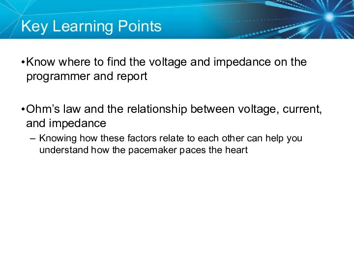
Key Learning Points
Know where to find the voltage and impedance on
Key Learning Points
Know where to find the voltage and impedance on
TESTING THE
PACEMAKER CIRCUIT
TESTING THE
PACEMAKER CIRCUIT
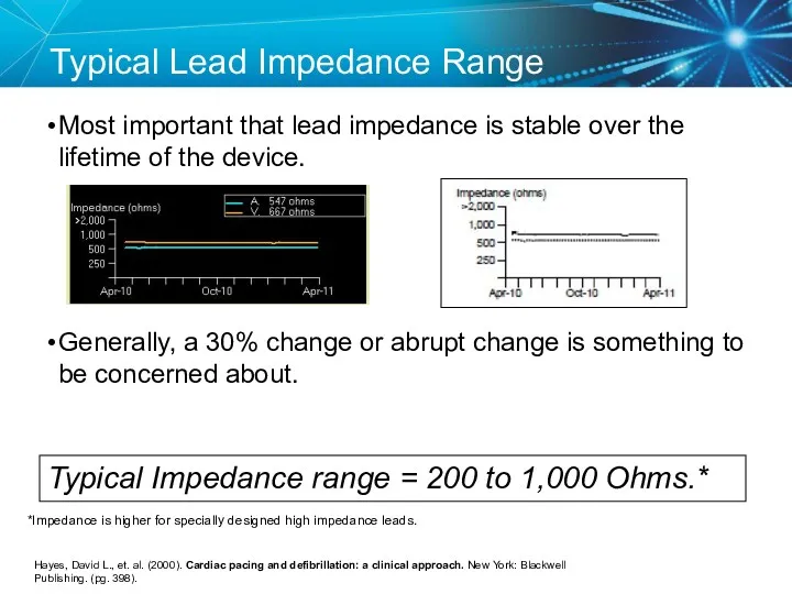
Typical Lead Impedance Range
Most important that lead impedance is stable over
Typical Lead Impedance Range
Most important that lead impedance is stable over
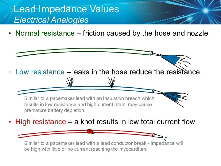
Lead Impedance Values
Electrical Analogies
Normal resistance – friction caused by the
Lead Impedance Values
Electrical Analogies
Normal resistance – friction caused by the
Knowledge Checkpoint
What would you expect to happen if a lead was
Knowledge Checkpoint
What would you expect to happen if a lead was
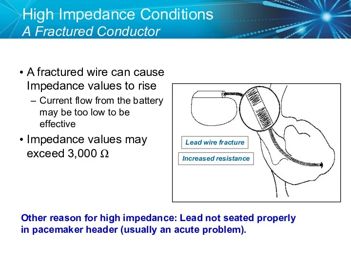
High Impedance Conditions
A Fractured Conductor
A fractured wire can cause Impedance values
High Impedance Conditions
A Fractured Conductor
A fractured wire can cause Impedance values
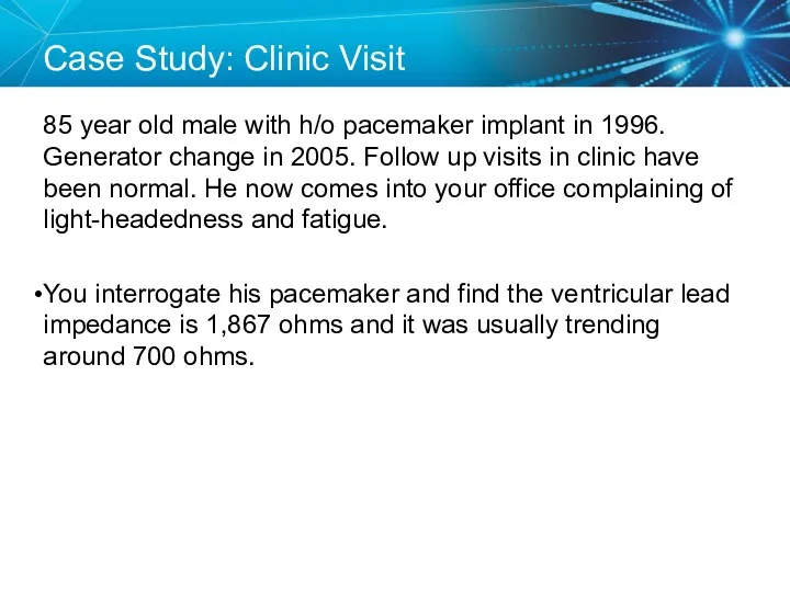
Case Study: Clinic Visit
85 year old male with h/o pacemaker implant
Case Study: Clinic Visit
85 year old male with h/o pacemaker implant
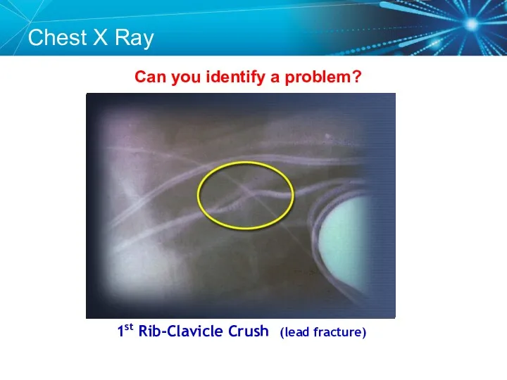
Can you identify a problem?
1st Rib-Clavicle Crush (lead fracture)
Chest X Ray
Can you identify a problem?
1st Rib-Clavicle Crush (lead fracture)
Chest X Ray
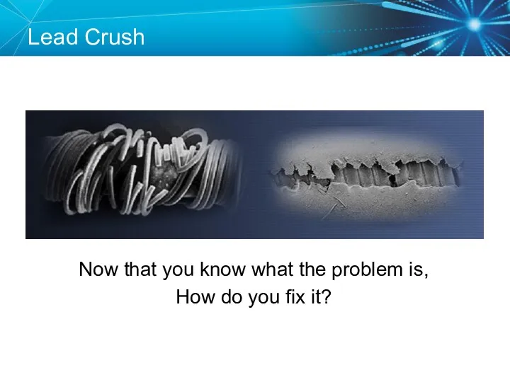
Lead Fracture
Lead Crush
Now that you know what the problem is,
How do
Lead Fracture
Lead Crush
Now that you know what the problem is,
How do
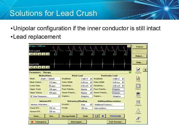
Solutions for Lead Crush
Unipolar configuration if the inner conductor is still
Solutions for Lead Crush
Unipolar configuration if the inner conductor is still
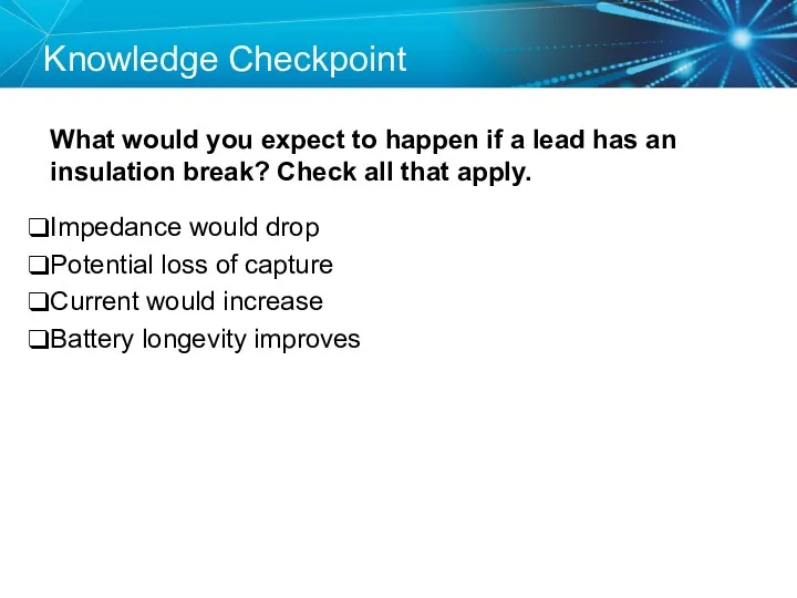
Knowledge Checkpoint
What would you expect to happen if a lead has
Knowledge Checkpoint
What would you expect to happen if a lead has
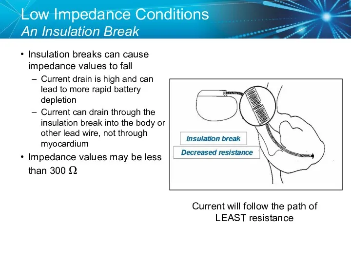
Low Impedance Conditions
An Insulation Break
Insulation breaks can cause impedance values to
Low Impedance Conditions
An Insulation Break
Insulation breaks can cause impedance values to
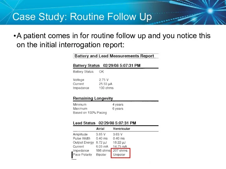
Case Study: Routine Follow Up
A patient comes in for routine follow
Case Study: Routine Follow Up
A patient comes in for routine follow
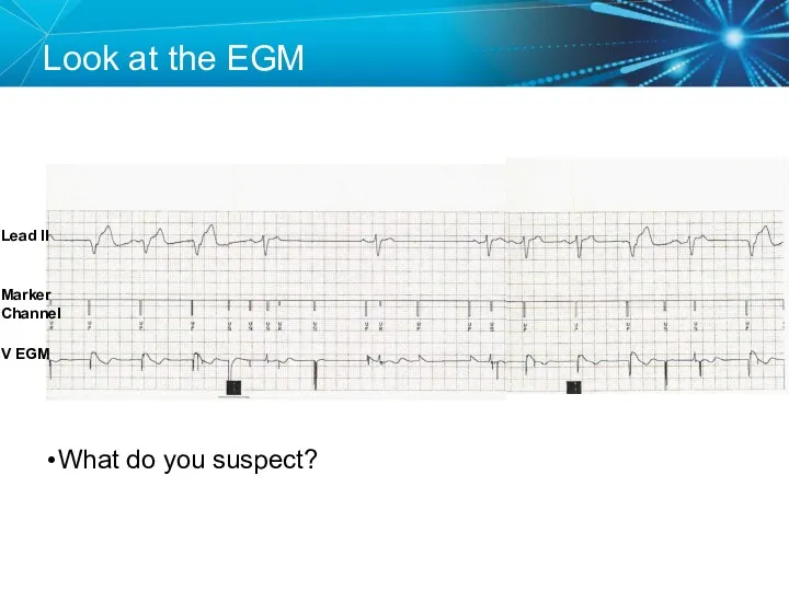
Look at the EGM
What do you suspect?
Lead II
V EGM
Marker Channel
Look at the EGM
What do you suspect?
Lead II
V EGM
Marker Channel
Insulation Break
A low impedance usually means an insulation break
Oversensing can be
Insulation Break
A low impedance usually means an insulation break
Oversensing can be
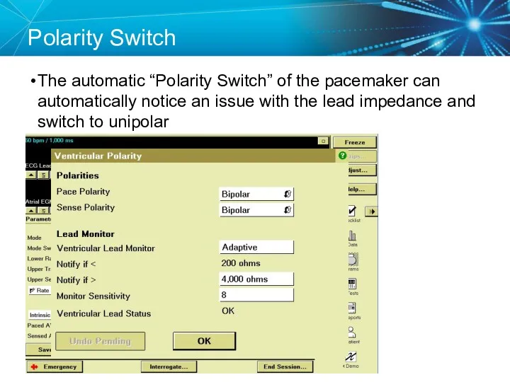
Polarity Switch
The automatic “Polarity Switch” of the pacemaker can automatically notice
Polarity Switch
The automatic “Polarity Switch” of the pacemaker can automatically notice
Replace the Lead
Since the lead is still oversensing and has a
Replace the Lead
Since the lead is still oversensing and has a
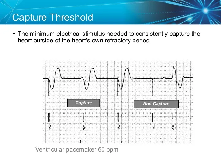
Capture Threshold
The minimum electrical stimulus needed to consistently capture the heart
Capture Threshold
The minimum electrical stimulus needed to consistently capture the heart
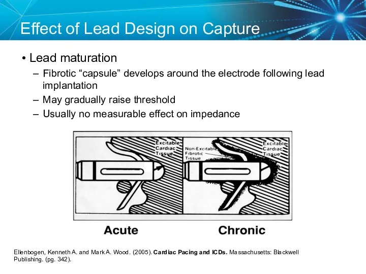
Effect of Lead Design on Capture
Lead maturation
Fibrotic “capsule” develops around
Effect of Lead Design on Capture
Lead maturation
Fibrotic “capsule” develops around
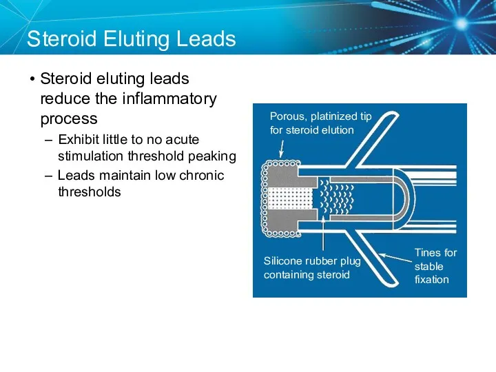
Steroid Eluting Leads
Steroid eluting leads reduce the inflammatory process
Exhibit little
Steroid Eluting Leads
Steroid eluting leads reduce the inflammatory process
Exhibit little
Effect of Steroid on Stimulation Thresholds
References: Pacing Reference Guide, Bakken Education
Effect of Steroid on Stimulation Thresholds
References: Pacing Reference Guide, Bakken Education
Factors That Can Affect Thresholds
Pacemaker circuit (lead) integrity
Insulation break
Wire fracture
The characteristics
Factors That Can Affect Thresholds
Pacemaker circuit (lead) integrity
Insulation break
Wire fracture
The characteristics
Myocardial Capture
Capture is a function of:
Amplitude—the strength of the impulse expressed
Myocardial Capture
Capture is a function of:
Amplitude—the strength of the impulse expressed
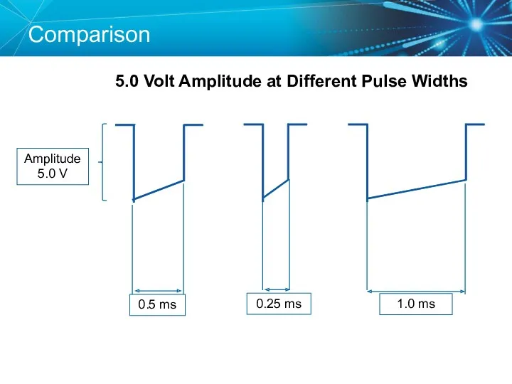
Comparison
5.0 Volt Amplitude at Different Pulse Widths
Comparison
5.0 Volt Amplitude at Different Pulse Widths
Duration
Pulse Width (ms)
Strength-Duration Curve
Adequate safety margins are important because thresholds can
Duration
Pulse Width (ms)
Strength-Duration Curve
Adequate safety margins are important because thresholds can
Strength Duration Curve Example
Safety Margin = 2 x Amplitude Threshold
Strength Duration Curve Example
Safety Margin = 2 x Amplitude Threshold
Programming Outputs
Primary goal: Ensure patient safety and appropriate device performance
Secondary goal:
Programming Outputs
Primary goal: Ensure patient safety and appropriate device performance
Secondary goal:
Knowledge Checkpoint
What is the threshold?
1.25 V
0.05 V
0.75 V
1.00 V
0.05 V
0.75
Knowledge Checkpoint
What is the threshold?
1.25 V
0.05 V
0.75 V
1.00 V
0.05 V
0.75
SETUP: Unknown
A patient presented to the ER with the complaint that
SETUP: Unknown
A patient presented to the ER with the complaint that
Order a Chest X-ray
The chest x-ray revealed a dislodged lead
Order a Chest X-ray
The chest x-ray revealed a dislodged lead
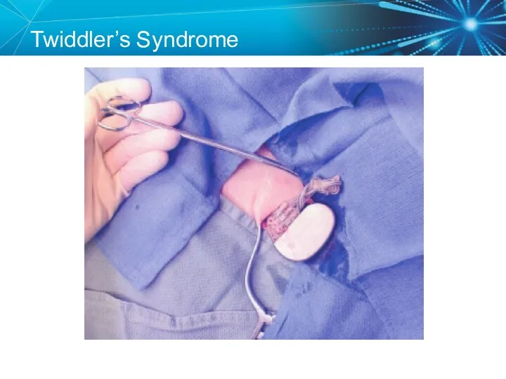
Twiddler’s Syndrome
Twiddler’s Syndrome
Sensing
Sensing is the ability of the pacemaker to “see” when a
Sensing
Sensing is the ability of the pacemaker to “see” when a
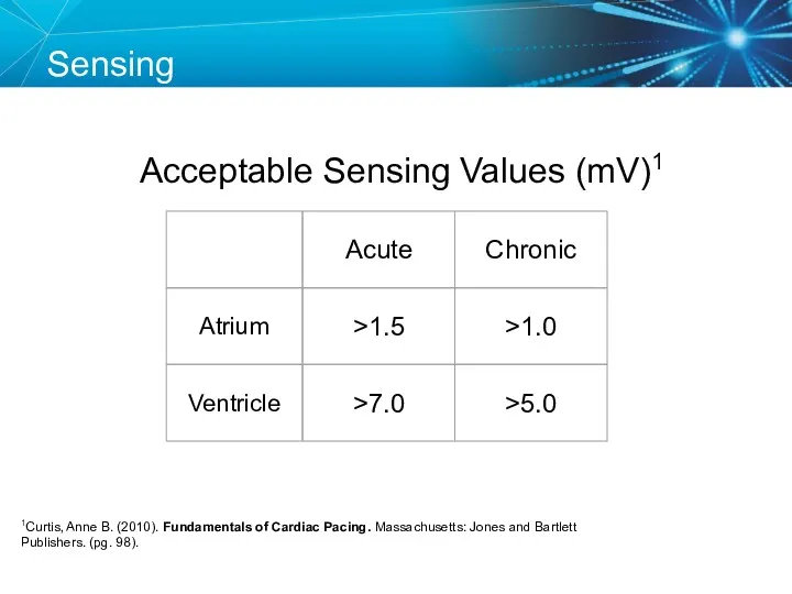
Acceptable Sensing Values (mV)1
Sensing
1Curtis, Anne B. (2010). Fundamentals of Cardiac Pacing.
Acceptable Sensing Values (mV)1
Sensing
1Curtis, Anne B. (2010). Fundamentals of Cardiac Pacing.
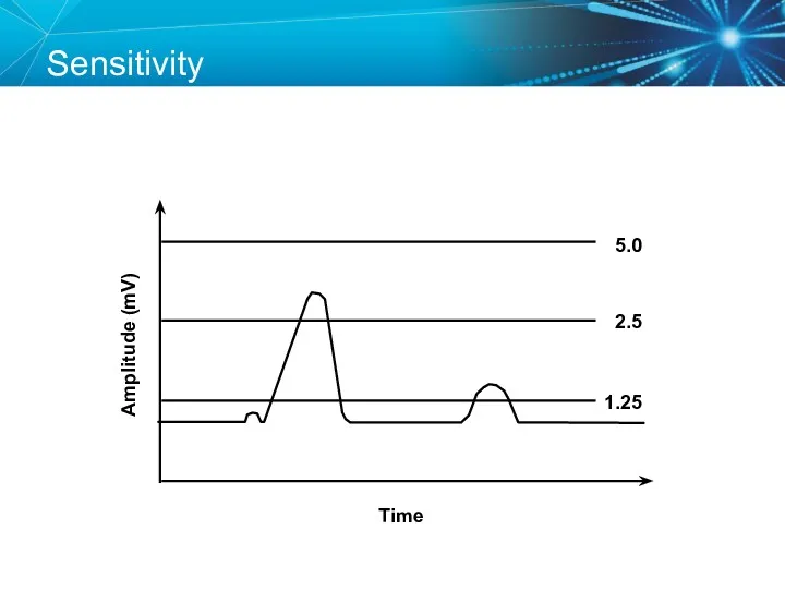
Sensitivity
Amplitude (mV)
Time
5.0
2.5
1.25
Sensitivity
Amplitude (mV)
Time
5.0
2.5
1.25
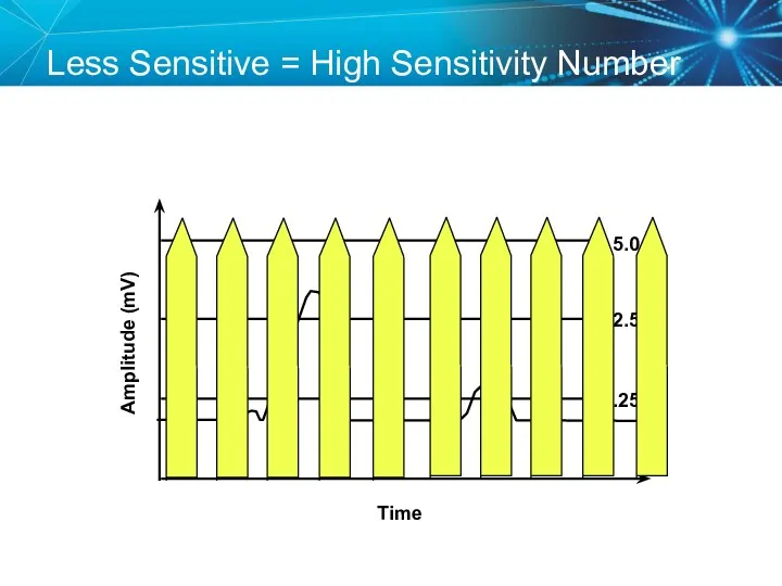
Less Sensitive = High Sensitivity Number
Amplitude (mV)
Time
5.0
2.5
1.25
Less Sensitive = High Sensitivity Number
Amplitude (mV)
Time
5.0
2.5
1.25
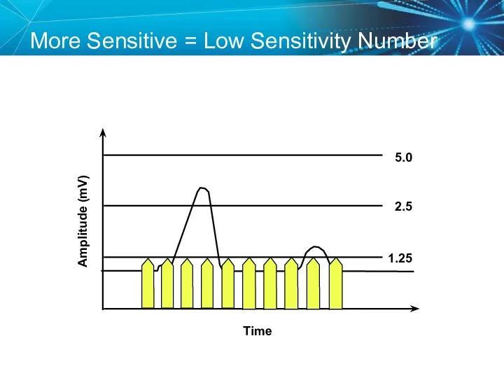
More Sensitive = Low Sensitivity Number
Amplitude (mV)
Time
5.0
2.5
1.25
More Sensitive = Low Sensitivity Number
Amplitude (mV)
Time
5.0
2.5
1.25
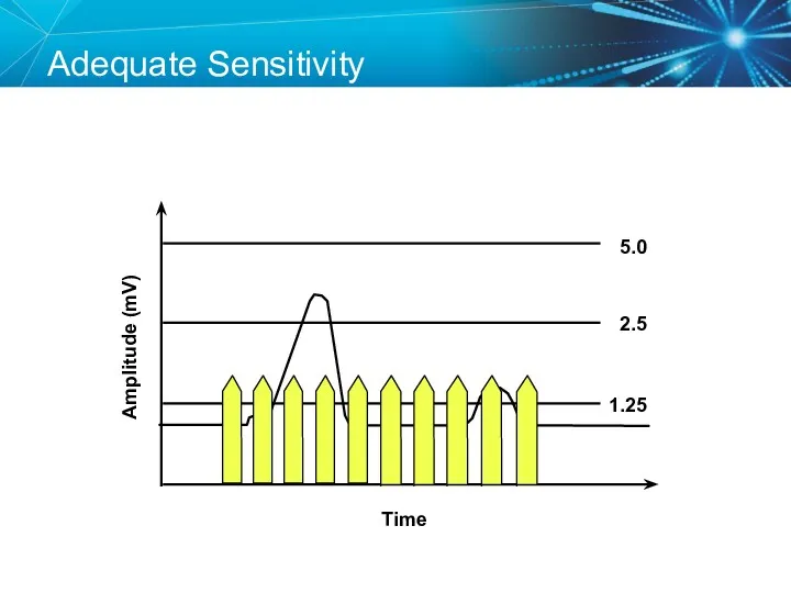
Adequate Sensitivity
Amplitude (mV)
Time
5.0
2.5
1.25
Adequate Sensitivity
Amplitude (mV)
Time
5.0
2.5
1.25
Sensing Amplifiers/Filters
Accurate sensing requires that extraneous signals are filtered out
Because
Sensing Amplifiers/Filters
Accurate sensing requires that extraneous signals are filtered out
Because
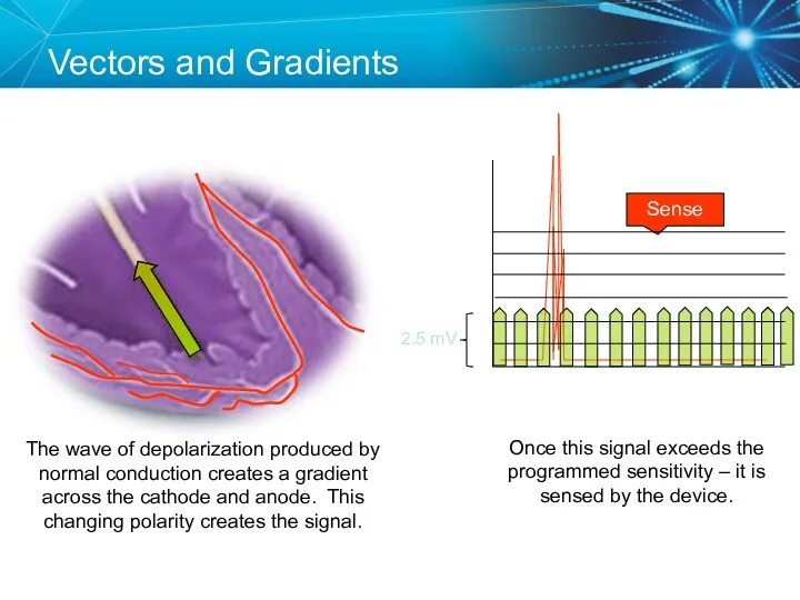
Vectors and Gradients
Sense
The wave of depolarization produced by normal conduction creates
Vectors and Gradients
Sense
The wave of depolarization produced by normal conduction creates
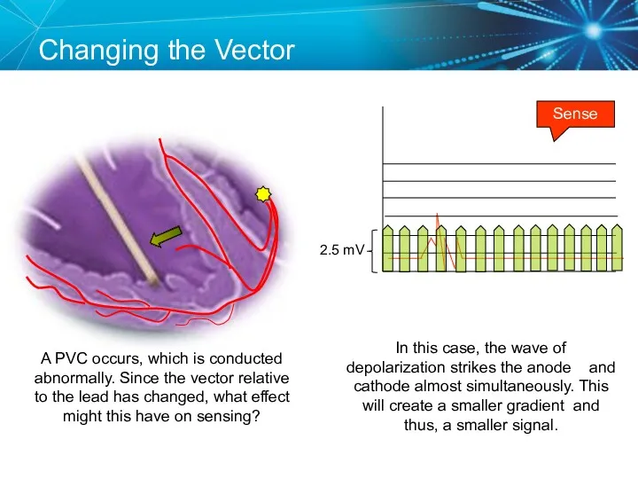
Changing the Vector
Sense
A PVC occurs, which is conducted abnormally. Since the
Changing the Vector
Sense
A PVC occurs, which is conducted abnormally. Since the
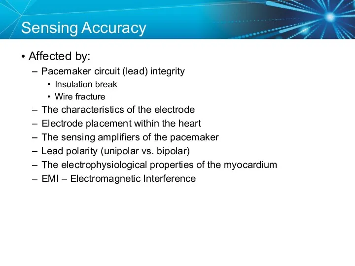
Sensing Accuracy
Affected by:
Pacemaker circuit (lead) integrity
Insulation break
Wire fracture
The characteristics of the
Sensing Accuracy
Affected by:
Pacemaker circuit (lead) integrity
Insulation break
Wire fracture
The characteristics of the
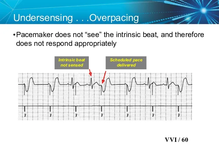
Undersensing . . .Overpacing
Pacemaker does not “see” the intrinsic beat,
Undersensing . . .Overpacing
Pacemaker does not “see” the intrinsic beat,
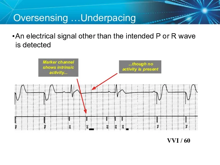
Oversensing …Underpacing
An electrical signal other than the intended P or R
Oversensing …Underpacing
An electrical signal other than the intended P or R
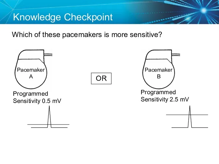
Knowledge Checkpoint
Which of these pacemakers is more sensitive?
OR
Programmed Sensitivity 0.5 mV
Programmed
Knowledge Checkpoint
Which of these pacemakers is more sensitive?
OR
Programmed Sensitivity 0.5 mV
Programmed
Case Study: Telemetry Call
You are on call and the telemetry nurse
Case Study: Telemetry Call
You are on call and the telemetry nurse
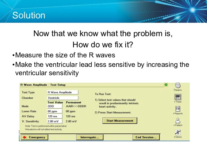
Solution
Now that we know what the problem is,
How do we fix
Solution
Now that we know what the problem is,
How do we fix
Key Learning Points
The NBG code indicates the pacing mode and whether
Key Learning Points
The NBG code indicates the pacing mode and whether
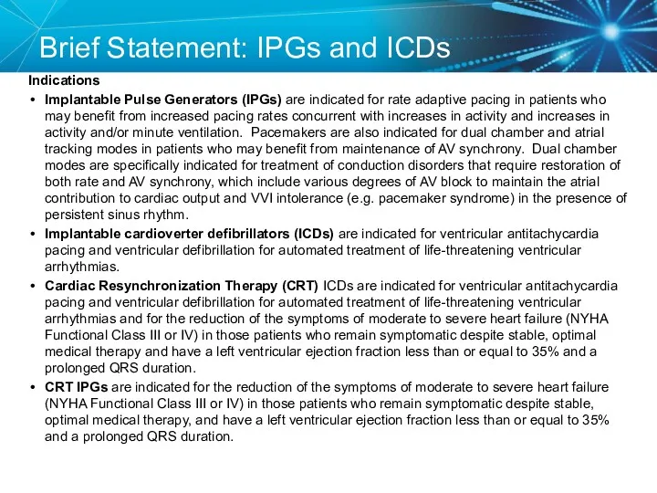
Brief Statement: IPGs and ICDs
Indications
Implantable Pulse Generators (IPGs) are indicated for
Brief Statement: IPGs and ICDs
Indications
Implantable Pulse Generators (IPGs) are indicated for
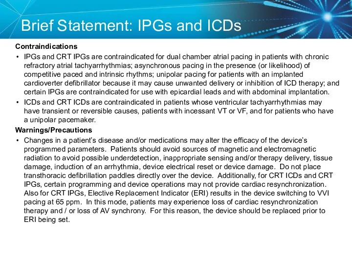
Brief Statement: IPGs and ICDs
Contraindications
IPGs and CRT IPGs are contraindicated
Brief Statement: IPGs and ICDs
Contraindications
IPGs and CRT IPGs are contraindicated
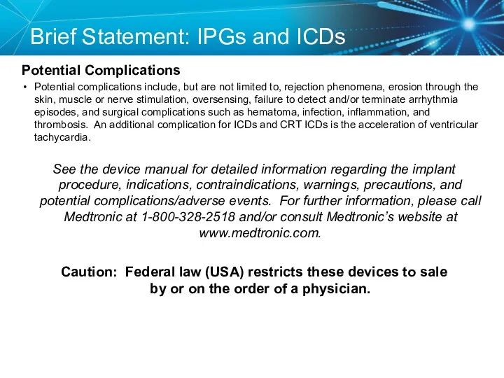
Brief Statement: IPGs and ICDs
Potential Complications
Potential complications include, but are not
Brief Statement: IPGs and ICDs
Potential Complications
Potential complications include, but are not
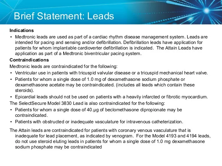
Brief Statement: Leads
Indications
Medtronic leads are used as part of a cardiac
Brief Statement: Leads
Indications
Medtronic leads are used as part of a cardiac
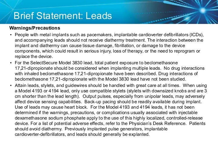
Brief Statement: Leads
Warnings/Precautions
People with metal implants such as pacemakers, implantable cardioverter
Brief Statement: Leads
Warnings/Precautions
People with metal implants such as pacemakers, implantable cardioverter
Brief Statement: Leads
Potential Complications
Potential complications related to the use of leads
Brief Statement: Leads
Potential Complications
Potential complications related to the use of leads
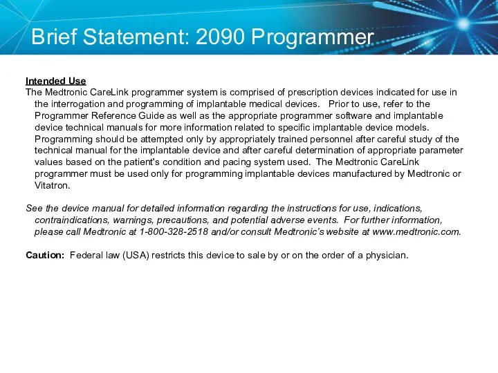
Brief Statement: 2090 Programmer
Intended Use
The Medtronic CareLink programmer system is comprised
Brief Statement: 2090 Programmer
Intended Use
The Medtronic CareLink programmer system is comprised
 Дұрыс тамақтану
 Прогностические шкалы. Классификация, актуальность
 Лечебно –диагностические вмешательства и сестринский уход при заболеваниях глотки
 Лікарські засоби, що діють на кровотворення, систему згортання крові та фібриноліз
 Диагностика цервикальных неоплазий у женщин репродуктивного возраста
 Экстрапирамидные гиперкинезы
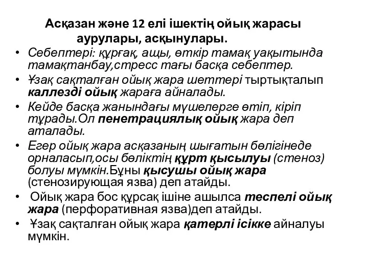 Асқазан және 12 елі ішектің ойық жарасы аурулары, асқынулары
 Факторы риска возникновения парадонта и их устранение
 Фармаконимика. Номенклатура
 Лечения боли у детей
 Предоперационная подготовка гинекологических больных
 Изменения в организме женщины и дискомфортные ощущения во время беременности
 Диагностика кожных высыпаний у детей
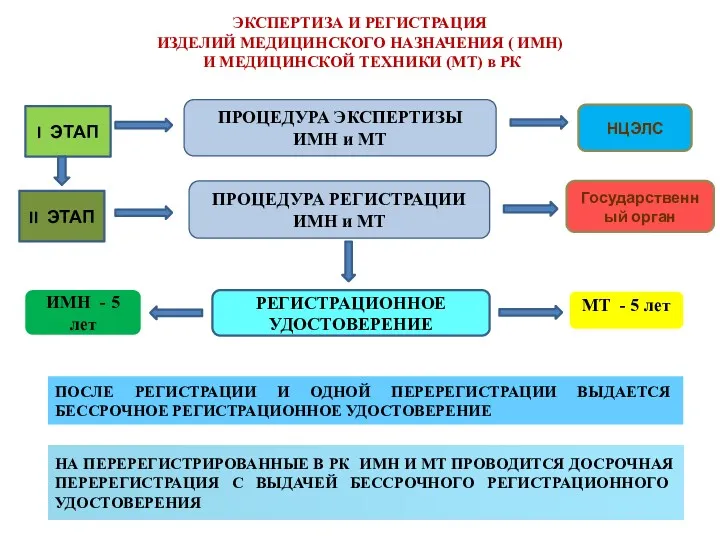 Экспертиза и регистрация изделий медицинского назначения
 История фельдшерского колледжа
 Туберкулездің емі
 Физическая реабилитация при заболеваниях сердечно-сосудистой системы, органов дыхания и пищеварения
 Дерматомиозит
 Неотложная помощь при эпилептическом припадке, эпилептическом статусе
 Алкоголь и его влияние на здоровье человека
 Пиодермии. Определение
 Антибиотики. Определение
 ДариТал клиникасының бизнес-жоспары
 Современная клинико-диагностическая лаборатория. Лабораторные информационные системы
 Доброкачественные и злокачественные опухоли эндокринной системы
 Клиника, диагностика и терапия предменструального синдрома в современных условиях
 Side effects of drugs affecting cardiovascular system
 Диагностика, лечение и профилактика сифилиса: первичный, вторичный, третичный