- 3D-принтер Tronxy P802MHA. Installation guide V.04

Содержание
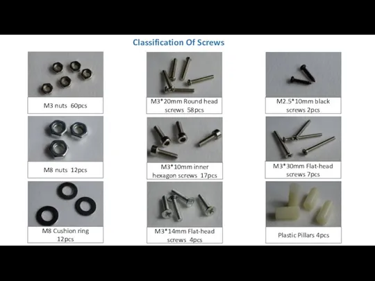
- 2. M3 nuts 60pcs M3*20mm Round head screws 58pcs M2.5*10mm black screws 2pcs M3*10mm inner hexagon screws
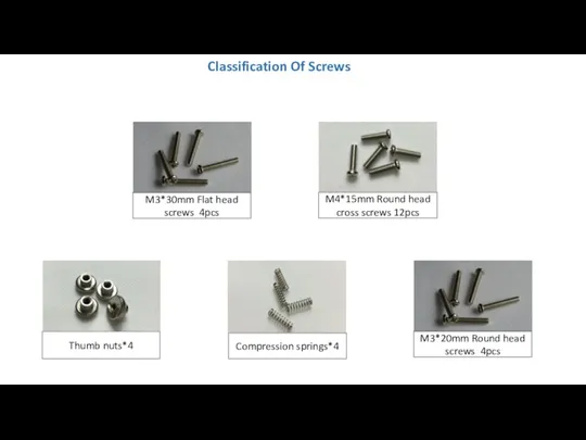
- 3. M4*15mm Round head cross screws 12pcs Compression springs*4 Thumb nuts*4 Classification Of Screws M3*30mm Flat head
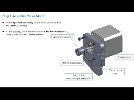
- 4. Step 1 Assemble Y-axis Motor M3*10mm inner hexagon screws*4 Y-axis motor support Y-axis motor M3*2mm jackscrew
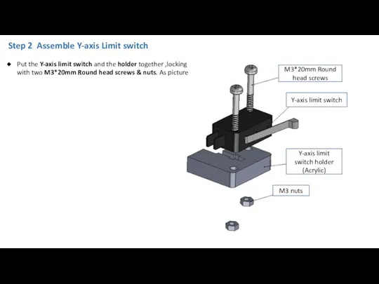
- 5. Step 2 Assemble Y-axis Limit switch Put the Y-axis limit switch and the holder together ,locking
- 6. Step 3 Assemble Base Frame Holder_Back Y-axis motor assembly Sliding rod Restriction*2 M3*20mm screws Y-axis limit
- 7. Step 4 Assemble Base Frame Holder_Front Sliding rod Restriction*2 M3*20mm Round head Screws & nuts Y-axis
- 8. Aluminium plate M3*30mm screws*4 Heat bed M3 nuts Bed frame Bearing*3 Thumb nuts*4 M4*15mm Round head
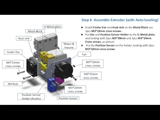
- 9. Position Sensor Step 6 Assemble Extruder (with Auto leveling) U-Metal plate Motor & Hotend Position Sensor
- 10. Step 7 Assemble Z-axis motor coupling M3*20mm Round head screws M3*10mm Inner hexagon screws Z-axis motor
- 11. Z-axis motor assembly Bottom plate M3 nuts M3*20mm Round head screws As the picture, Put the
- 12. Step 9 Assemble Side plate As the picture, Put the two Side plate on the left
- 13. Step 10 Assemble Top plate & Junction Plate Sliding rod restriction Junction Plate Top plate M3*20mm
- 14. Step 11 Install LCD display M3 nuts LCD display assembly M3*25mm Flat head screws Framework (top
- 15. Step 12 Install Power supply Put Power supply on the right of the side plate ,
- 16. Control Board M3 Nuts*8 Plastic Pillars*4 M3*30mm Flat_head Screws *4 Side plate Step 13 Install PCBA
- 17. Step 14 Install Base frame holder_Back Base frame holder_back M3*16mm Round head screws*4 Put the Base
- 18. Step 15 Install Base Frame Holder_Front M8 cushion ring M8*400mm screw arbors Base frame holder_front M8
- 19. Step 16 Instal Platform Assembly Platform assembly M8*380mm sliding rod*2 Sliding rod Restriction The 1pcs bearing
- 20. Acrylic Bed frame Timing belt Belt clip*2 M3*20mm Round head screws &nuts Y-axis belt pulley wheel
- 21. Sliding rod restriction M8*380mm Sliding rod Coupling M8*345mm screw arbor X-axis Pulley mount X-axis Motor mount
- 22. Step 19 Assemble X-axis X-axis motor mount X-axis pulley mount M8*443mm sliding rod Extruder assembly X-axis
- 23. Step 20 Instal X-axis Timing Belt X-axis timing belt Tighten one end of the Timing Belt
- 24. Step 21 Control Board Wiring Diagram The method of connecting wire is as picture !NOTE!: The
- 25. Step 22 AC Power Connector Wiring Diagram Connect Power cable as the picture (Right) Note: There
- 26. Filament spool Filament support frame Fixed Link Steel Pipe M3*20mm Round head screws M3 nuts Steel
- 28. Скачать презентацию
M3 nuts 60pcs
M3*20mm Round head screws 58pcs
M2.5*10mm black screws 2pcs
M3*10mm inner
M3 nuts 60pcs
M3*20mm Round head screws 58pcs
M2.5*10mm black screws 2pcs
M3*10mm inner
M4*15mm Round head cross screws 12pcs
Compression springs*4
Thumb nuts*4
Classification Of Screws
M3*30mm Flat
M4*15mm Round head cross screws 12pcs
Compression springs*4
Thumb nuts*4
Classification Of Screws
M3*30mm Flat
Step 1 Assemble Y-axis Motor
M3*10mm
inner hexagon screws*4
Y-axis motor support
Y-axis motor
M3*2mm
Step 1 Assemble Y-axis Motor
M3*10mm
inner hexagon screws*4
Y-axis motor support
Y-axis motor
M3*2mm
Step 2 Assemble Y-axis Limit switch
Put the Y-axis limit switch and
Step 2 Assemble Y-axis Limit switch
Put the Y-axis limit switch and
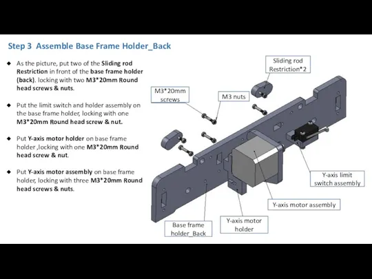
Step 3 Assemble Base Frame Holder_Back
Y-axis motor assembly
Sliding rod Restriction*2
M3*20mm
Step 3 Assemble Base Frame Holder_Back
Y-axis motor assembly
Sliding rod Restriction*2
M3*20mm
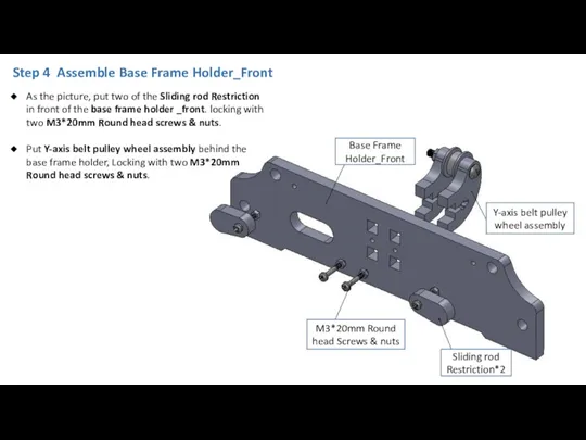
Step 4 Assemble Base Frame Holder_Front
Sliding rod Restriction*2
M3*20mm Round head Screws
Step 4 Assemble Base Frame Holder_Front
Sliding rod Restriction*2
M3*20mm Round head Screws
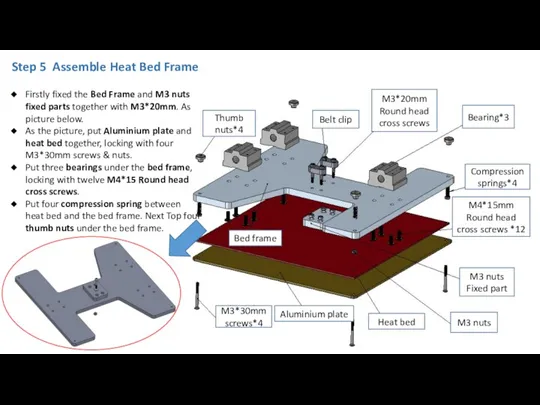
Aluminium plate
M3*30mm screws*4
Heat bed
M3 nuts
Bed frame
Bearing*3
Thumb nuts*4
M4*15mm Round head cross screws
Aluminium plate
M3*30mm screws*4
Heat bed
M3 nuts
Bed frame
Bearing*3
Thumb nuts*4
M4*15mm Round head cross screws
Position Sensor
Step 6 Assemble Extruder (with Auto leveling)
U-Metal plate
Motor & Hotend
Position
Position Sensor
Step 6 Assemble Extruder (with Auto leveling)
U-Metal plate
Motor & Hotend
Position
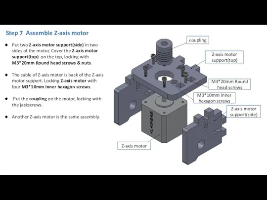
Step 7 Assemble Z-axis motor
coupling
M3*20mm Round head screws
M3*10mm Inner hexagon screws
Z-axis
Step 7 Assemble Z-axis motor
coupling
M3*20mm Round head screws
M3*10mm Inner hexagon screws
Z-axis
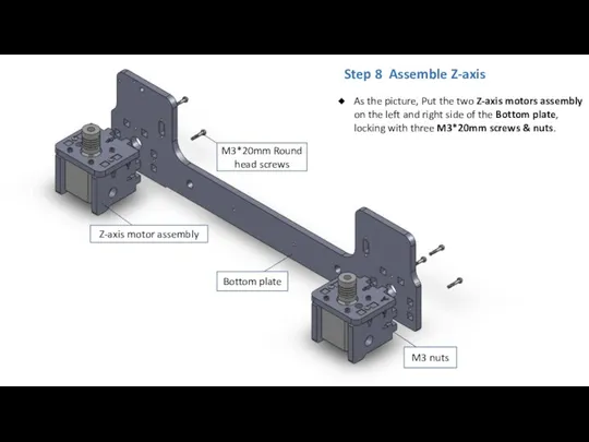
Z-axis motor assembly
Bottom plate
M3 nuts
M3*20mm Round head screws
As the picture, Put
Z-axis motor assembly
Bottom plate
M3 nuts
M3*20mm Round head screws
As the picture, Put
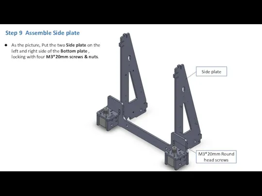
Step 9 Assemble Side plate
As the picture, Put the two Side
Step 9 Assemble Side plate
As the picture, Put the two Side
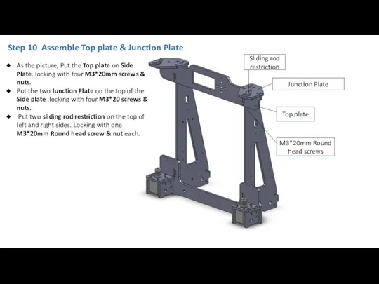
Step 10 Assemble Top plate & Junction Plate
Sliding rod restriction
Junction Plate
Top
Step 10 Assemble Top plate & Junction Plate
Sliding rod restriction
Junction Plate
Top
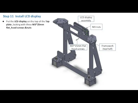
Step 11 Install LCD display
M3 nuts
LCD display assembly
M3*25mm Flat head screws
Framework
Step 11 Install LCD display
M3 nuts
LCD display assembly
M3*25mm Flat head screws
Framework
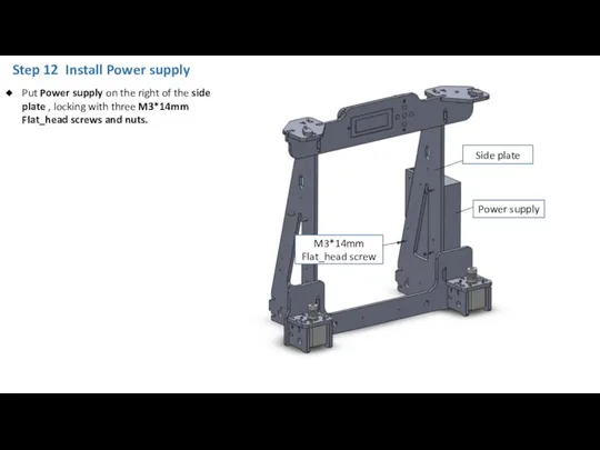
Step 12 Install Power supply
Put Power supply on the right of
Step 12 Install Power supply
Put Power supply on the right of
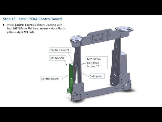
Control Board
M3 Nuts*8
Plastic Pillars*4
M3*30mm Flat_head Screws *4
Side plate
Step 13 Install PCBA
Control Board
M3 Nuts*8
Plastic Pillars*4
M3*30mm Flat_head Screws *4
Side plate
Step 13 Install PCBA

Step 14 Install Base frame holder_Back
Base frame holder_back
M3*16mm Round head screws*4
Put
Step 14 Install Base frame holder_Back
Base frame holder_back
M3*16mm Round head screws*4
Put
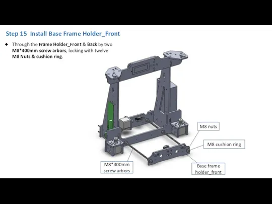
Step 15 Install Base Frame Holder_Front
M8 cushion ring
M8*400mm screw arbors
Base frame
Step 15 Install Base Frame Holder_Front
M8 cushion ring
M8*400mm screw arbors
Base frame
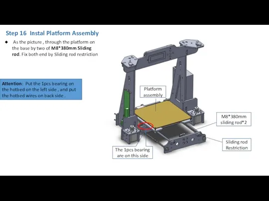
Step 16 Instal Platform Assembly
Platform assembly
M8*380mm sliding rod*2
Sliding rod Restriction
The 1pcs
Step 16 Instal Platform Assembly
Platform assembly
M8*380mm sliding rod*2
Sliding rod Restriction
The 1pcs
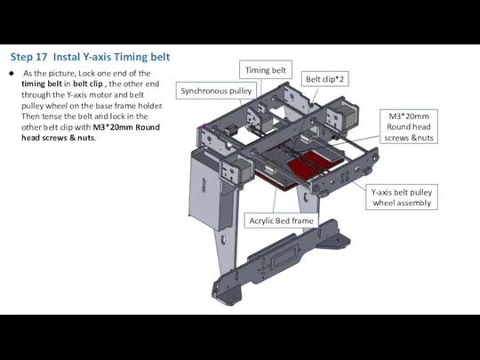
Acrylic Bed frame
Timing belt
Belt clip*2
M3*20mm Round head screws &nuts
Y-axis belt pulley
Acrylic Bed frame
Timing belt
Belt clip*2
M3*20mm Round head screws &nuts
Y-axis belt pulley
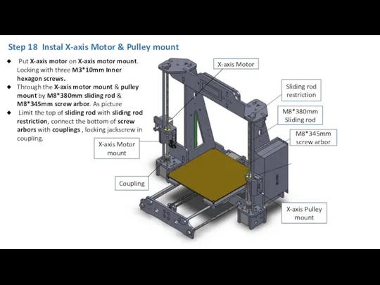
Sliding rod restriction
M8*380mm Sliding rod
Coupling
M8*345mm screw arbor
X-axis Pulley mount
X-axis Motor
Sliding rod restriction
M8*380mm Sliding rod
Coupling
M8*345mm screw arbor
X-axis Pulley mount
X-axis Motor
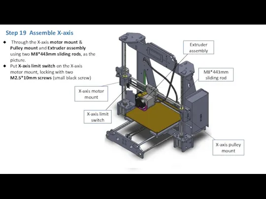
Step 19 Assemble X-axis
X-axis motor mount
X-axis pulley mount
M8*443mm sliding rod
Extruder assembly
X-axis
Step 19 Assemble X-axis
X-axis motor mount
X-axis pulley mount
M8*443mm sliding rod
Extruder assembly
X-axis
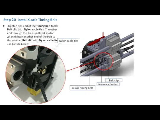
Step 20 Instal X-axis Timing Belt
X-axis timing belt
Tighten one end
Step 20 Instal X-axis Timing Belt
X-axis timing belt
Tighten one end
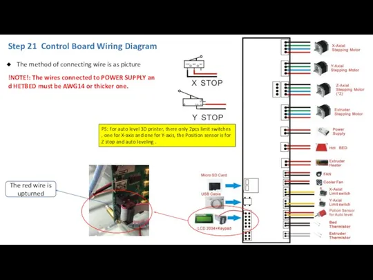
Step 21 Control Board Wiring Diagram
The method of connecting wire is
Step 21 Control Board Wiring Diagram
The method of connecting wire is
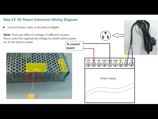
Step 22 AC Power Connector Wiring Diagram
Connect Power cable as
Step 22 AC Power Connector Wiring Diagram
Connect Power cable as
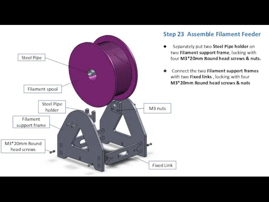
Filament spool
Filament support frame
Fixed Link
Steel Pipe
M3*20mm Round head screws
M3 nuts
Steel Pipe
Filament spool
Filament support frame
Fixed Link
Steel Pipe
M3*20mm Round head screws
M3 nuts
Steel Pipe
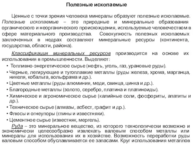 Полезные ископаемые
 Биологиялық мембрананың өткізгіштік механаимі. Иондық каналдар және тасымалдаушылардың құрылысы мен функциясы
 Основы православной культуры
 English-speaking countries. Викторина
 Реализация художественноэстетического направления развития детей дошкольного возраста в аспекте ФГОС ДО по программе Радуга
 Пилигримы в пути
 7 класс: Рельеф С.Америки
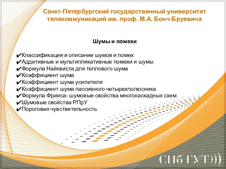 Шумы и помехи
 Бүйрек, несепағар жарақаттары
 Монастыри, основанные Сергием Радонежским
 Кислородные соединения азота
 Презентация Развитие связной речи посредством театрализованной деятельности
 Лучевая диагностика выделительной системы
 Духовная зрелость человека
 Презентация Добрые дела на все времена
 презентация к уроку в 9 классе Тоталитарные режимы 1930-х годов: Италия, Германия, Испания
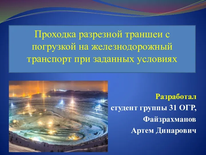 Проходка разрезной траншеи с погрузкой на железнодорожный транспорт при заданных условиях
 Здоровьесберегающие технологии в коррекционной работе с детьми
 Блокада Ленинграда
 Сенсоры. Классификация сенсоров. Миниатюрные электрорадиомеханические и оптоэлектромеханические компоненты
 Приобщение детей к национально-культурным традициям с помощью коллажей и мнемотаблиц
 Tiens-life. Ваше здоровье - в ваших руках!
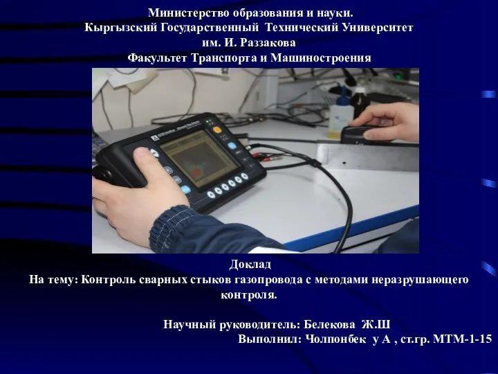 Контроль сварных стыков газопровода с методами неразрушающего контроля
 Объем прямоугольного параллелепипеда и треугольной призмы. Решение задач по готовым чертежам
 Собственный бизнес
 Классный час по теме Конституция РФ
 Презентация Мышление и его роль в профессиональном самоопределении личности
 Письменное деление многозначных чисел на трехзначное число