- A600 Everything for a perfect coffee. Training

Содержание
- 2. A600 Everything for a perfect coffee Intro
- 3. A600 Overview Introduction Technical construction Operation Programming Water flow circuit diagram Accessibility components Commissioning Product adjustment
- 4. A600 Positioning/target groups 150 - 250 cups/day 80 - 150 cups/day 250+ cups/day
- 5. Introduction Dimensions A600
- 6. Introduction Features PERFORMANCE (DOUBLE CUP) / OUTPUT PER HOUR PER DIN 18873-2 Espresso 130 Coffee 100
- 7. Introduction Machine overview Up to two powder dosing units Container capacity each 1 kg Presence/volume monitoring
- 8. Introduction Available version and options MACHINE TYPES: A600 – withou milk A600 MS – Milk system
- 9. Introduction Available version / brewing unit 43E One brewing system for Classic Espresso and perfect milk
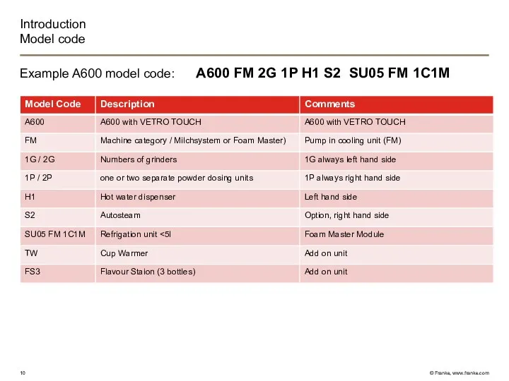
- 10. Introduction Model code Example A600 model code: A600 FM 2G 1P H1 S2 SU05 FM 1C1M
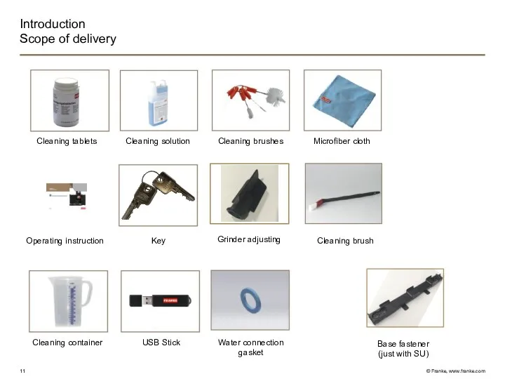
- 11. Introduction Scope of delivery Grinder adjusting Water connection gasket Cleaning brush Key Operating instruction Cleaning tablets
- 12. Introduction Hygiene Short milk tubes between refrigerator and coffee machine Milk pumps in the refrigerator Improved
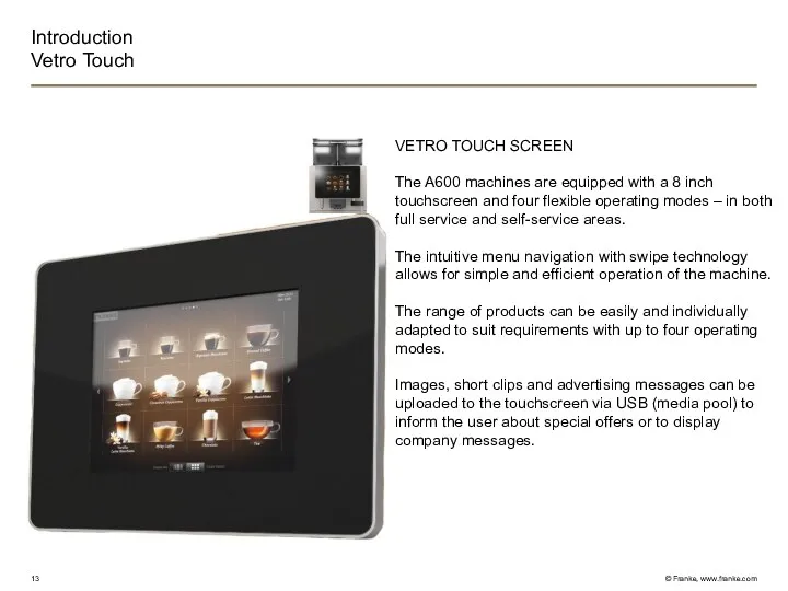
- 13. Introduction Vetro Touch VETRO TOUCH SCREEN The A600 machines are equipped with a 8 inch touchscreen
- 14. Introduction The 4 operating modes SELF-SERVICED «INSPIRE ME» Maximum of six customizable menu cards for the
- 15. Introduction Inspire Me The menu cards can be used to display a pre-selected choice of beverages.
- 16. Introduction Quick Selection Number of beverages: 6, 12 or 20 per page (max. 5 pages) Use
- 17. Introduction Quick select with upselling ideas Characteristics as described under “QUICK SELECT” Selection buttons for beverage
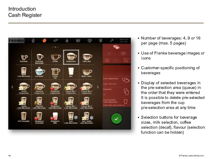
- 18. Introduction Cash Register Number of beverages: 4, 9 or 16 per page (max. 5 pages) Use
- 19. Customers can customize the “QUICK SELECT” mode by uploading their own images to create their own
- 20. Error messages generally appear in the dashboard and light up in different colours. A detailed description
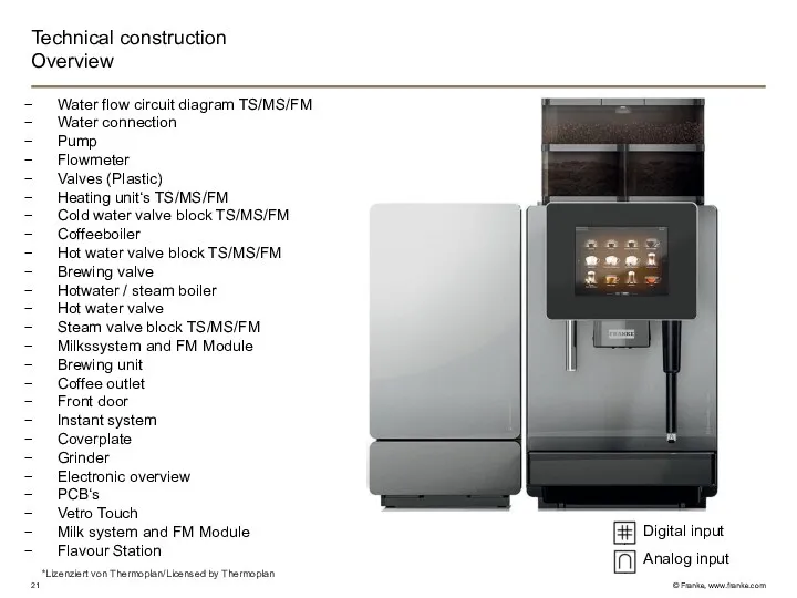
- 21. Technical construction Overview Water flow circuit diagram TS/MS/FM Water connection Pump Flowmeter Valves (Plastic) Heating unit‘s
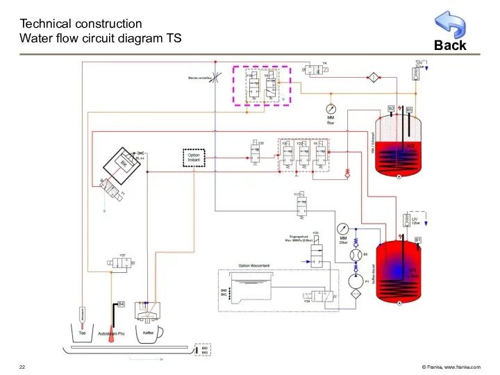
- 22. Technical construction Water flow circuit diagram TS Back
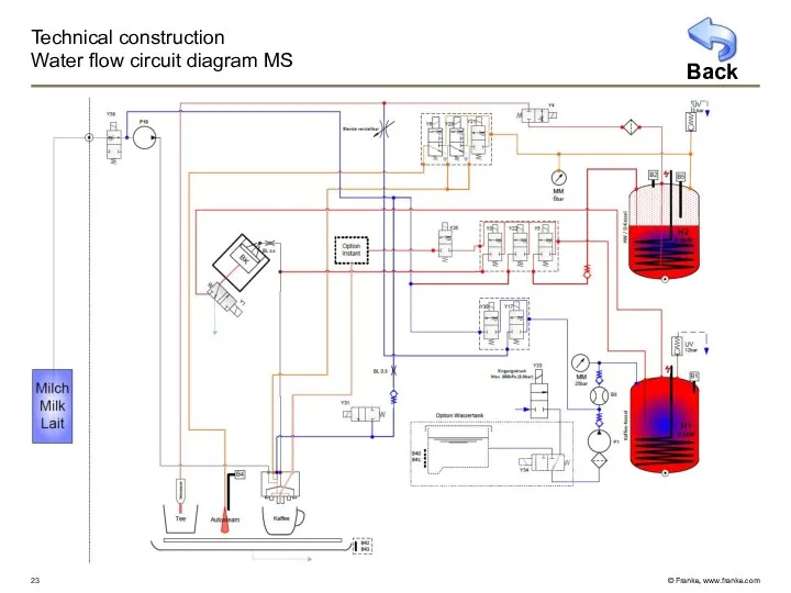
- 23. Technical construction Water flow circuit diagram MS Back
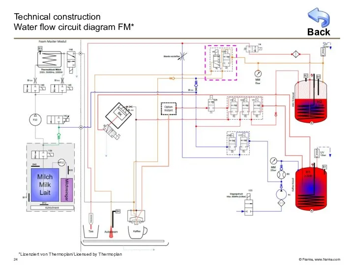
- 24. Technical construction Water flow circuit diagram FM* Back *Lizenziert von Thermoplan/Licensed by Thermoplan
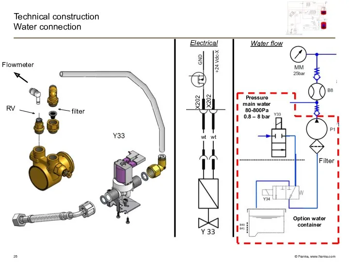
- 25. Technical construction Water connection Y33 Water flow Electrical filter Filter RV RV Flowmeter X202 X202 Pressure
- 26. Technical construction Water gate valve Y34 (only option water tank) Electrical Water flow Filter X202 X202
- 27. Technical construction Pump Bypass Adjustement of water pressure Electrical Water flow X104 X104 Capacitor 7uF Pressure
- 28. Technical construction Flow meter Flow meter: From pump to cold water valve block Coffee boiler supply
- 29. Technical construction 2/2- way plastic valve 1) 2) 3) 4) 6) 5) 7) 9) 10) a)
- 30. Technical construction 3/2 way plastic valve 1) 2) 3) 4) 6) 5) 7) 8) 9) Coil
- 31. Technical construction Heating unit TS 6) 9) 10) 2) 7) 8) 3) 1) 4) 5) Y1
- 32. Technical construction Heating unit MS 6) 9) 10) 2) 7) 8) 3) 1) 4) 5) Y1
- 33. Technical construction Heating unit FM* Heating unit Pressure gauge Cold water valve block Y30, Y17 Brewing
- 34. Technical construction Cold water valve block (TS) Y17: Function: cold water by-pass valve Cable: green Remark:
- 35. Technical construction Cold water valve block (TS) GND +24V DCs X202 X202 gn gn Y17 Water
- 36. Technical construction Cold water valve block (MS) Y30: Function: cold water rinsing line Cable: white Remark:
- 37. Technical construction Cold water valve block (MS) GND +24V DCs X202 X202 gn gn Water flow
- 38. Technical construction Cold water valve block (FM*) Y17 2) 1) 3) 4) Y30 5) Back *Lizenziert
- 39. Technical construction Cold water valve block (FM) Waterflow GND +24V DCs X202 X202 gn gn Electrical
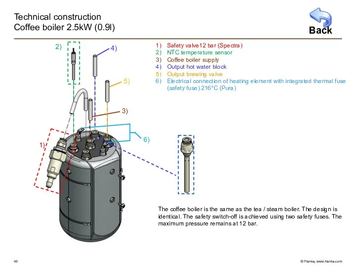
- 40. Technical construction Coffee boiler 2.5kW (0.9l) Safety valve12 bar (Spectra) NTC temperature sensor Coffee boiler supply
- 41. Technical construction Coffee boiler 2.5kW (0.9l) Electrical N rd H1 bl K2 b a Thermal fuse
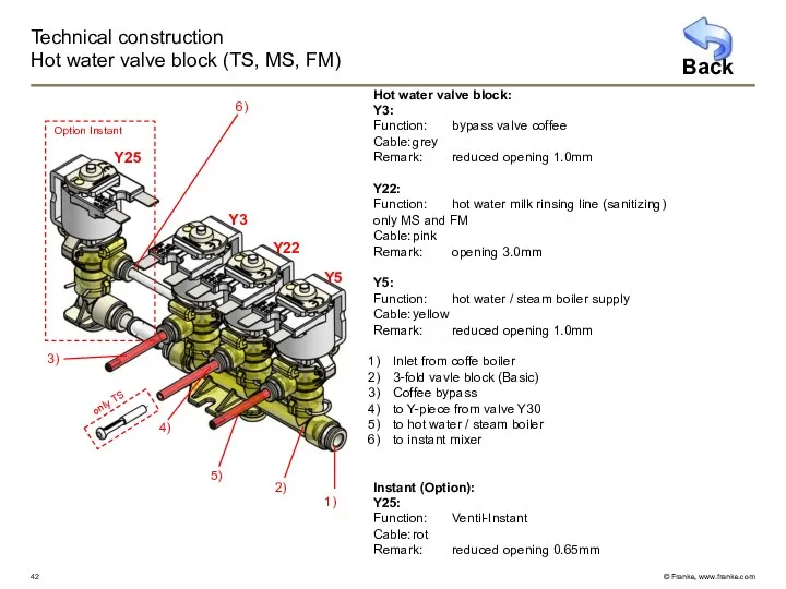
- 42. Technical construction Hot water valve block (TS, MS, FM) Hot water valve block: Y3: Function: bypass
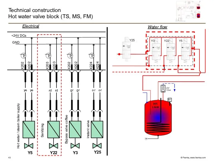
- 43. Technical construction Hot water valve block (TS, MS, FM) GND +24V DCs X202 X202 X203 X203
- 44. Technical construction Brewing valve Y1 (TS, MS, FM) GND +24V DCs Electrical X202 X202 bn bn
- 45. Technical construction Hot water / steam boiler, 2.5kW (0.9l) NTC temperature sensor Level probe l=84 mm
- 46. Technical construction Hot water / steam boiler, 2.5kW (0.9l) STB Water flow Electrical N gr H2
- 47. Technische Konstruktion Hot water valve (TS, MS, FM) 1) 2) 3) Y4: Function: Hot water /
- 48. Technical construction Steam valve block (TS, MS, FM) GND +24V DCs X202 X202 bl bl Y4
- 49. Technical construction Steam valve block TS Y6: Fuction: Autosteam (3/2 way valve) Cable: brown Remark: Opening
- 50. Technical construction Steam valve block TS GND +24V DCs X203 X203 X203 X203 br br bl
- 51. Technical construction Steam valve block MS Y6: Function: Autosteam (3/2-way valve) Cable: brown Remark: opening 3.0mm
- 52. Technical construction Steam valve block MS GND +24V DCs X203 X203 X203 X203 br br vi
- 53. Technical construction Steam valve block FM Y6: Function: Autosteam (3/2-way valve) Cable: brown Remark: opening 3.0mm
- 54. Technical construction Steam valve block FM GND +24V DCs X203 X203 X203 X203 br br vi
- 55. Technical construction Brewing unit – drive frame DC-Motor with encoder Bar Reed sensor Locking lever for
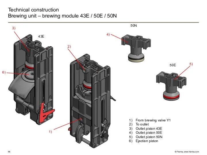
- 56. Technical construction Brewing unit – brewing module 43E / 50E / 50N 43E 50N 50E From
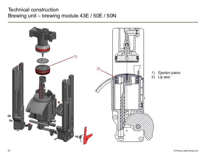
- 57. Technical construction Brewing unit – brewing module 43E / 50E / 50N Ejection piston Lip seal
- 58. Lower limit/Re-calibration point (current rise, position “0”) Cleaning and dismounting position Powder chute position and grinding
- 59. Technical construction Brewing unit Coffee Water flow Electrical Encoder DC-Motor rd bl ye gr br bu
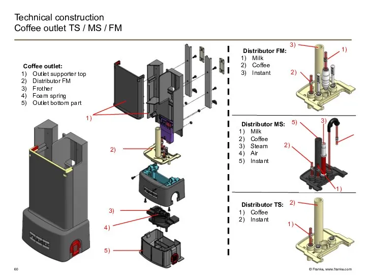
- 60. Technical construction Coffee outlet TS / MS / FM Distributor FM: Milk Coffee Instant Coffee outlet:
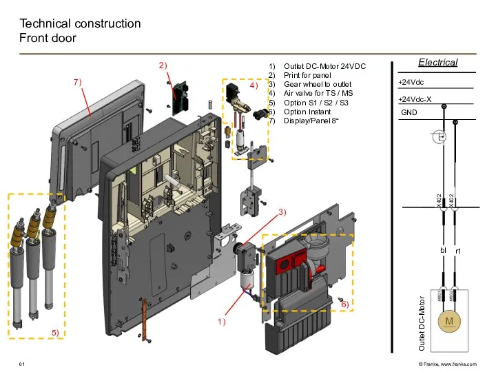
- 61. Technical construction Front door Electrical Outlet Motor GND +24Vdc-X +24Vdc Outlet DC-Motor bl rt Outlet DC-Motor
- 62. Technichal construction Air valve (front door) Air valve Y31 – for machine type MS Air valve
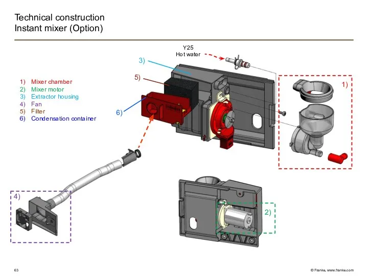
- 63. Technical construction Instant mixer (Option) 1) 2) 3) Mixer chamber Mixer motor Extractor housing Fan Filter
- 64. Pulverdosierer rechts Technical construction Coverplate / Instant Coverplate Blind cover Grinder insert with bean monitoring Cover
- 65. Technical construction Coverplate / layout of containers 1 2 3 4
- 66. Technical construction Instant Electrical GND +24Vdc-X +24Vdc Instant fan Instant valve Mixer motor Instant right hand
- 67. Technical construction Grinder (Pura) Grinder right Mühle links 1) 2) 3) 4) 6) 5) Specification of
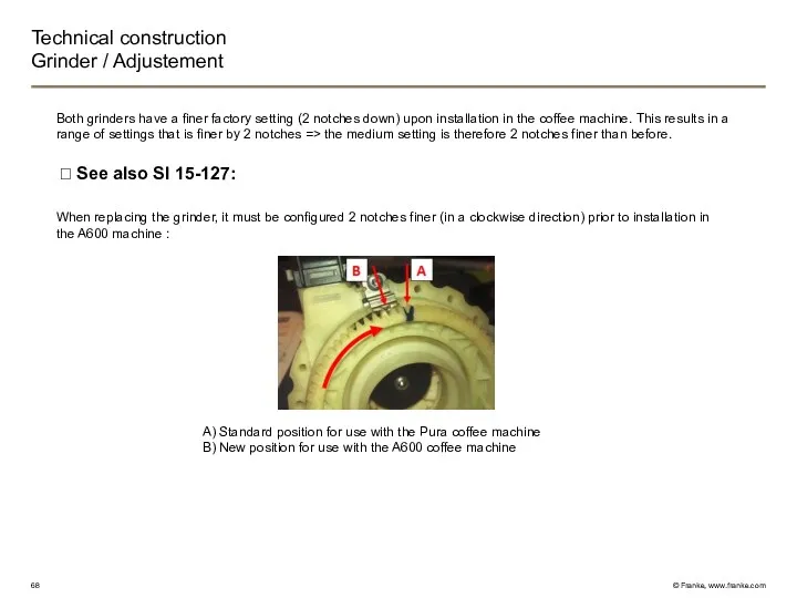
- 68. Technical construction Grinder / Adjustement A) Standard position for use with the Pura coffee machine B)
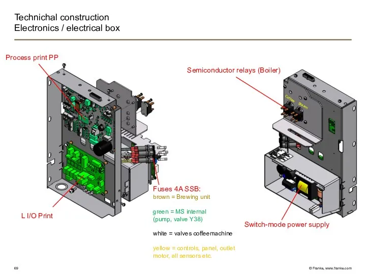
- 69. Technichal construction Electronics / electrical box Switch-mode power supply L I/O Print Semiconductor relays (Boiler) Process
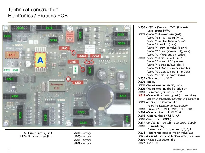
- 70. Technical construction Electronics / Process PCB X200 - X202 - X203 - X205 - X206 -
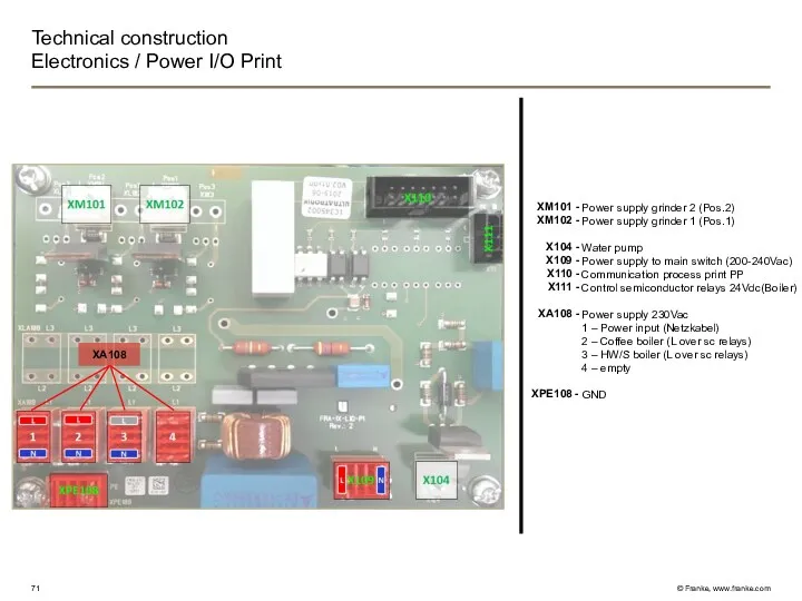
- 71. Technical construction Electronics / Power I/O Print XM101 - XM102 - X104 - X109 - X110
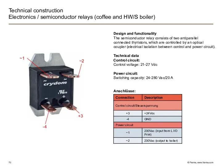
- 72. Technical construction Electronics / semiconductor relays (coffee and HW/S boiler) Design and functionality The semiconductor relay
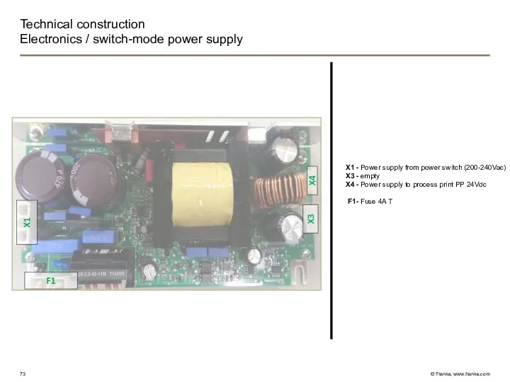
- 73. Technical construction Electronics / switch-mode power supply X1 - X3 - X4 - F1- Power supply
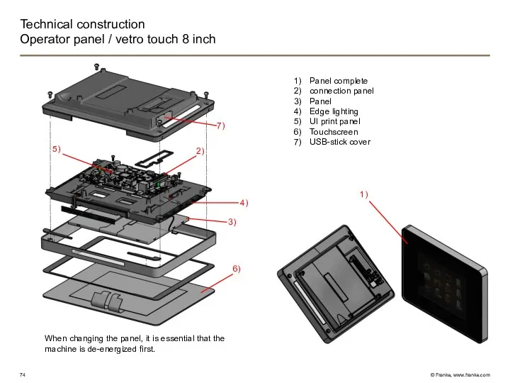
- 74. Technical construction Operator panel / vetro touch 8 inch Panel complete connection panel Panel Edge lighting
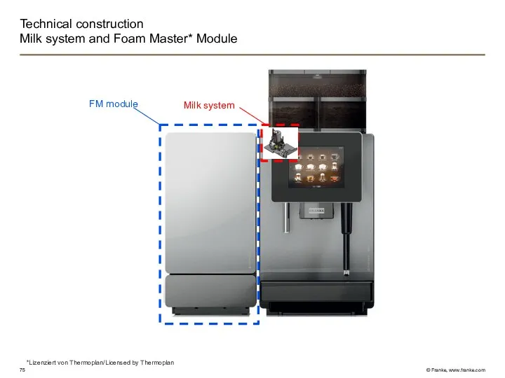
- 75. Technical construction Milk system and Foam Master* Module *Lizenziert von Thermoplan/Licensed by Thermoplan FM module Milk
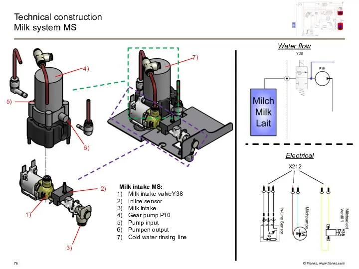
- 76. Technical construction Milk system MS Milk intake MS: Milk intake valveY38 Inline sensor Milk intake Gear
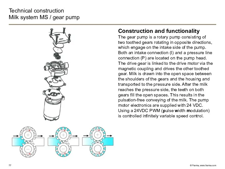
- 77. Technical construction Milk system MS / gear pump Construction and functionality The gear pump is a
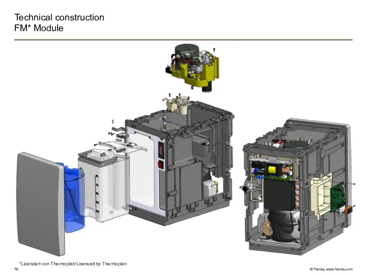
- 78. Technical construction FM* Module *Lizenziert von Thermoplan/Licensed by Thermoplan
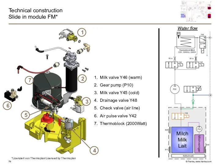
- 79. Technical construction Slide in module FM* Water flow Milk valve Y46 (warm) Gear pump (P10) Milk
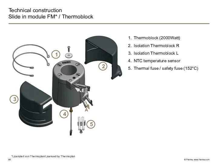
- 80. Technical construction Slide in module FM* / Thermoblock Thermoblock (2000Watt) Isolation Thermoblock R Isolation Thermoblock L
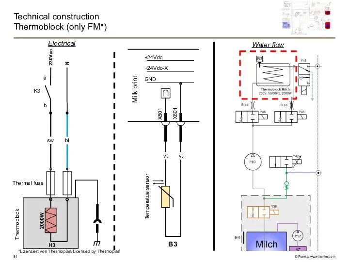
- 81. Technical construction Thermoblock (only FM*) Water flow Electrical 230Vac N sw H3 bl K3 b a
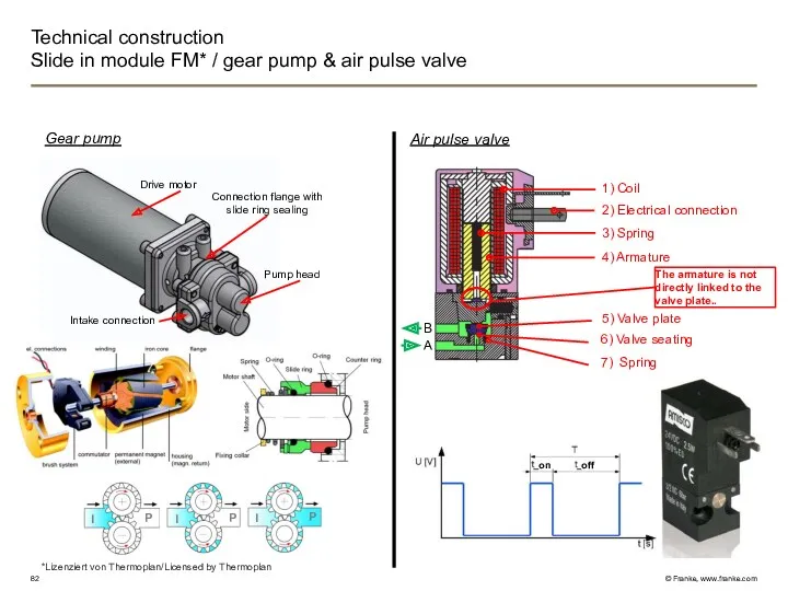
- 82. Technical construction Slide in module FM* / gear pump & air pulse valve 1) Coil 2)
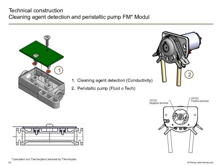
- 83. Technical construction Cleaning agent detection and peristaltic pump FM* Modul Cleaning agent detection (Conductivity) Peristaltic pump
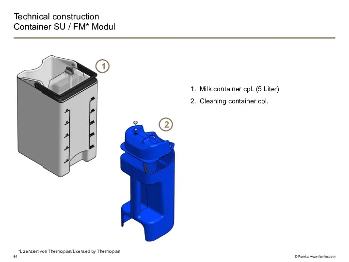
- 84. Technical construction Container SU / FM* Modul Milk container cpl. (5 Liter) Cleaning container cpl. 1
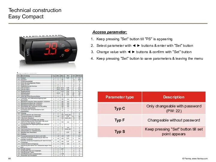
- 85. Technical construction Easy Compact Access parameter: Keep pressing "Set" button till "PS" is appearing Select parameter
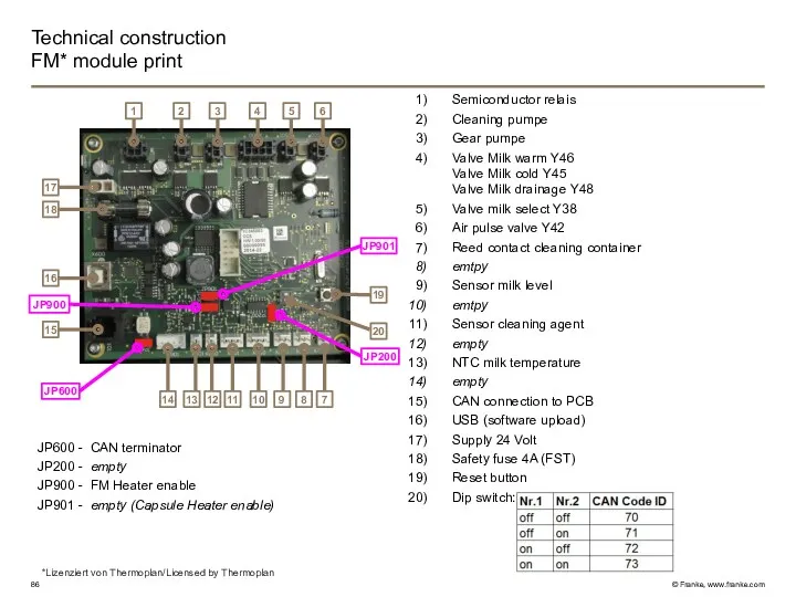
- 86. Technical construction FM* module print Semiconductor relais Cleaning pumpe Gear pumpe Valve Milk warm Y46 Valve
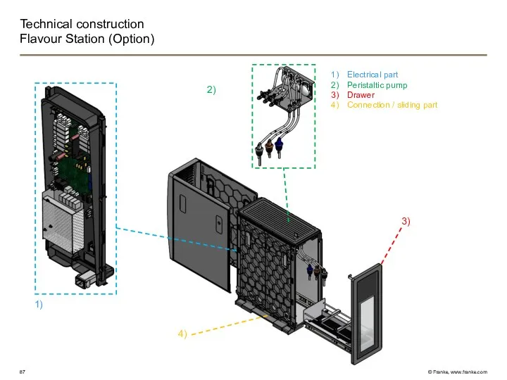
- 87. Technical construction Flavour Station (Option) Electrical part Peristaltic pump Drawer Connection / sliding part 2) 1)
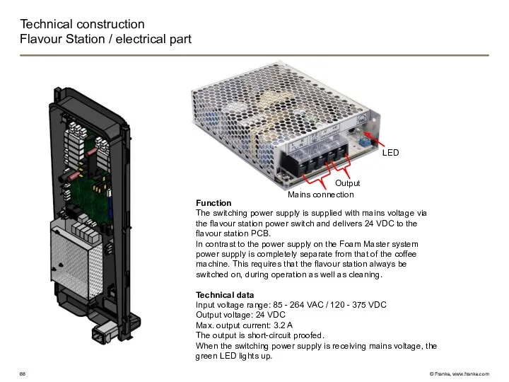
- 88. Technical construction Flavour Station / electrical part Function The switching power supply is supplied with mains
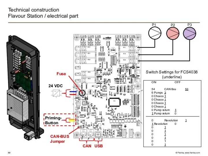
- 89. Technical construction Flavour Station / electrical part P1 P3 P2 24 VDC USB CAN Priming- Button
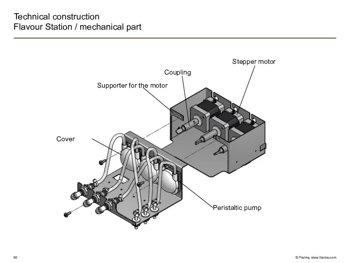
- 90. Technical construction Flavour Station / mechanical part Stepper motor Coupling Supporter for the motor Peristaltic pump
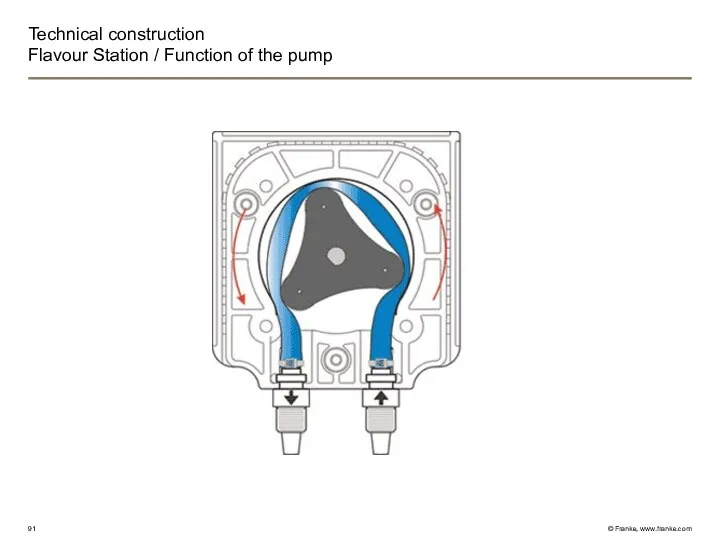
- 91. Technical construction Flavour Station / Function of the pump
- 92. Operating Switch over to the Maintenance level by tipping on the Franke logo in the upper
- 93. Operating Operator panel construction FCS4043
- 94. Operating Input methods
- 95. Programming Service Menu
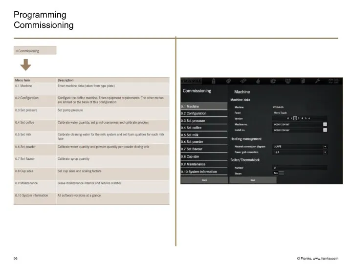
- 96. Programming Commissioning FCS4026
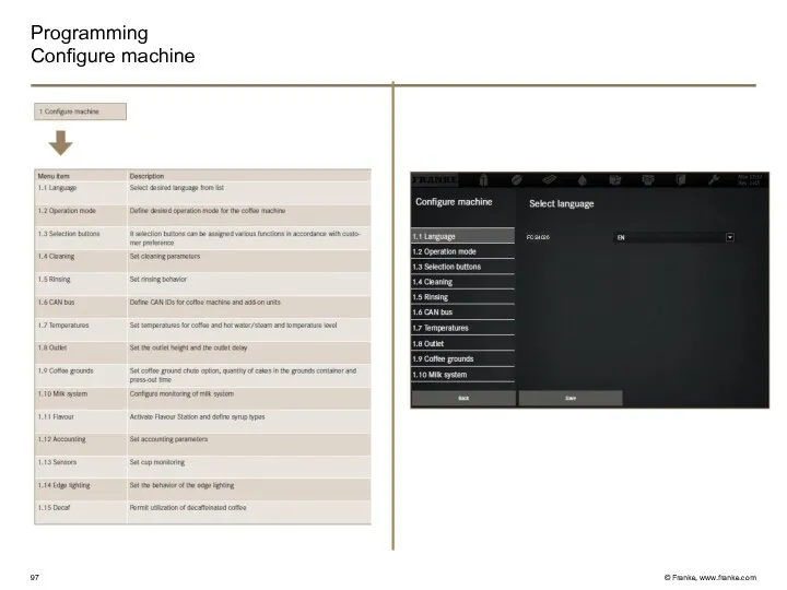
- 97. Programming Configure machine FCS4026
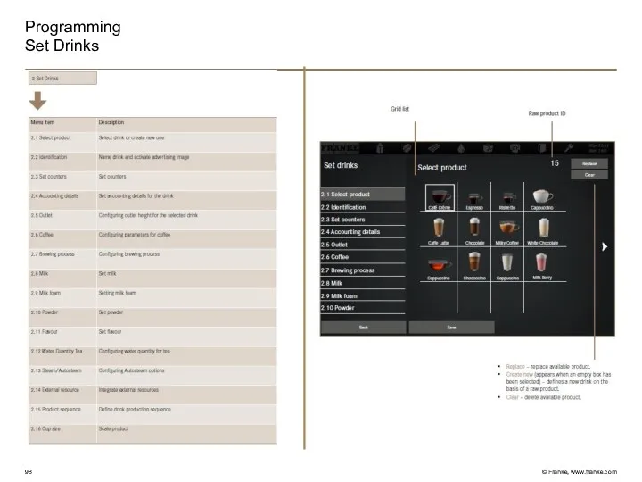
- 98. Programming Set Drinks
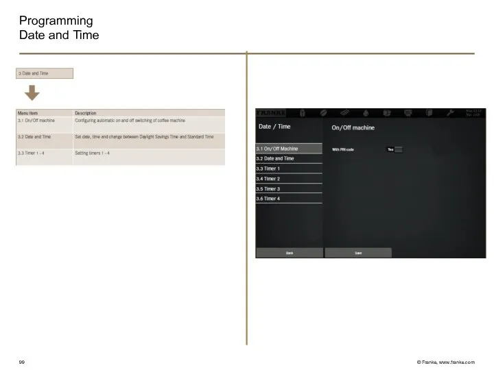
- 99. Programming Date and Time
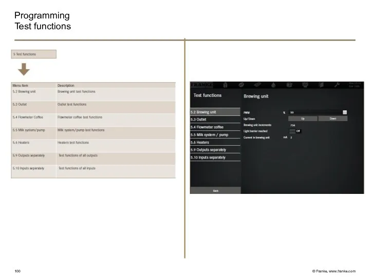
- 100. Programming Test functions
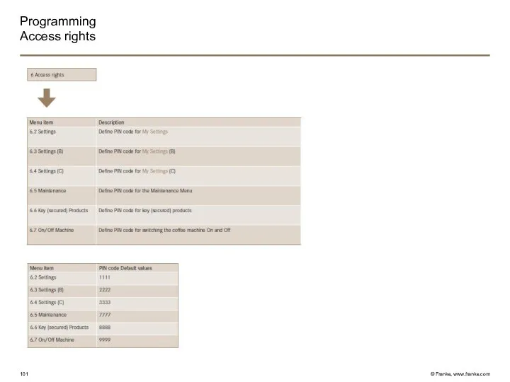
- 101. Programming Access rights
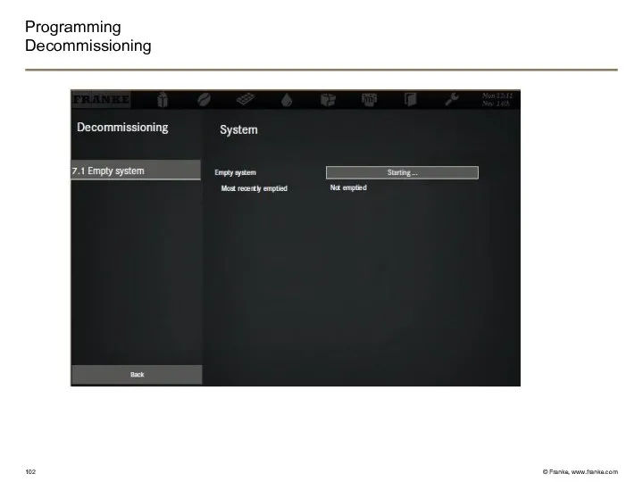
- 102. Programming Decommissioning
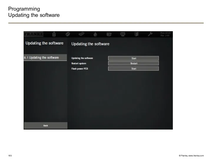
- 103. Programming Updating the software
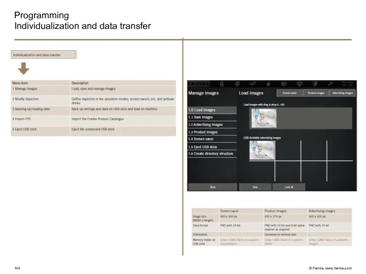
- 104. Programming Individualization and data transfer
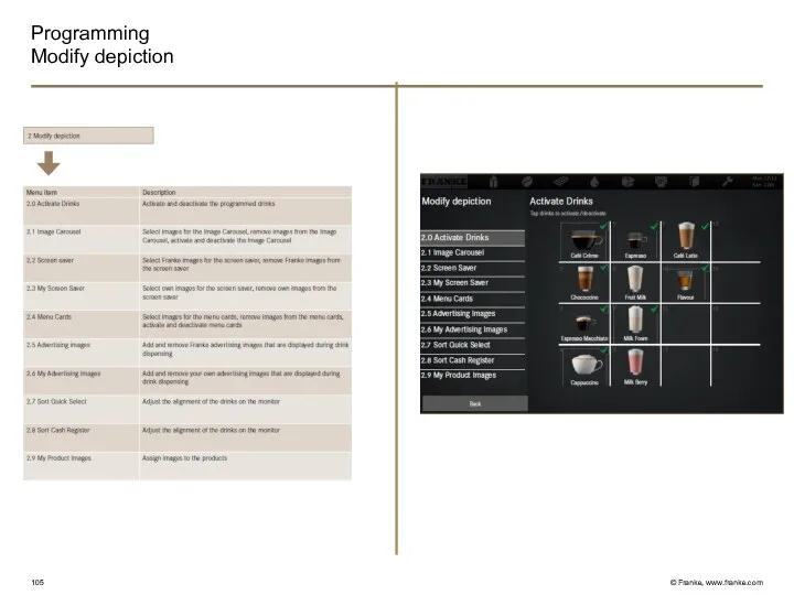
- 105. Programming Modify depiction
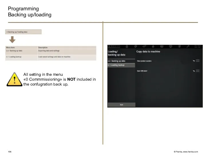
- 106. Programming Backing up/loading All setting in the menu «0 Commmissioning» is NOT included in the confugration
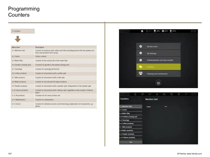
- 107. Programming Counters
- 108. A600 Accessibility components Commissioning Product adjustement Trouble shooting Cleaning
- 109. Questions? QUESTIONS?
- 111. Скачать презентацию
A600
Everything for a perfect coffee
Intro
A600
Everything for a perfect coffee
Intro
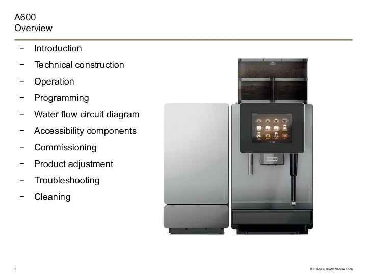
A600
Overview
Introduction
Technical construction
Operation
Programming
Water flow circuit diagram
Accessibility components
Commissioning
Product adjustment
Troubleshooting
Cleaning
A600
Overview
Introduction
Technical construction
Operation
Programming
Water flow circuit diagram
Accessibility components
Commissioning
Product adjustment
Troubleshooting
Cleaning
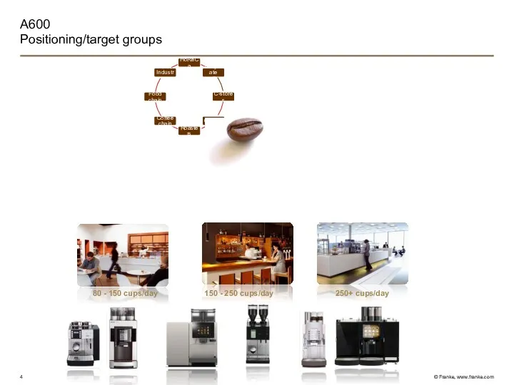
A600
Positioning/target groups
150 - 250 cups/day
80 - 150 cups/day
250+ cups/day
A600
Positioning/target groups
150 - 250 cups/day
80 - 150 cups/day
250+ cups/day
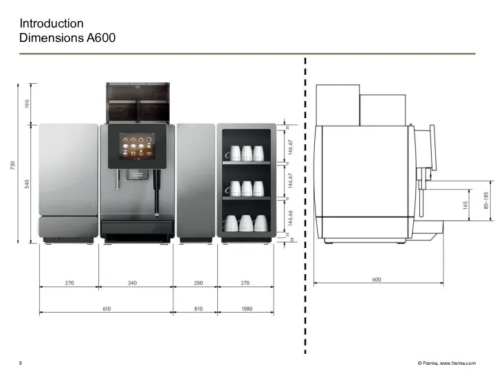
Introduction
Dimensions A600
Introduction
Dimensions A600
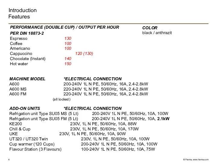
Introduction
Features
PERFORMANCE (DOUBLE CUP) / OUTPUT PER HOUR
PER DIN 18873-2
Espresso 130
Coffee
Introduction
Features
PERFORMANCE (DOUBLE CUP) / OUTPUT PER HOUR
PER DIN 18873-2
Espresso 130
Coffee
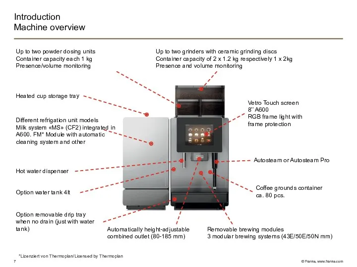
Introduction
Machine overview
Up to two powder dosing units
Container capacity each 1 kg
Presence/volume
Introduction
Machine overview
Up to two powder dosing units
Container capacity each 1 kg
Presence/volume
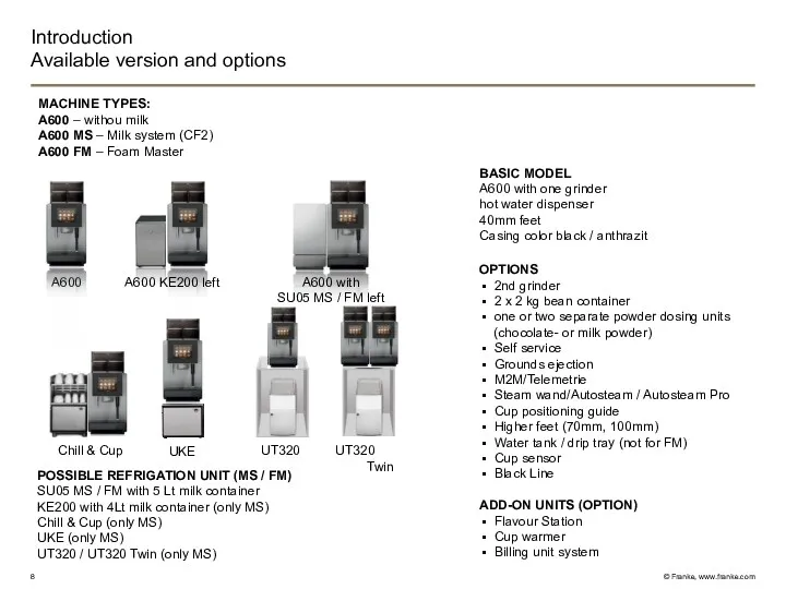
Introduction
Available version and options
MACHINE TYPES:
A600 – withou milk
A600 MS – Milk
Introduction
Available version and options
MACHINE TYPES:
A600 – withou milk
A600 MS – Milk
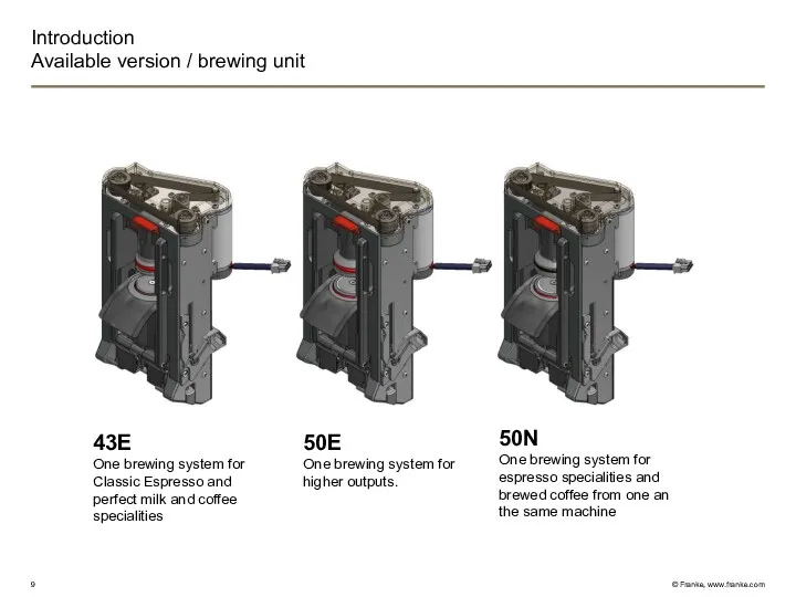
Introduction
Available version / brewing unit
43E
One brewing system for
Classic Espresso and
Introduction
Available version / brewing unit
43E
One brewing system for
Classic Espresso and
Introduction
Model code
Example A600 model code: A600 FM 2G 1P H1 S2
Introduction
Model code
Example A600 model code: A600 FM 2G 1P H1 S2
Introduction
Scope of delivery
Grinder adjusting
Water connection gasket
Cleaning brush
Key
Operating instruction
Cleaning tablets
Cleaning solution
Cleaning brushes
Microfiber
Introduction
Scope of delivery
Grinder adjusting
Water connection gasket
Cleaning brush
Key
Operating instruction
Cleaning tablets
Cleaning solution
Cleaning brushes
Microfiber
Introduction
Hygiene
Short milk tubes between refrigerator and coffee machine
Milk pumps in the
Introduction
Hygiene
Short milk tubes between refrigerator and coffee machine
Milk pumps in the
Introduction
Vetro Touch
VETRO TOUCH SCREEN
The A600 machines are equipped with a 8
Introduction
Vetro Touch
VETRO TOUCH SCREEN
The A600 machines are equipped with a 8
Introduction
The 4 operating modes
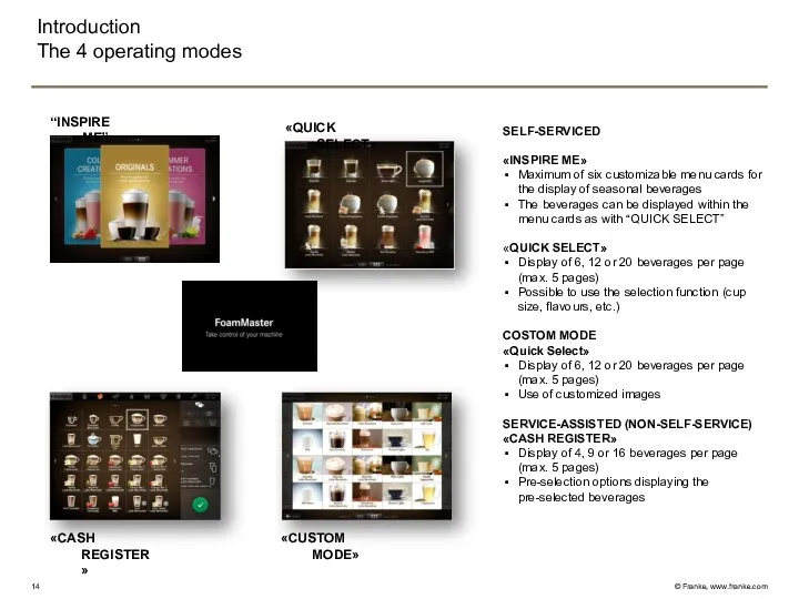
SELF-SERVICED
«INSPIRE ME»
Maximum of six customizable menu cards
Introduction
The 4 operating modes
SELF-SERVICED
«INSPIRE ME»
Maximum of six customizable menu cards
Introduction
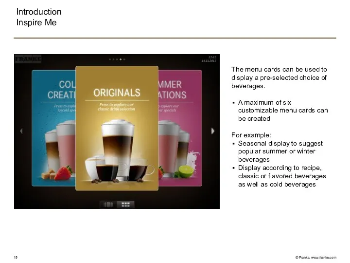
Inspire Me
The menu cards can be used to display a pre-selected
Introduction
Inspire Me
The menu cards can be used to display a pre-selected
Introduction
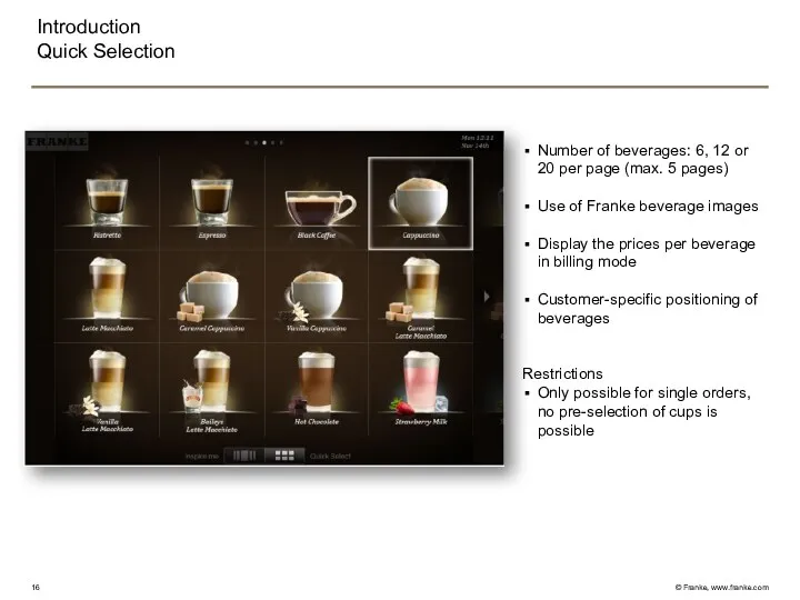
Quick Selection
Number of beverages: 6, 12 or 20 per page (max.
Introduction
Quick Selection
Number of beverages: 6, 12 or 20 per page (max.
Introduction
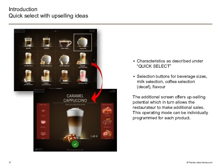
Quick select with upselling ideas
Characteristics as described under “QUICK SELECT”
Selection buttons
Introduction
Quick select with upselling ideas
Characteristics as described under “QUICK SELECT”
Selection buttons
Introduction
Cash Register
Number of beverages: 4, 9 or 16 per page (max.
Introduction
Cash Register
Number of beverages: 4, 9 or 16 per page (max.
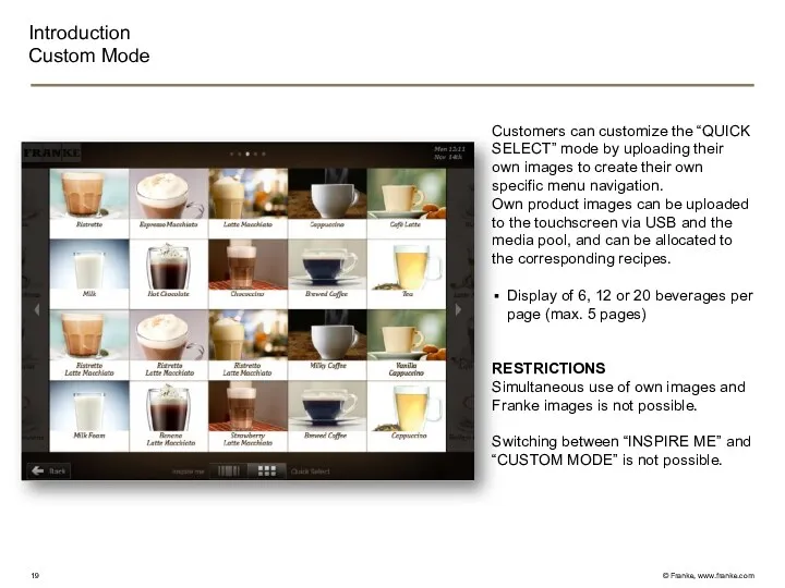
Customers can customize the “QUICK SELECT” mode by uploading their own
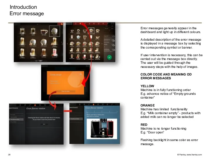
Error messages generally appear in the dashboard and light up in
Error messages generally appear in the dashboard and light up in
Technical construction
Overview
Water flow circuit diagram TS/MS/FM
Water connection
Pump
Flowmeter
Valves (Plastic)
Heating unit‘s TS/MS/FM
Cold water
Technical construction
Overview
Water flow circuit diagram TS/MS/FM
Water connection
Pump
Flowmeter
Valves (Plastic)
Heating unit‘s TS/MS/FM
Cold water
Technical construction
Water flow circuit diagram TS
Back
Technical construction
Water flow circuit diagram TS
Back
Technical construction
Water flow circuit diagram MS
Back
Technical construction
Water flow circuit diagram MS
Back
Technical construction
Water flow circuit diagram FM*
Back
*Lizenziert von Thermoplan/Licensed by Thermoplan
Technical construction
Water flow circuit diagram FM*
Back
*Lizenziert von Thermoplan/Licensed by Thermoplan
Technical construction
Water connection
Y33
Water flow
Electrical
filter
Filter
RV
RV
Flowmeter
X202
X202
Pressure main water
80-800Pa
0.8 – 8 bar
Option water
container
wt
wt
Technical construction
Water connection
Y33
Water flow
Electrical
filter
Filter
RV
RV
Flowmeter
X202
X202
Pressure main water
80-800Pa
0.8 – 8 bar
Option water
container
wt
wt
Technical construction
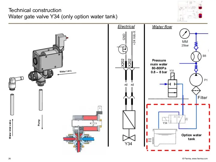
Water gate valve Y34 (only option water tank)
Electrical
Water flow
Filter
X202
X202
rt
Technical construction
Water gate valve Y34 (only option water tank)
Electrical
Water flow
Filter
X202
X202
rt
Technical construction
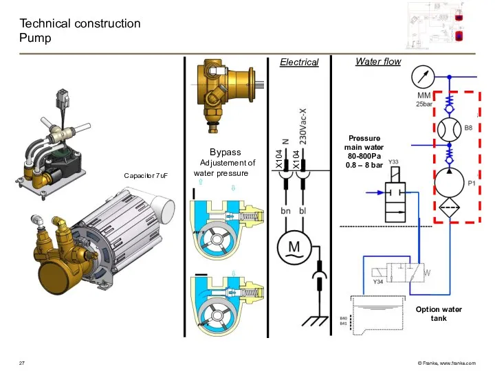
Pump
Bypass
Adjustement of water pressure
Electrical
Water flow
X104
X104
Capacitor 7uF
Pressure main water
80-800Pa
0.8
Technical construction
Pump
Bypass
Adjustement of water pressure
Electrical
Water flow
X104
X104
Capacitor 7uF
Pressure main water
80-800Pa
0.8
Technical construction
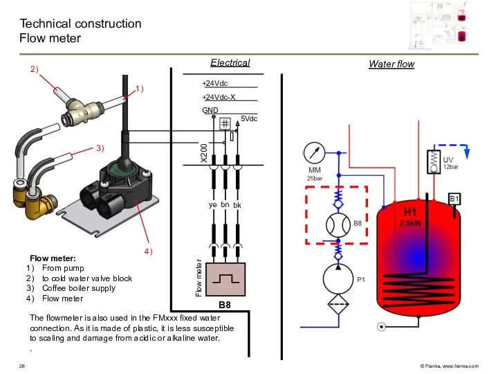
Flow meter
Flow meter:
From pump
to cold water valve block
Coffee boiler supply
Flow
Technical construction
Flow meter
Flow meter:
From pump
to cold water valve block
Coffee boiler supply
Flow
Technical construction
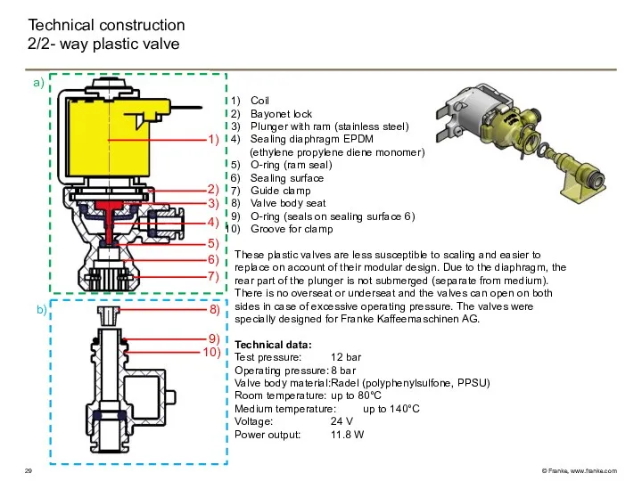
2/2- way plastic valve
1)
2)
3)
4)
6)
5)
7)
9)
10)
a)
b)
8)
Coil
Bayonet lock
Plunger with ram (stainless steel)
Sealing diaphragm
Technical construction
2/2- way plastic valve
1)
2)
3)
4)
6)
5)
7)
9)
10)
a)
b)
8)
Coil
Bayonet lock
Plunger with ram (stainless steel)
Sealing diaphragm
Technical construction
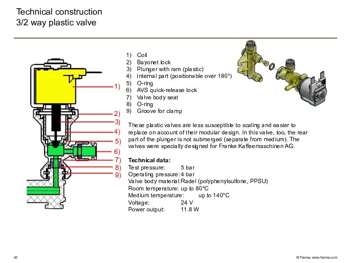
3/2 way plastic valve
1)
2)
3)
4)
6)
5)
7)
8)
9)
Coil
Bayonet lock
Plunger with ram (plastic)
Internal part (positionable
Technical construction
3/2 way plastic valve
1)
2)
3)
4)
6)
5)
7)
8)
9)
Coil
Bayonet lock
Plunger with ram (plastic)
Internal part (positionable
Technical construction
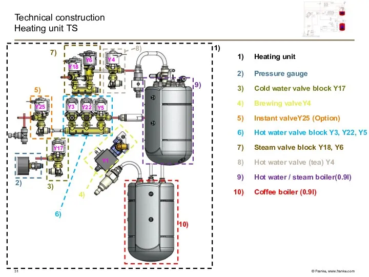
Heating unit TS
6)
9)
10)
2)
7)
8)
3)
1)
4)
5)
Y1
Y4
Y17
Y5
Y22
Y3
Y25
Y6
Y18
Heating unit
Pressure gauge
Cold water valve block Y17
Brewing
Technical construction
Heating unit TS
6)
9)
10)
2)
7)
8)
3)
1)
4)
5)
Y1
Y4
Y17
Y5
Y22
Y3
Y25
Y6
Y18
Heating unit
Pressure gauge
Cold water valve block Y17
Brewing
Technical construction
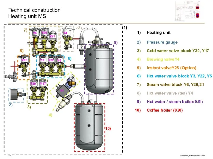
Heating unit MS
6)
9)
10)
2)
7)
8)
3)
1)
4)
5)
Y1
Y4
Y17
Y5
Y22
Y3
Y25
Y6
Y20
Y30
Y21
Heating unit
Pressure gauge
Cold water valve block Y30,
Technical construction
Heating unit MS
6)
9)
10)
2)
7)
8)
3)
1)
4)
5)
Y1
Y4
Y17
Y5
Y22
Y3
Y25
Y6
Y20
Y30
Y21
Heating unit
Pressure gauge
Cold water valve block Y30,
Technical construction
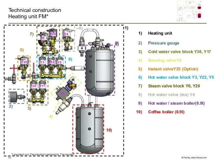
Heating unit FM*
Heating unit
Pressure gauge
Cold water valve block Y30, Y17
Brewing
Technical construction
Heating unit FM*
Heating unit
Pressure gauge
Cold water valve block Y30, Y17
Brewing
Technical construction
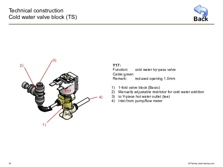
Cold water valve block (TS)
Y17:
Function: cold water by-pass valve
Cable: green
Remark: reduced opening 1.0mm
1-fold
Technical construction
Cold water valve block (TS)
Y17:
Function: cold water by-pass valve
Cable: green
Remark: reduced opening 1.0mm
1-fold
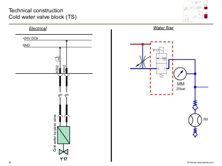
Technical construction
Cold water valve block (TS)
GND
+24V DCs
X202
X202
gn
gn
Y17
Water flow
Electrical
Cold water by-pass valve
Technical construction
Cold water valve block (TS)
GND
+24V DCs
X202
X202
gn
gn
Y17
Water flow
Electrical
Cold water by-pass valve
Technical construction
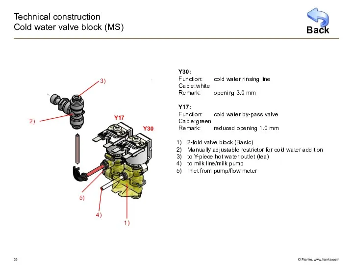
Cold water valve block (MS)
Y30:
Function: cold water rinsing line
Cable: white
Remark: opening 3.0 mm
Y17:
Function: cold water
Technical construction
Cold water valve block (MS)
Y30:
Function: cold water rinsing line
Cable: white
Remark: opening 3.0 mm
Y17:
Function: cold water

Technical construction
Cold water valve block (MS)
GND
+24V DCs
X202
X202
gn
gn
Water flow
Electrical
Y17
X203
X203
rd
rd
Y30
Cold water by-pass valve
Cold
Technical construction
Cold water valve block (MS)
GND
+24V DCs
X202
X202
gn
gn
Water flow
Electrical
Y17
X203
X203
rd
rd
Y30
Cold water by-pass valve
Cold

Technical construction
Cold water valve block (FM*)
Y17
2)
1)
3)
4)
Y30
5)
Back
*Lizenziert von Thermoplan/Licensed by Thermoplan
Y30:
Function: cold water
Technical construction
Cold water valve block (FM*)
Y17
2)
1)
3)
4)
Y30
5)
Back
*Lizenziert von Thermoplan/Licensed by Thermoplan
Y30:
Function: cold water
Technical construction
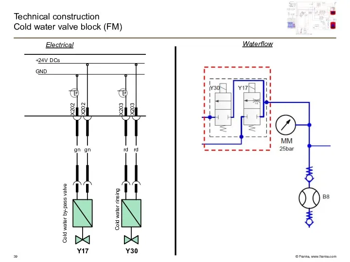
Cold water valve block (FM)
Waterflow
GND
+24V DCs
X202
X202
gn
gn
Electrical
Y17
X203
X203
rd
rd
Y30
Cold water rinsing
Cold water by-pass
Technical construction
Cold water valve block (FM)
Waterflow
GND
+24V DCs
X202
X202
gn
gn
Electrical
Y17
X203
X203
rd
rd
Y30
Cold water rinsing
Cold water by-pass
Technical construction
Coffee boiler 2.5kW (0.9l)
Safety valve12 bar (Spectra)
NTC temperature sensor
Coffee
Technical construction
Coffee boiler 2.5kW (0.9l)
Safety valve12 bar (Spectra)
NTC temperature sensor
Coffee
Technical construction
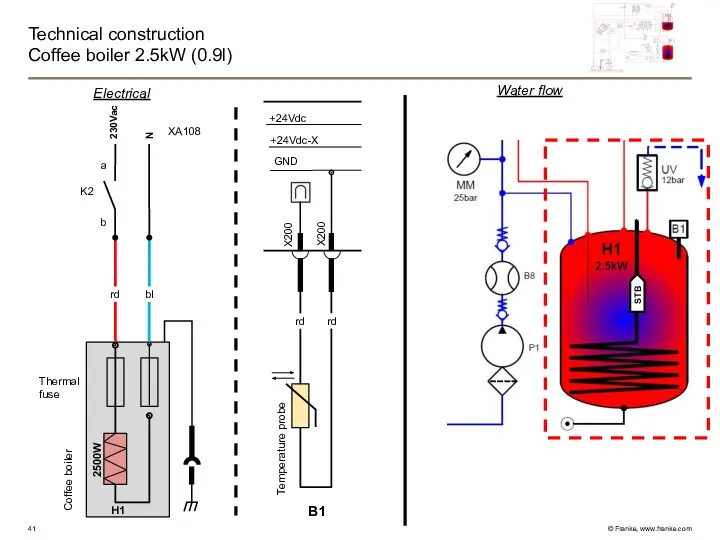
Coffee boiler 2.5kW (0.9l)
Electrical
N
rd
H1
bl
K2
b
a
Thermal
fuse
2500W
230Vac
Coffee boiler
XA108
B1
STB
GND
+24Vdc-X
+24Vdc
X200
X200
rd
rd
Temperature probe
Water flow
Technical construction
Coffee boiler 2.5kW (0.9l)
Electrical
N
rd
H1
bl
K2
b
a
Thermal
fuse
2500W
230Vac
Coffee boiler
XA108
B1
STB
GND
+24Vdc-X
+24Vdc
X200
X200
rd
rd
Temperature probe
Water flow
Technical construction
Hot water valve block (TS, MS, FM)
Hot water valve block:
Y3:
Function: bypass
Technical construction
Hot water valve block (TS, MS, FM)
Hot water valve block:
Y3:
Function: bypass
Technical construction
Hot water valve block (TS, MS, FM)
GND
+24V DCs
X202
X202
X203
X203
X202
X202
ye
ye
rd
rd
gr
gr
Y5
Y22
Y3
Electrical
Sanitizing
Bypass valve coffee
Hot
Technical construction
Hot water valve block (TS, MS, FM)
GND
+24V DCs
X202
X202
X203
X203
X202
X202
ye
ye
rd
rd
gr
gr
Y5
Y22
Y3
Electrical
Sanitizing
Bypass valve coffee
Hot
Technical construction
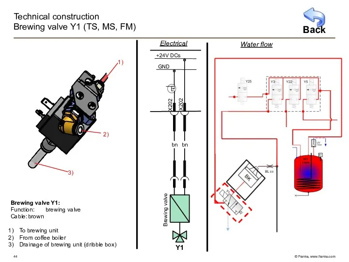
Brewing valve Y1 (TS, MS, FM)
GND
+24V DCs
Electrical
X202
X202
bn
bn
Y1
Brewing valve
1)
2)
3)
Brewing valve Y1:
Function: brewing
Technical construction
Brewing valve Y1 (TS, MS, FM)
GND
+24V DCs
Electrical
X202
X202
bn
bn
Y1
Brewing valve
1)
2)
3)
Brewing valve Y1:
Function: brewing
Technical construction
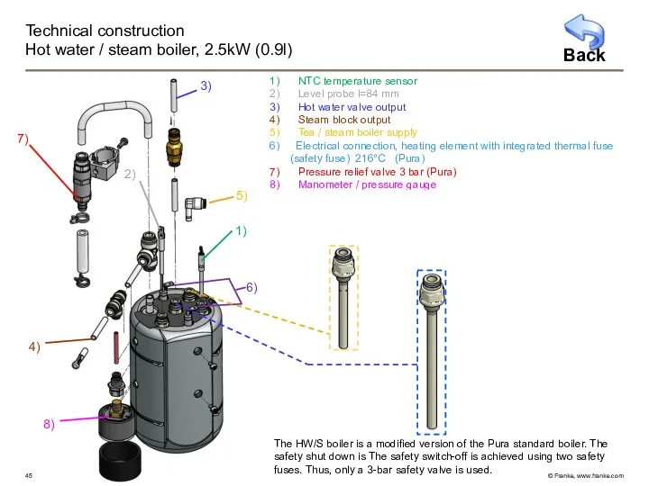
Hot water / steam boiler, 2.5kW (0.9l)
NTC temperature sensor
Level probe
Technical construction
Hot water / steam boiler, 2.5kW (0.9l)
NTC temperature sensor
Level probe
Technical construction
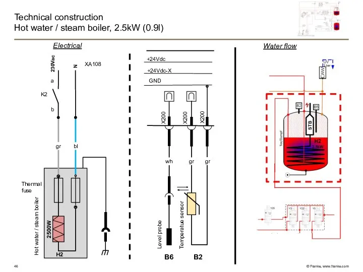
Hot water / steam boiler, 2.5kW (0.9l)
STB
Water flow
Electrical
N
gr
H2
bl
K2
b
a
Thermal
fuse
2500W
GND
+24Vdc-X
+24Vdc
B2
X200
X200
gr
gr
wh
B6
X200
230Vac
Hot water
Technical construction
Hot water / steam boiler, 2.5kW (0.9l)
STB
Water flow
Electrical
N
gr
H2
bl
K2
b
a
Thermal
fuse
2500W
GND
+24Vdc-X
+24Vdc
B2
X200
X200
gr
gr
wh
B6
X200
230Vac
Hot water
Technische Konstruktion
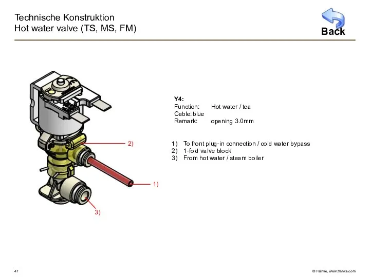
Hot water valve (TS, MS, FM)
1)
2)
3)
Y4:
Function: Hot water / tea
Cable: blue
Remark: opening 3.0mm
To
Technische Konstruktion
Hot water valve (TS, MS, FM)
1)
2)
3)
Y4:
Function: Hot water / tea
Cable: blue
Remark: opening 3.0mm
To
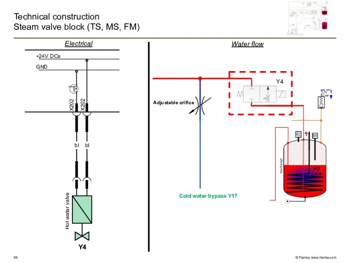
Technical construction
Steam valve block (TS, MS, FM)
GND
+24V DCs
X202
X202
bl
bl
Y4
Electrical
Hot water valve
Cold water
Technical construction
Steam valve block (TS, MS, FM)
GND
+24V DCs
X202
X202
bl
bl
Y4
Electrical
Hot water valve
Cold water
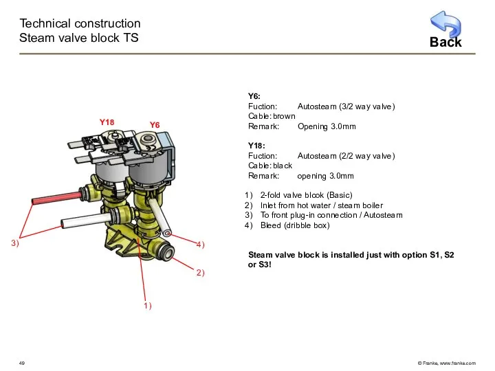
Technical construction
Steam valve block TS
Y6:
Fuction: Autosteam (3/2 way valve)
Cable: brown
Remark: Opening 3.0mm
Y18:
Fuction: Autosteam (2/2 way
Technical construction
Steam valve block TS
Y6:
Fuction: Autosteam (3/2 way valve)
Cable: brown
Remark: Opening 3.0mm
Y18:
Fuction: Autosteam (2/2 way
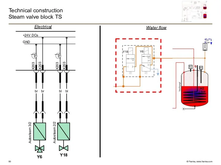
Technical construction
Steam valve block TS
GND
+24V DCs
X203
X203
X203
X203
br
br
bl
bl
Electrical
Autosteam 3/2
Autosteam 2/2
Y18
Y6
Water flow
Technical construction
Steam valve block TS
GND
+24V DCs
X203
X203
X203
X203
br
br
bl
bl
Electrical
Autosteam 3/2
Autosteam 2/2
Y18
Y6
Water flow
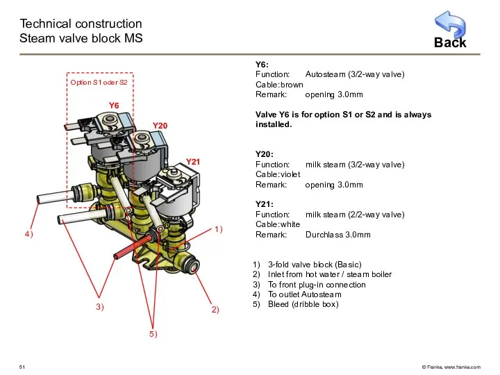
Technical construction
Steam valve block MS
Y6:
Function: Autosteam (3/2-way valve)
Cable: brown
Remark: opening 3.0mm
Valve Y6 is for
Technical construction
Steam valve block MS
Y6:
Function: Autosteam (3/2-way valve)
Cable: brown
Remark: opening 3.0mm
Valve Y6 is for
Technical construction
Steam valve block MS
GND
+24V DCs
X203
X203
X203
X203
br
br
vi
vi
Autosteam
Milk Steam 3/2
Y20
Y6
X203
X203
wh
wh
Milk Steam 2/2
Y21
Water flow
Electrical
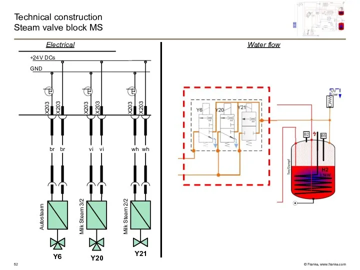
Technical construction
Steam valve block MS
GND
+24V DCs
X203
X203
X203
X203
br
br
vi
vi
Autosteam
Milk Steam 3/2
Y20
Y6
X203
X203
wh
wh
Milk Steam 2/2
Y21
Water flow
Electrical
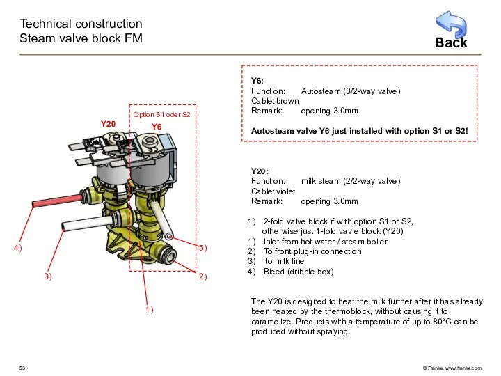
Technical construction
Steam valve block FM
Y6:
Function: Autosteam (3/2-way valve)
Cable: brown
Remark: opening 3.0mm
Autosteam valve Y6 just
Technical construction
Steam valve block FM
Y6:
Function: Autosteam (3/2-way valve)
Cable: brown
Remark: opening 3.0mm
Autosteam valve Y6 just
Technical construction
Steam valve block FM
GND
+24V DCs
X203
X203
X203
X203
br
br
vi
vi
Electrical
Autosteam
Steam valve
Y20
Y6
Water flow
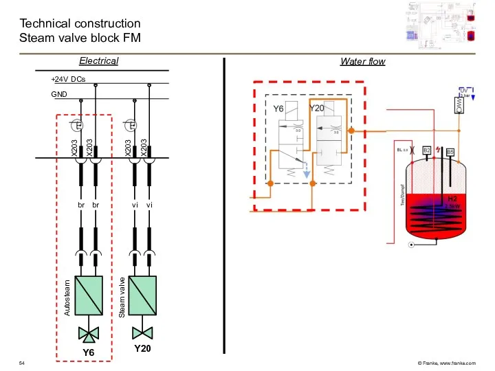
Technical construction
Steam valve block FM
GND
+24V DCs
X203
X203
X203
X203
br
br
vi
vi
Electrical
Autosteam
Steam valve
Y20
Y6
Water flow
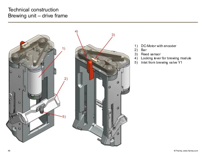
Technical construction
Brewing unit – drive frame
DC-Motor with encoder
Bar
Reed sensor
Locking lever for
Technical construction
Brewing unit – drive frame
DC-Motor with encoder
Bar
Reed sensor
Locking lever for
Technical construction
Brewing unit – brewing module 43E / 50E / 50N
43E
50N
50E
From
Technical construction
Brewing unit – brewing module 43E / 50E / 50N
43E
50N
50E
From
Technical construction
Brewing unit – brewing module 43E / 50E / 50N
Ejection
Technical construction
Brewing unit – brewing module 43E / 50E / 50N
Ejection
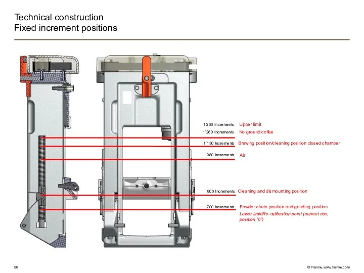
Lower limit/Re-calibration point (current rise, position “0”)
Cleaning and dismounting position
Powder chute
Lower limit/Re-calibration point (current rise, position “0”)
Cleaning and dismounting position
Powder chute
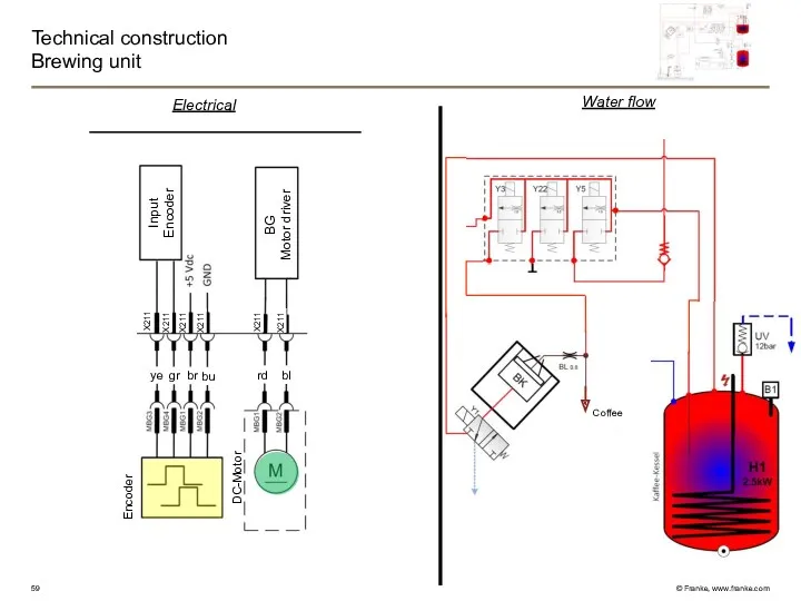
Technical construction
Brewing unit
Coffee
Water flow
Electrical
Encoder
DC-Motor
rd
bl
ye
gr
br
bu
sw
bl
rt
X211
X211
X211
X211
X211
X211
Technical construction
Brewing unit
Coffee
Water flow
Electrical
Encoder
DC-Motor
rd
bl
ye
gr
br
bu
sw
bl
rt
X211
X211
X211
X211
X211
X211
Technical construction
Coffee outlet TS / MS / FM
Distributor FM:
Milk
Coffee
Instant
Coffee outlet:
Outlet
Technical construction
Coffee outlet TS / MS / FM
Distributor FM:
Milk
Coffee
Instant
Coffee outlet:
Outlet
Technical construction
Front door
Electrical
Outlet
Motor
GND
+24Vdc-X
+24Vdc
Outlet DC-Motor
bl
rt
Outlet DC-Motor 24VDC
Print for panel
Gear wheel to outlet
Air
Technical construction
Front door
Electrical
Outlet
Motor
GND
+24Vdc-X
+24Vdc
Outlet DC-Motor
bl
rt
Outlet DC-Motor 24VDC
Print for panel
Gear wheel to outlet
Air
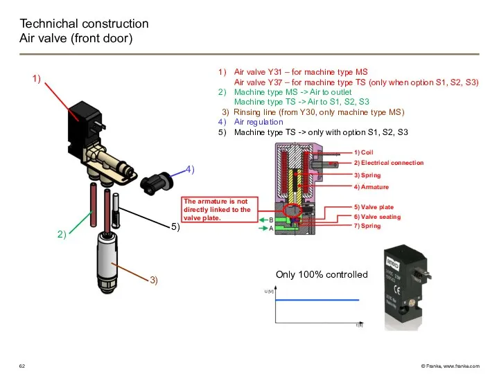
Technichal construction
Air valve (front door)
Air valve Y31 – for machine type
Technichal construction
Air valve (front door)
Air valve Y31 – for machine type
Technical construction
Instant mixer (Option)
1)
2)
3)
Mixer chamber
Mixer motor
Extractor housing
Fan
Filter
Condensation container
4)
5)
6)
Y25
Hot water
Technical construction
Instant mixer (Option)
1)
2)
3)
Mixer chamber
Mixer motor
Extractor housing
Fan
Filter
Condensation container
4)
5)
6)
Y25
Hot water
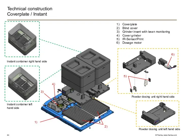
Pulverdosierer rechts
Technical construction
Coverplate / Instant
Coverplate
Blind cover
Grinder insert with bean monitoring
Cover grinder
IR-Sensor/Print
Dosage
Pulverdosierer rechts
Technical construction
Coverplate / Instant
Coverplate
Blind cover
Grinder insert with bean monitoring
Cover grinder
IR-Sensor/Print
Dosage
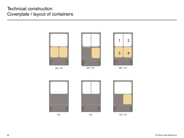
Technical construction
Coverplate / layout of containers
1
2
3
4
Technical construction
Coverplate / layout of containers
1
2
3
4
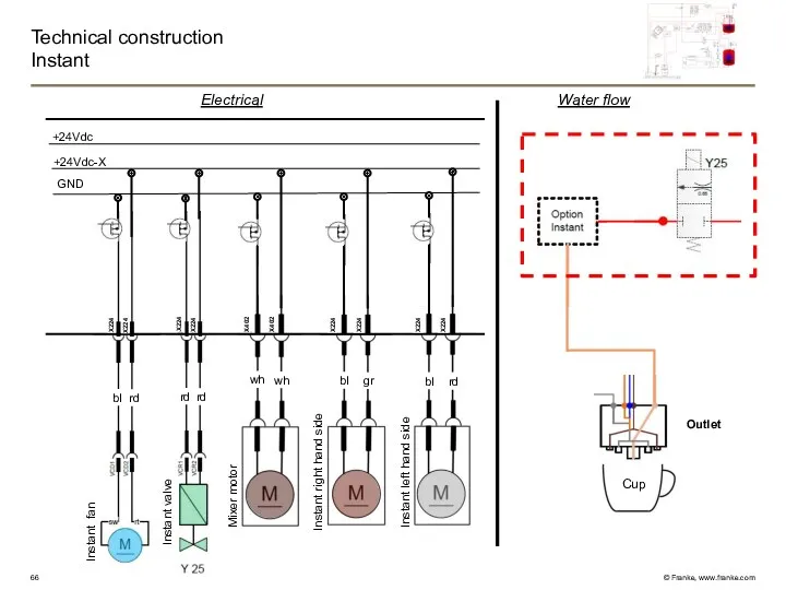
Technical construction
Instant
Electrical
GND
+24Vdc-X
+24Vdc
Instant fan
Instant valve
Mixer motor
Instant right hand side
Instant
Technical construction
Instant
Electrical
GND
+24Vdc-X
+24Vdc
Instant fan
Instant valve
Mixer motor
Instant right hand side
Instant
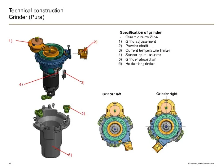
Technical construction
Grinder (Pura)
Grinder right
Mühle links
1)
2)
3)
4)
6)
5)
Specification of grinder:
- Ceramic burrs Ø 54
Technical construction
Grinder (Pura)
Grinder right
Mühle links
1)
2)
3)
4)
6)
5)
Specification of grinder:
- Ceramic burrs Ø 54
Technical construction
Grinder / Adjustement
A) Standard position for use with the Pura
Technical construction
Grinder / Adjustement
A) Standard position for use with the Pura
Technichal construction
Electronics / electrical box
Switch-mode power supply
L I/O Print
Semiconductor relays (Boiler)
Process
Technichal construction
Electronics / electrical box
Switch-mode power supply
L I/O Print
Semiconductor relays (Boiler)
Process
Technical construction
Electronics / Process PCB
X200 -
X202 -
X203 -
X205 -
X206 -
X208 -
Technical construction
Electronics / Process PCB
X200 -
X202 -
X203 -
X205 -
X206 -
X208 -
Technical construction
Electronics / Power I/O Print
XM101 -
XM102 -
X104 -
X109 -
X110 -
X111
Technical construction
Electronics / Power I/O Print
XM101 -
XM102 -
X104 -
X109 -
X110 -
X111
Technical construction
Electronics / semiconductor relays (coffee and HW/S boiler)
Design and functionality
The
Technical construction
Electronics / semiconductor relays (coffee and HW/S boiler)
Design and functionality
The
Technical construction
Electronics / switch-mode power supply
X1 -
X3 -
X4 -
F1-
Power supply from
Technical construction
Electronics / switch-mode power supply
X1 -
X3 -
X4 -
F1-
Power supply from
Technical construction
Operator panel / vetro touch 8 inch
Panel complete
connection panel
Panel
Edge lighting
UI
Technical construction
Operator panel / vetro touch 8 inch
Panel complete
connection panel
Panel
Edge lighting
UI
Technical construction
Milk system and Foam Master* Module
*Lizenziert von Thermoplan/Licensed by Thermoplan
FM
Technical construction
Milk system and Foam Master* Module
*Lizenziert von Thermoplan/Licensed by Thermoplan
FM
Technical construction
Milk system MS
Milk intake MS:
Milk intake valveY38
Inline sensor
Milk intake
Gear pump
Technical construction
Milk system MS
Milk intake MS:
Milk intake valveY38
Inline sensor
Milk intake
Gear pump
Technical construction
Milk system MS / gear pump
Construction and functionality
The gear pump
Technical construction
Milk system MS / gear pump
Construction and functionality
The gear pump
Technical construction
FM* Module
*Lizenziert von Thermoplan/Licensed by Thermoplan
Technical construction
FM* Module
*Lizenziert von Thermoplan/Licensed by Thermoplan
Technical construction
Slide in module FM*
Water flow
Milk valve Y46 (warm)
Gear pump (P10)
Milk
Technical construction
Slide in module FM*
Water flow
Milk valve Y46 (warm)
Gear pump (P10)
Milk
Technical construction
Slide in module FM* / Thermoblock
Thermoblock (2000Watt)
Isolation Thermoblock R
Isolation Thermoblock
Technical construction
Slide in module FM* / Thermoblock
Thermoblock (2000Watt)
Isolation Thermoblock R
Isolation Thermoblock
Technical construction
Thermoblock (only FM*)
Water flow
Electrical
230Vac
N
sw
H3
bl
K3
b
a
Thermal fuse
2000W
GND
+24Vdc-X
+24Vdc
Milk print
B3
X801
X801
vt
vt
Thermoblock
Temperatue sensor
*Lizenziert von Thermoplan/Licensed by
Technical construction
Thermoblock (only FM*)
Water flow
Electrical
230Vac
N
sw
H3
bl
K3
b
a
Thermal fuse
2000W
GND
+24Vdc-X
+24Vdc
Milk print
B3
X801
X801
vt
vt
Thermoblock
Temperatue sensor
*Lizenziert von Thermoplan/Licensed by
Technical construction
Slide in module FM* / gear pump & air pulse
Technical construction Slide in module FM* / gear pump & air pulse
Technical construction
Cleaning agent detection and peristaltic pump FM* Modul
Cleaning agent detection
Technical construction
Cleaning agent detection and peristaltic pump FM* Modul
Cleaning agent detection
Technical construction
Container SU / FM* Modul
Milk container cpl. (5 Liter)
Cleaning container
Technical construction
Container SU / FM* Modul
Milk container cpl. (5 Liter)
Cleaning container
Technical construction
Easy Compact
Access parameter:
Keep pressing "Set" button till "PS" is appearing
Select
Technical construction
Easy Compact
Access parameter:
Keep pressing "Set" button till "PS" is appearing
Select
Technical construction
FM* module print
Semiconductor relais
Cleaning pumpe
Gear pumpe
Valve Milk warm Y46
Valve Milk
Technical construction
FM* module print
Semiconductor relais
Cleaning pumpe
Gear pumpe
Valve Milk warm Y46
Valve Milk
Technical construction
Flavour Station (Option)
Electrical part
Peristaltic pump
Drawer
Connection / sliding part
2)
1)
3)
4)
Technical construction
Flavour Station (Option)
Electrical part
Peristaltic pump
Drawer
Connection / sliding part
2)
1)
3)
4)
Technical construction
Flavour Station / electrical part
Function
The switching power supply is supplied
Technical construction
Flavour Station / electrical part
Function
The switching power supply is supplied
Technical construction
Flavour Station / electrical part
P1
P3
P2
24 VDC
USB
CAN
Priming- Button
Fuse
ON OFF
54 CAN Bus 53
6 Pumps 3
0 Chocco 1
0 Chocco 1
0 Chocco 1
0 Chocco 1
0 Pump return 1
1 Pump return 0
0
Technical construction
Flavour Station / electrical part
P1
P3
P2
24 VDC
USB
CAN
Priming- Button
Fuse
ON OFF
54 CAN Bus 53
6 Pumps 3
0 Chocco 1
0 Chocco 1
0 Chocco 1
0 Chocco 1
0 Pump return 1
1 Pump return 0
0
Technical construction
Flavour Station / mechanical part
Stepper motor
Coupling
Supporter for the motor
Peristaltic pump
Cover
Technical construction
Flavour Station / mechanical part
Stepper motor
Coupling
Supporter for the motor
Peristaltic pump
Cover
Technical construction
Flavour Station / Function of the pump
Technical construction
Flavour Station / Function of the pump
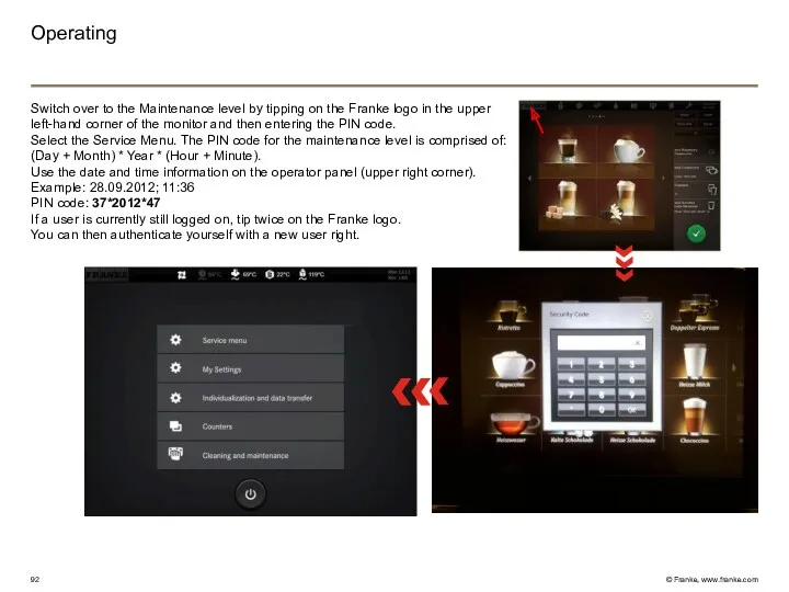
Operating
Switch over to the Maintenance level by tipping on the Franke
Operating
Switch over to the Maintenance level by tipping on the Franke
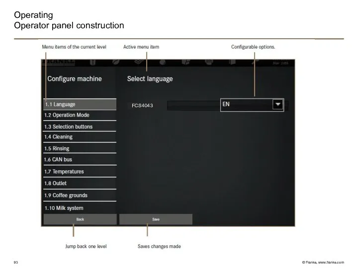
Operating
Operator panel construction
FCS4043
Operating
Operator panel construction
FCS4043
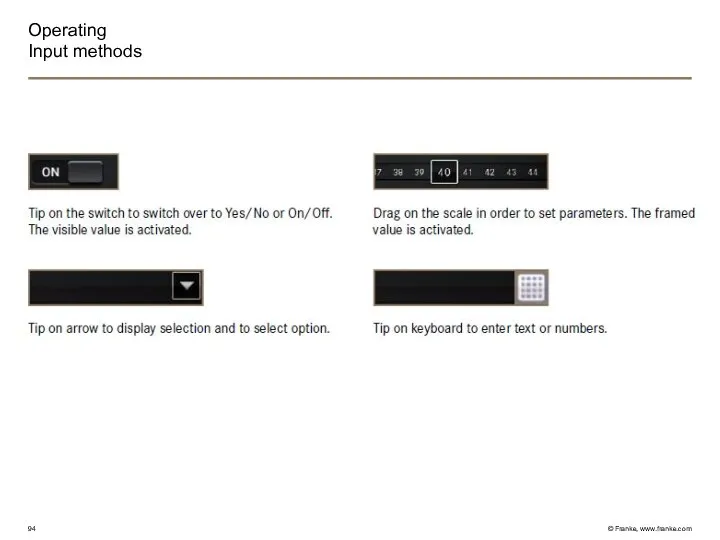
Operating
Input methods
Operating
Input methods
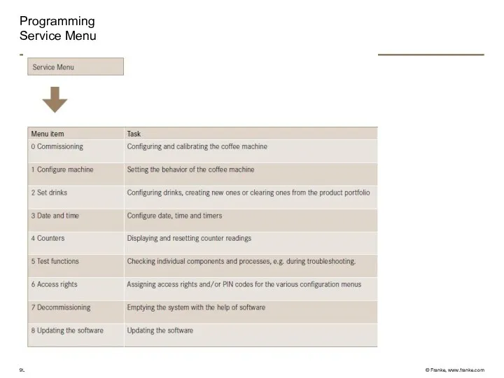
Programming
Service Menu
Programming
Service Menu
Programming
Commissioning
FCS4026
Programming
Commissioning
FCS4026
Programming
Configure machine
FCS4026
Programming
Configure machine
FCS4026
Programming
Set Drinks
Programming
Set Drinks
Programming
Date and Time
Programming
Date and Time
Programming
Test functions
Programming
Test functions
Programming
Access rights
Programming
Access rights
Programming
Decommissioning
Programming
Decommissioning
Programming
Updating the software
Programming
Updating the software
Programming
Individualization and data transfer
Programming
Individualization and data transfer
Programming
Modify depiction
Programming
Modify depiction
Programming
Backing up/loading
All setting in the menu
«0 Commmissioning» is NOT included
Programming
Backing up/loading
All setting in the menu
«0 Commmissioning» is NOT included
Programming
Counters
Programming
Counters
A600
Accessibility components
Commissioning
Product adjustement
Trouble shooting
Cleaning
A600
Accessibility components
Commissioning
Product adjustement
Trouble shooting
Cleaning
Questions?
QUESTIONS?
Questions?
QUESTIONS?
 Письмо по электронной почте от микроба Лентяйкина
 ГИА. Вопрос А3. Химическая связь
 Открытые переломы, гнойные осложнения переломов, травматический остеомиелит, современные методы лечения открытых переломов
 Тайны яблока
 Анализ ликвидности и платежеспособности организации на основе бухгалтерской отчетности на примере ООО Вертикаль
 Программа работы с одаренными детьми
 методическая разработка интегрированного урока по предмету Численные методы и Основы алгоритмизации и программирования
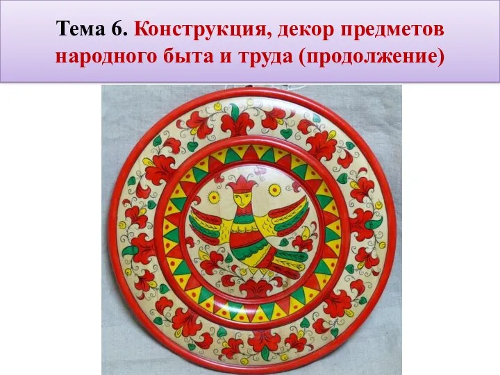 20240123_izo_5_klass._tema_6._konstruktsiya_i_dekor_predmetov_narodnogo_byta
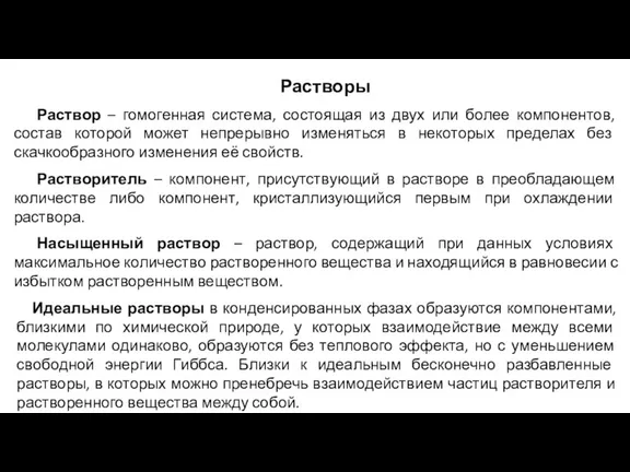 лекция_Растворы
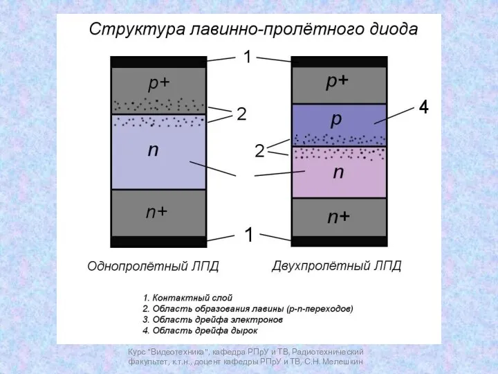 Лавинно-пролётный диод. Диод Ганна
 Кубические и биквадратные уравнения
 Источники трудового права
 Артикуляционная гимнастика с обезьянкой Соней
 Презентация Покормите птиц зимой
 Геометрические фигуры (для дошкольников)
 Химия. Образовательные программы магистратуры
 Тұрақты стенокардия
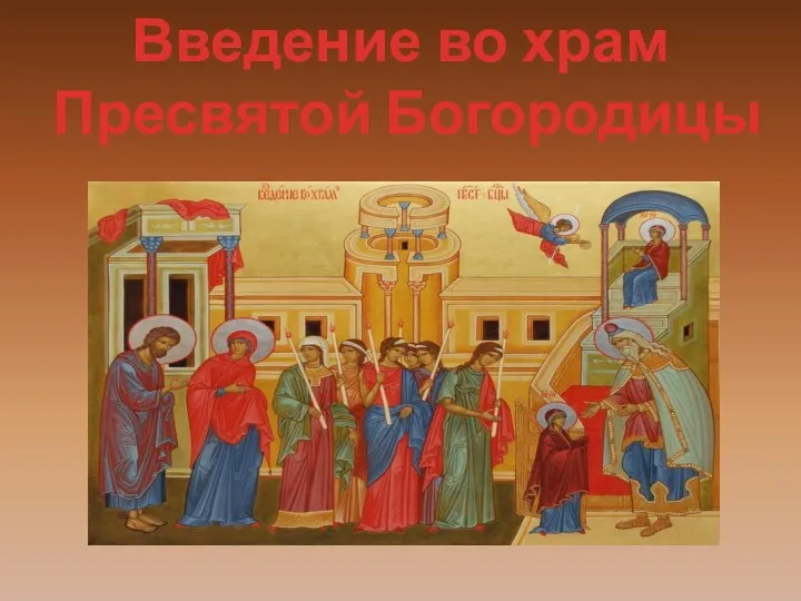 Введение во храм Пресвятой Богородицы
 Использование нетрадиционной техники на занятиях Юный художник
 Рекламная кампания. Планирование и организация
 Буквенная запись свойств сложения и вычитания
 Карстовые процессы
 Девиантное поведение детей и подростков – виды, причины, феноменология
 Инфологическое моделирование
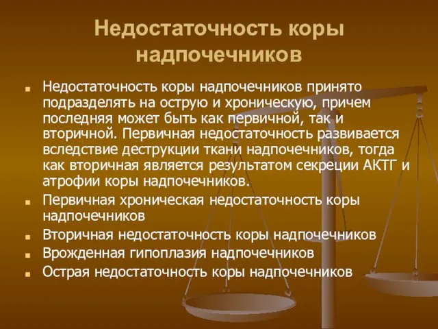 Недостаточность коры надпочечников
 Потребитель и его права
 Динамическое проектирование систем стабилизации летательных аппаратов. Исполнительные устройства. Рулевой привод
 В здоровом теле - здоровый дух