- CM D-2.2L Engine

Содержание
- 2. EURO III vs EURO IV Developmental target for emission ① EURO-4 emission reduction potential compared with
- 3. SCV(Swirl Control Valve) λ sensor CPF Diff pressure & Temp sensor ACV(Air Control Valve) 2nd GEN
- 4. Comparative table ( EURO-III vs EURO-IV)
- 5. D-2.0L vs D-2.2L
- 6. Input / output (EURO-III and EURO-IV) APS 1, 2 Brake, clutch S/W CKPS & CMPS Boost
- 7. EURO-IV injection SOE (Start Of Energizing) ET (Energizing Time)
- 8. Burning procedure for diesel engine Flame depending on pilot injection or not Without pilot injection With
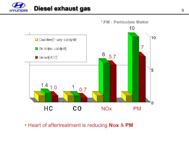
- 9. 1.4 1 6 10 7 5.7 0.7 1.0 NOx PM * PM : Particulate Matter Heart
- 10. CPF (Catalyzed Particulate Filter)
- 11. What is PM (Particulate Material or Matter) Specialty Definition: PARTICULATE MATTER Energy Unburned fuel particles that
- 12. Components of PM SOL (Solid fraction) : elemental carbon / ash SOF (soluble organic fraction) :
- 13. Kinds of catalystic converter depending on location MCC (Manifold Catalytic Converter) CCC (Close-Coupled Catalytic Converter) WCC
- 14. Washcoat Substrate Catalystic converter terms
- 15. Pd : Purify HC mainly. Thermal resistance is good. Using in CCC using as Pd only
- 16. Selective Catalyst Poisoning Catalyst Fouling Catalyst Sintering Washcoat Sintering Selective Catalyst Poisoning poisoning by Pb, Hg,
- 17. LNT (Lean NOx Trap) SCR (Selective Catalytic Reduction) DOC (Diesel Oxidation Catalyst) DPF (Diesel Particulate Filter)
- 18. PM reducing device
- 19. Efective to reduce CO/HC and SOF (SO2 is changed to sulfate)) ** SOF(Soluble Organic Fraction) PAH(polycyclic
- 20. ● Principle (1) Trapping the PM(Particulate Material) (2) Burnig the trapped PM at regular driving distance
- 21. CPF passive soot regeneration ** Passive : without any additive mechanism Active : with additive mechanism
- 22. CPF active soot regeneration Increasing temp. of exhaust gas through post injection and DOC ? burning
- 23. Filter Squre pillar Filter: Trapping & regeneration DOC: Improve condition of PM regeneration Temp sensor: checking
- 24. CRDi ECU DOC 머플러 Pressure /temp sensor Post injection Fuel pump High pressure pump CRDi ENG
- 25. 1. Accumulating ash Regeneration procedure
- 26. sensor ECU INJ pump 2. Increasing exhaust pressure & post injection Regeneration procedure
- 27. ` CO2+Heat CO2+Heat CO2+Heat CO2+Heat CO2+Heat 3. PM regeneration Exhaust temp is increased by post injection
- 28. 4. re-accumulating ash Ash is accumulated by unburned fuel/oil How fast ash is accumulated in the
- 29. KM & JM exhaust system overview Diff pressure sensor Temp sensor Air gap insulator pipe Main
- 30. Regeneration mode condition Drving distance: every 1,000km Engine RPM: 1,000RPM ~ 4,000RPM Engine load: around 0.7bar(
- 31. Low speed Mid/high speed Safety Diff pressure SOOT volume SIMULATION Driving distance Regeneration method
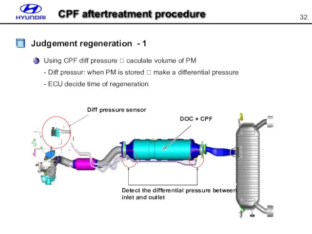
- 32. Judgement regeneration - 1 Using CPF diff pressure ? caculate volume of PM - Diff pressur:
- 33. Differential pressure model
- 34. Judge by driving distance - Every 1,000km , ECU decide regeneration Maybe regeneration is going because
- 35. Predict the volume of PM by using simulation Detect the volume of accumulated PM depending on
- 36. Simulation model
- 37. Burning PM by increasing temp up to 550℃~600℃ Regeneration Inter cooler ACV (Air control valve) EGR
- 38. CPF component Differential pressure sensor Diff sensor Diff pipe CPF output(V) 4.5 1 0 100 pressure(kPa)
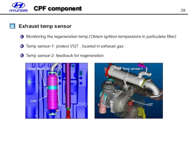
- 39. CPF component Exhaust temp sensor Monitoring the regeneration temp.(Obtain ignition temperature in particulate filter) Temp sensor-1:
- 40. Adapted vehicle : D-RS, D-JM, D-KM, D-NF, D-MG, D-UN, D-CMAT, D-TGAT, D-FO, U-FCAT 2007 EUR DOM
- 41. CPF service regeneration by Hi-scan
- 42. EURO-IV Additional MENU for CPF T3/T5 temperature CPF service regeneration by Hi-scan
- 43. Component change routine (ECU change) Notice) If you change some parts related CPF you should do
- 44. IN THIS MODE, CAN RESET THE DISTANCE OF LAST CHANGED CPF AND OTHERS RELATED PARAMETERS. PRESS
- 45. Current data SCV & ACV actuator Outlet & inlet pressure sensor T3 & T5 temp sensor
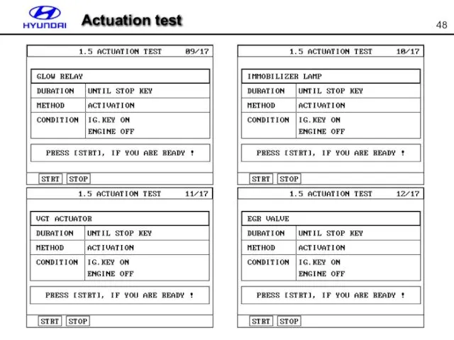
- 46. Actuation test
- 47. Actuation test
- 48. Actuation test
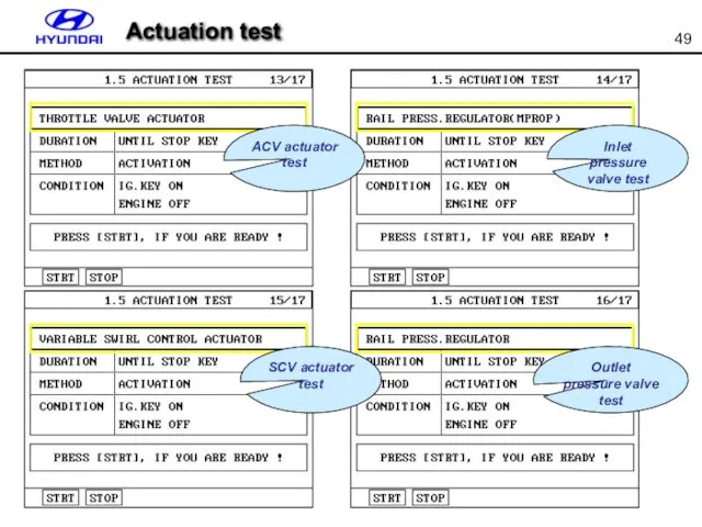
- 49. Actuation test Inlet pressure valve test ACV actuator test Outlet pressure valve test SCV actuator test
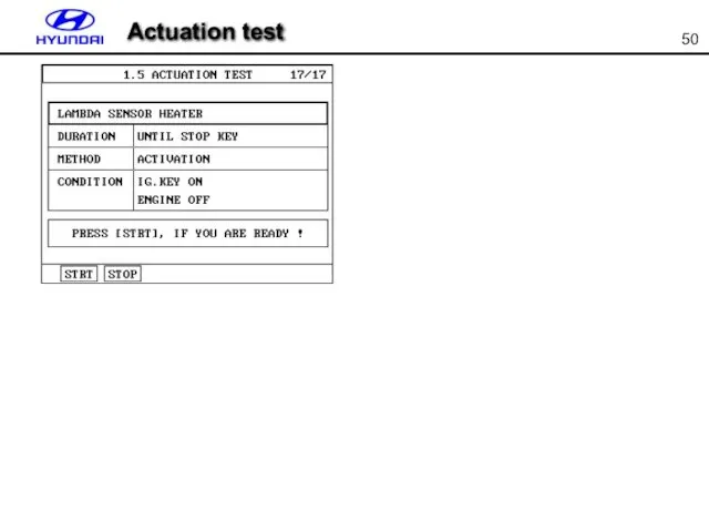
- 50. Actuation test
- 51. Injection correction (IQA) Enter the 7-digit code
- 53. Скачать презентацию
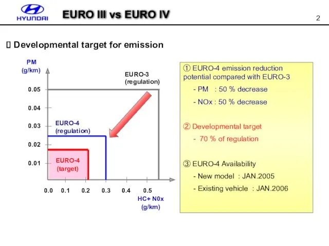
EURO III vs EURO IV
Developmental target for emission
① EURO-4
EURO III vs EURO IV
Developmental target for emission
① EURO-4
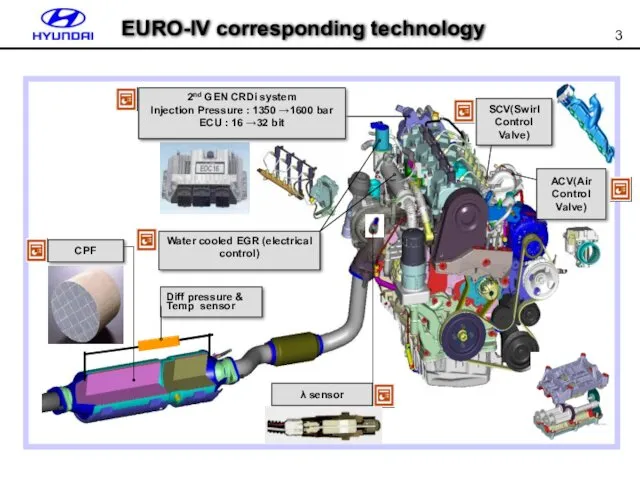
SCV(Swirl Control Valve)
λ sensor
CPF
Diff pressure & Temp sensor
ACV(Air Control Valve)
2nd
SCV(Swirl Control Valve)
λ sensor
CPF
Diff pressure & Temp sensor
ACV(Air Control Valve)
2nd
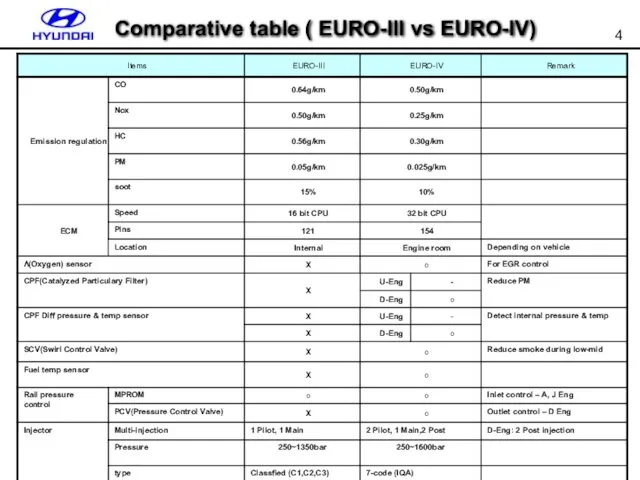
Comparative table ( EURO-III vs EURO-IV)
Comparative table ( EURO-III vs EURO-IV)
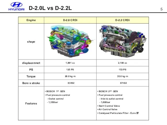
D-2.0L vs D-2.2L
D-2.0L vs D-2.2L
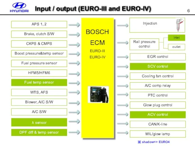
Input / output (EURO-III and EURO-IV)
APS 1, 2
Brake, clutch S/W
CKPS &
Input / output (EURO-III and EURO-IV)
APS 1, 2
Brake, clutch S/W
CKPS &
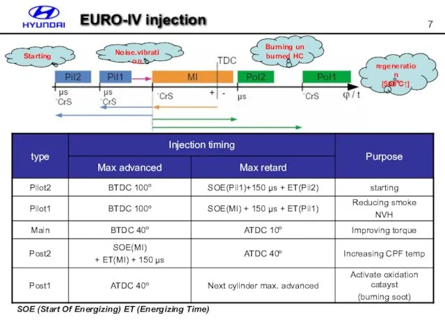
EURO-IV injection
SOE (Start Of Energizing) ET (Energizing Time)
EURO-IV injection
SOE (Start Of Energizing) ET (Energizing Time)
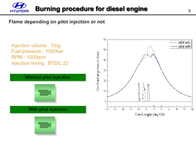
Burning procedure for diesel engine
Flame depending on pilot injection or not
Without
Burning procedure for diesel engine
Flame depending on pilot injection or not
Without
1.4
1
6
10
7
5.7
0.7
1.0
NOx
PM
* PM : Particulate Matter
Heart of aftertreatment is reducing
1.4
1
6
10
7
5.7
0.7
1.0
NOx
PM
* PM : Particulate Matter
Heart of aftertreatment is reducing
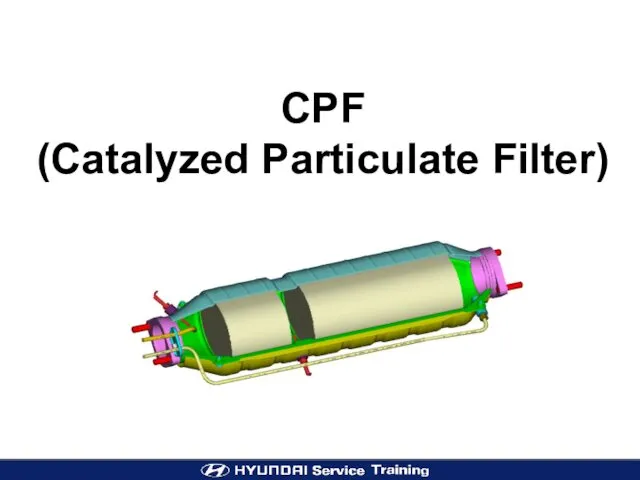
CPF
(Catalyzed Particulate Filter)
CPF
(Catalyzed Particulate Filter)
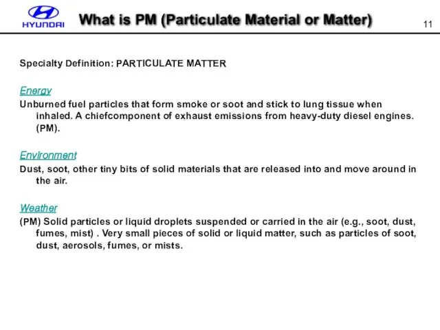
What is PM (Particulate Material or Matter)
Specialty Definition: PARTICULATE MATTER
Energy
Unburned fuel
What is PM (Particulate Material or Matter)
Specialty Definition: PARTICULATE MATTER
Energy
Unburned fuel
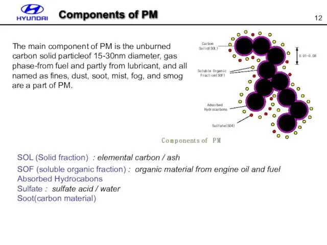
Components of PM
SOL (Solid fraction) : elemental carbon / ash
SOF
Components of PM
SOL (Solid fraction) : elemental carbon / ash
SOF
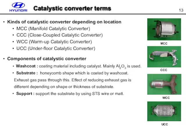
Kinds of catalystic converter depending on location
MCC (Manifold Catalytic
Kinds of catalystic converter depending on location
MCC (Manifold Catalytic
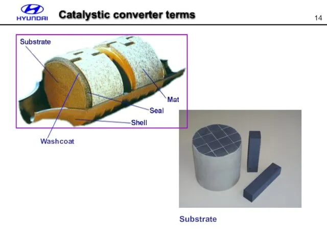
Washcoat
Substrate
Catalystic converter terms
Washcoat
Substrate
Catalystic converter terms
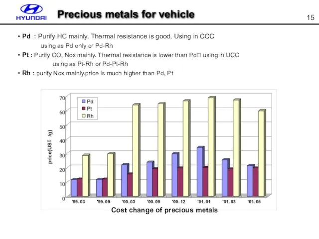
Pd : Purify HC mainly. Thermal resistance is good. Using
Pd : Purify HC mainly. Thermal resistance is good. Using
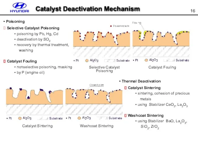
Selective Catalyst Poisoning
Catalyst Fouling
Catalyst Sintering
Washcoat Sintering
Selective Catalyst Poisoning
poisoning by
Selective Catalyst Poisoning
Catalyst Fouling
Catalyst Sintering
Washcoat Sintering
Selective Catalyst Poisoning
poisoning by
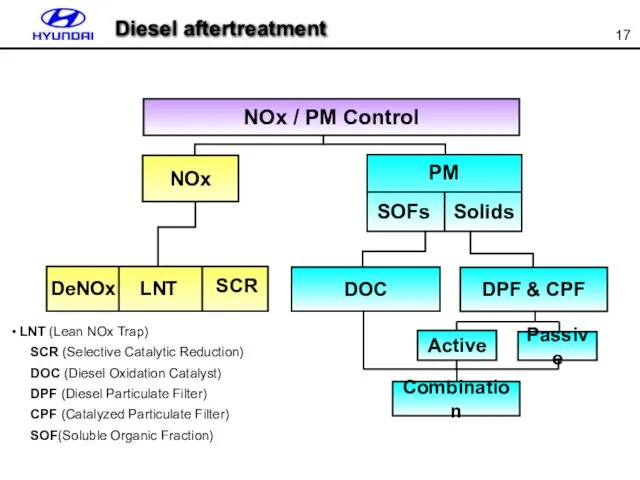
LNT (Lean NOx Trap)
SCR (Selective Catalytic Reduction)
DOC (Diesel
LNT (Lean NOx Trap)
SCR (Selective Catalytic Reduction)
DOC (Diesel
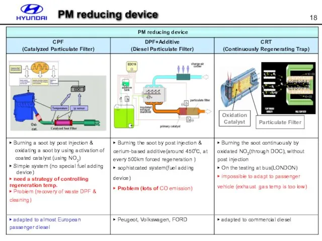
PM reducing device
PM reducing device
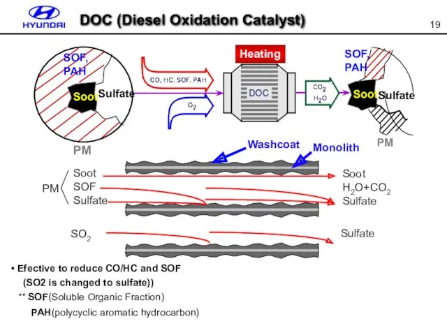
Efective to reduce CO/HC and SOF
(SO2 is changed
Efective to reduce CO/HC and SOF
(SO2 is changed
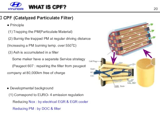
● Principle
(1) Trapping the PM(Particulate Material)
(2) Burnig the trapped
● Principle
(1) Trapping the PM(Particulate Material)
(2) Burnig the trapped
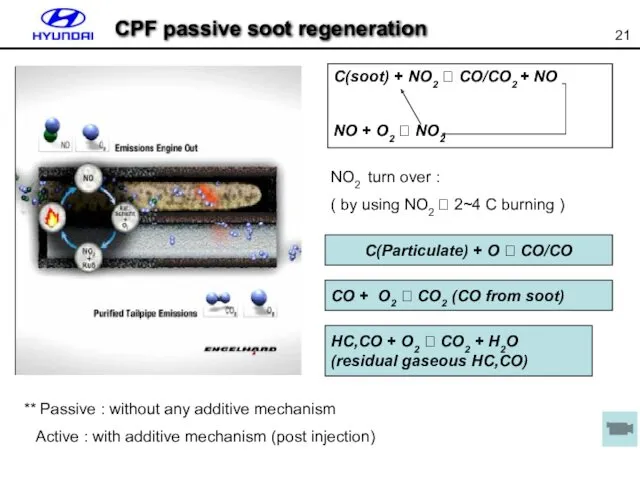
CPF passive soot regeneration
** Passive : without any additive mechanism
CPF passive soot regeneration
** Passive : without any additive mechanism
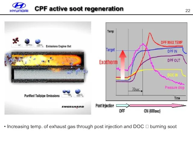
CPF active soot regeneration
Increasing temp. of exhaust gas through
CPF active soot regeneration
Increasing temp. of exhaust gas through
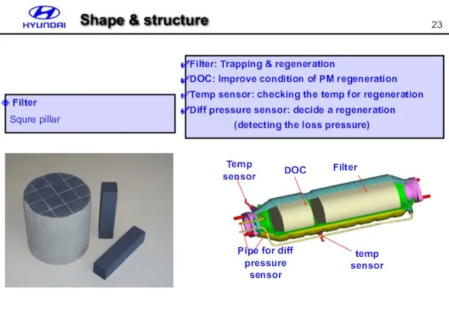
Filter
Squre pillar
Filter: Trapping & regeneration
DOC: Improve condition of PM regeneration
Temp
Filter
Squre pillar
Filter: Trapping & regeneration
DOC: Improve condition of PM regeneration
Temp
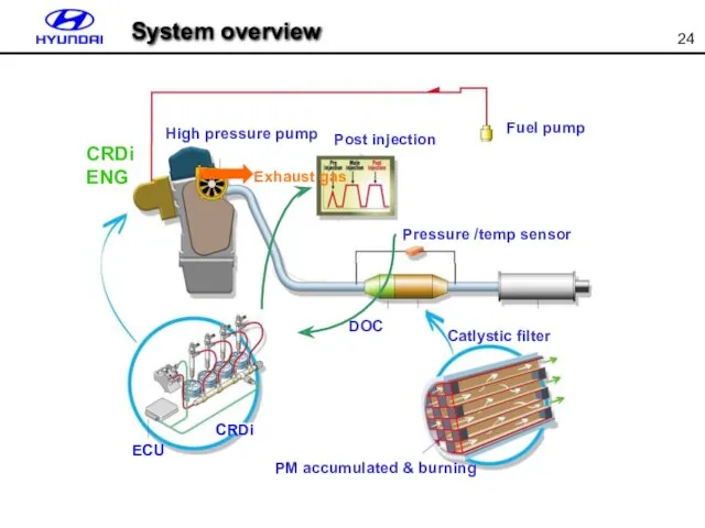
CRDi
ECU
DOC
머플러
Pressure /temp sensor
Post injection
Fuel pump
High pressure pump
CRDi
ENG
Catlystic filter
PM accumulated &
CRDi
ECU
DOC
머플러
Pressure /temp sensor
Post injection
Fuel pump
High pressure pump
CRDi
ENG
Catlystic filter
PM accumulated &

1. Accumulating ash
Regeneration procedure
1. Accumulating ash
Regeneration procedure
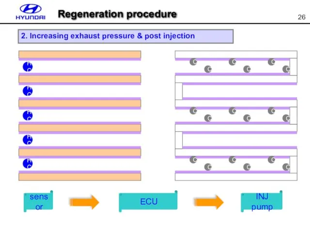
sensor
ECU
INJ pump
2. Increasing exhaust pressure & post injection
Regeneration procedure
sensor
ECU
INJ pump
2. Increasing exhaust pressure & post injection
Regeneration procedure
`
CO2+Heat
CO2+Heat
CO2+Heat
CO2+Heat
CO2+Heat
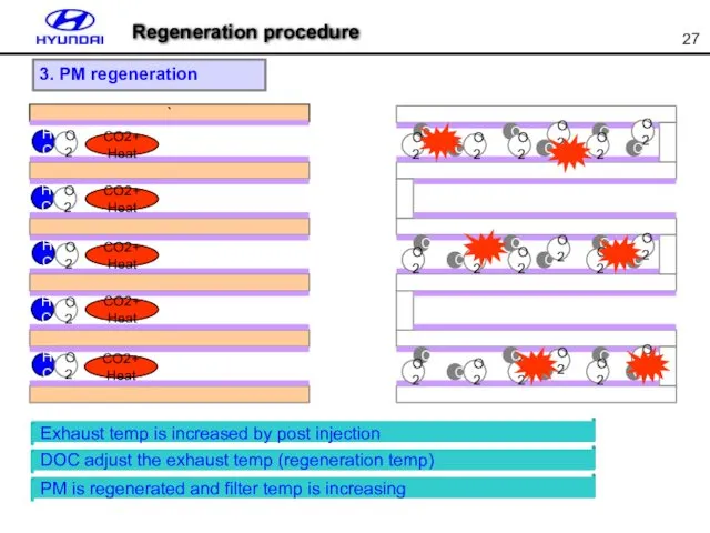
3. PM regeneration
Exhaust temp is increased by post injection
PM is
`
CO2+Heat
CO2+Heat
CO2+Heat
CO2+Heat
CO2+Heat
3. PM regeneration
Exhaust temp is increased by post injection
PM is
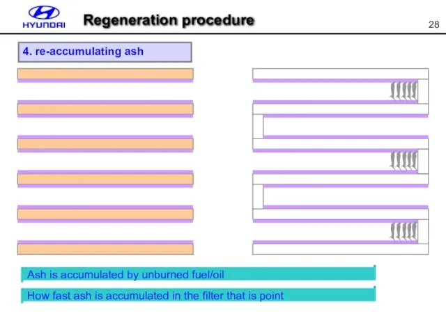
4. re-accumulating ash
Ash is accumulated by unburned fuel/oil
How fast ash
4. re-accumulating ash
Ash is accumulated by unburned fuel/oil
How fast ash
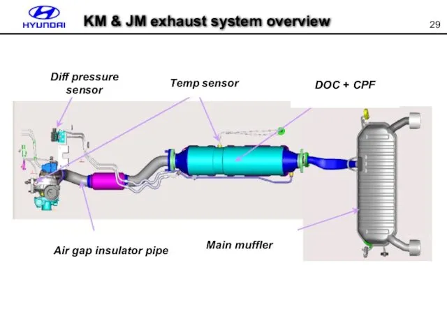
KM & JM exhaust system overview
Diff pressure sensor
Temp sensor
Air gap insulator
KM & JM exhaust system overview
Diff pressure sensor
Temp sensor
Air gap insulator
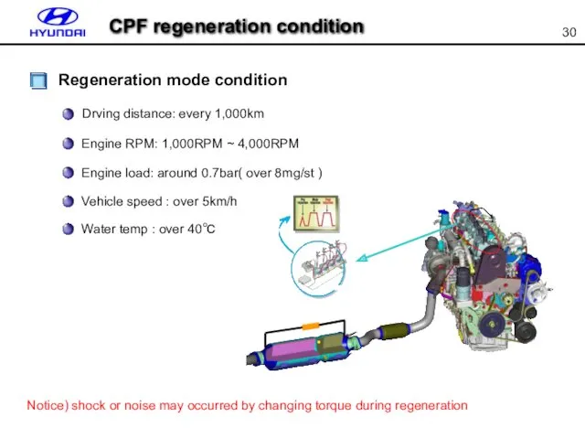
Regeneration mode condition
Drving distance: every 1,000km
Engine RPM: 1,000RPM ~ 4,000RPM
Engine
Regeneration mode condition
Drving distance: every 1,000km
Engine RPM: 1,000RPM ~ 4,000RPM
Engine
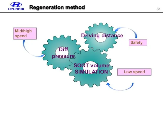
Low speed
Mid/high speed
Safety
Diff pressure
SOOT volume
SIMULATION
Driving distance
Regeneration method
Low speed
Mid/high speed
Safety
Diff pressure
SOOT volume
SIMULATION
Driving distance
Regeneration method
Judgement regeneration - 1
Using CPF diff pressure ? caculate volume of
Judgement regeneration - 1
Using CPF diff pressure ? caculate volume of
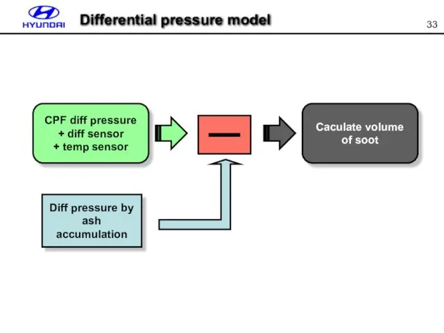
Differential pressure model
Differential pressure model
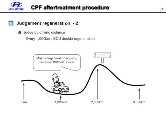
Judge by driving distance
- Every 1,000km , ECU decide regeneration
Maybe regeneration
Judge by driving distance
- Every 1,000km , ECU decide regeneration
Maybe regeneration
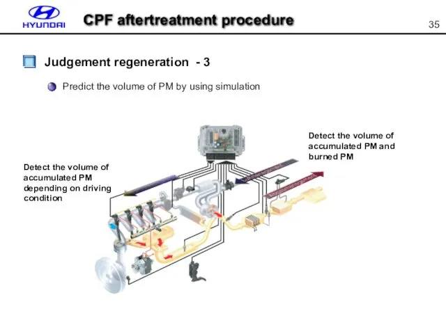
Predict the volume of PM by using simulation
Detect the volume of
Predict the volume of PM by using simulation
Detect the volume of
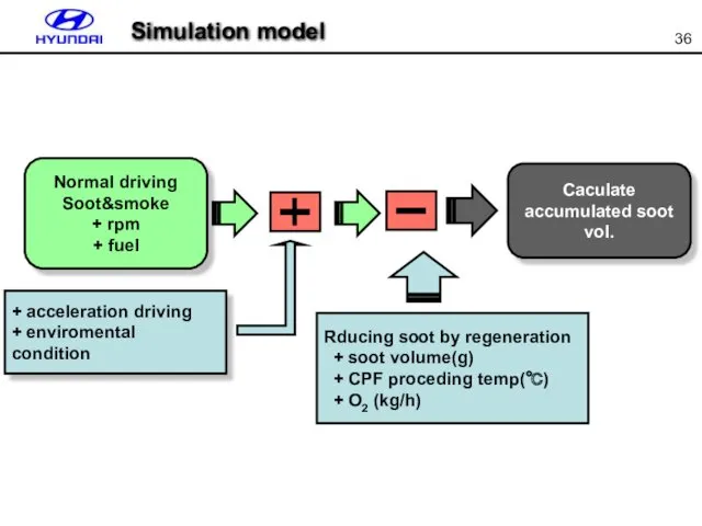
Simulation model
Simulation model
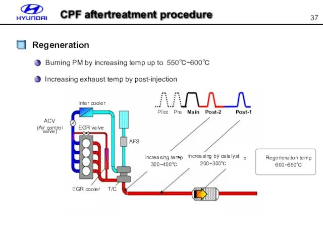
Burning PM by increasing temp up to 550℃~600℃
Regeneration
Inter cooler
ACV
(Air control valve)
EGR
Burning PM by increasing temp up to 550℃~600℃
Regeneration
Inter cooler
ACV
(Air control valve)
EGR
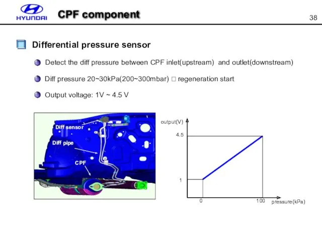
CPF component
Differential pressure sensor
Diff sensor
Diff pipe
CPF
output(V)
4.5
1
0
100
pressure(kPa)
Detect the diff pressure between CPF
CPF component
Differential pressure sensor
Diff sensor
Diff pipe
CPF
output(V)
4.5
1
0
100
pressure(kPa)
Detect the diff pressure between CPF
CPF component
Exhaust temp sensor
Monitoring the regeneration temp.(Obtain ignition temperature in particulate
CPF component
Exhaust temp sensor
Monitoring the regeneration temp.(Obtain ignition temperature in particulate
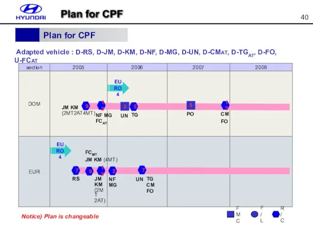
Adapted vehicle : D-RS, D-JM, D-KM, D-NF, D-MG, D-UN, D-CMAT,
Adapted vehicle : D-RS, D-JM, D-KM, D-NF, D-MG, D-UN, D-CMAT,
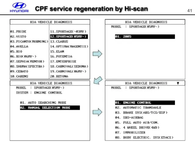
CPF service regeneration by Hi-scan
CPF service regeneration by Hi-scan
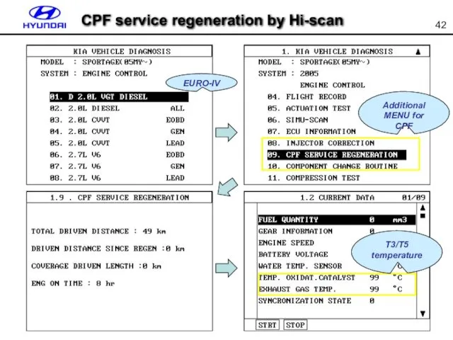
EURO-IV
Additional MENU for CPF
T3/T5 temperature
CPF service regeneration by Hi-scan
EURO-IV
Additional MENU for CPF
T3/T5 temperature
CPF service regeneration by Hi-scan
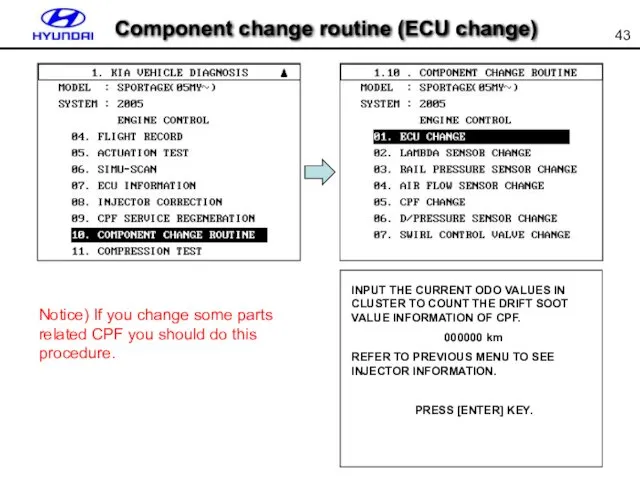
Component change routine (ECU change)
Notice) If you change some parts related
Component change routine (ECU change)
Notice) If you change some parts related
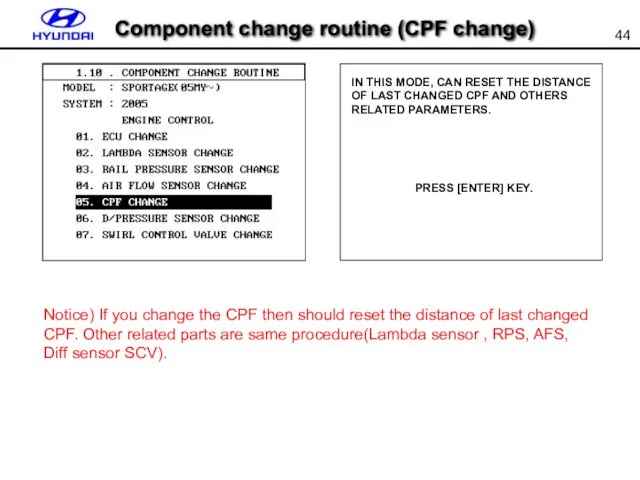
IN THIS MODE, CAN RESET THE DISTANCE OF LAST CHANGED CPF
IN THIS MODE, CAN RESET THE DISTANCE OF LAST CHANGED CPF
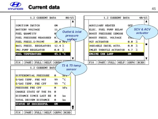
Current data
SCV & ACV actuator
Outlet & inlet pressure sensor
T3 & T5
Current data
SCV & ACV actuator
Outlet & inlet pressure sensor
T3 & T5
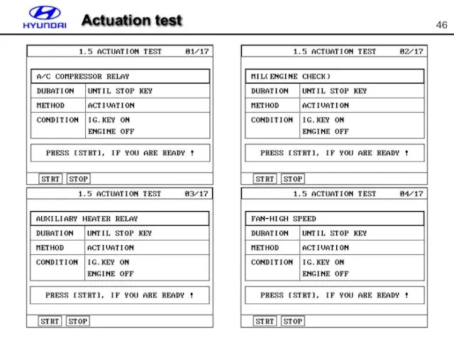
Actuation test
Actuation test

Actuation test
Actuation test
Actuation test
Actuation test
Actuation test
Inlet pressure valve test
ACV actuator test
Outlet pressure valve test
SCV actuator
Actuation test
Inlet pressure valve test
ACV actuator test
Outlet pressure valve test
SCV actuator
Actuation test
Actuation test
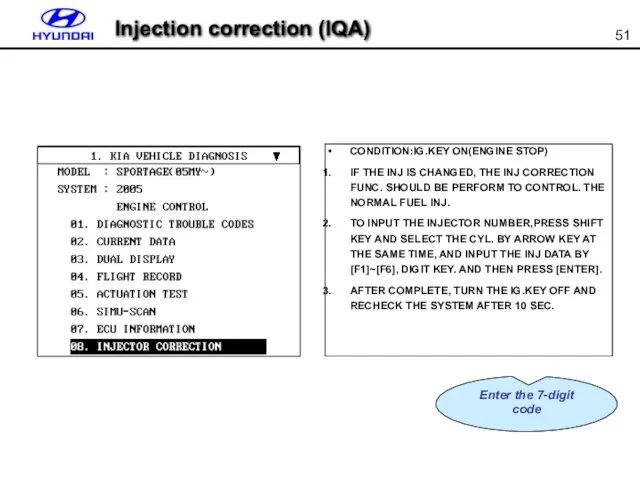
Injection correction (IQA)
Enter the 7-digit
code
Injection correction (IQA)
Enter the 7-digit
code
 Классификация строительных машин
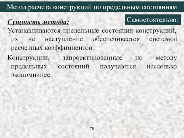 Метод расчета конструкций по предельным состояниям
 Презентация
 Технология обогащения медно-цинковых руд
 HeidelbergCement Kazakhstan. Инструкция для поставщиков. Регистрация на портале EasySupply
 Электроника негіздері. Аналогты және сандық электроника. Аналогты электрониканың элементтері
 Изменения в нормативной базе для НФО (4937-У, 5075-У, 5084-У, 32-ФЗ)
 Шаблон 9 мая. Зима
 презентация Путешествие в страну Светофория
 Скорость прямолинейного равноускоренного движения. График скорости. Перемещение тела при прямолинейном равноускоренном движении
 Я гражданин страны великой
 Оформление библиографического списка к научной работе
 ир звезд
 Презентация: Сказочный мир продленки
 Project work. My favorite and unusual building
 Презентация к уроку технологии Поделка в подарок папе к 23 февраля 3 класс
 Источники права
 Презентация к уроку по теме Кремний
 Боги и люди в Синтоизме
 Prepositions of place
 Принципиальные электрические схемы систем автоматизации
 Презентация по теме Алканы
 Методическая разработка проекта Безопасная дорога детства.
 Диапазоны частот
 Презентация Мама - самый родной и любимый человек
 Характеристика нервової системи тварин та людини
 If You Love Me and You Know It Song
 Чрезвычайные ситуации экологического характера