Compressed elements of constant cross section. Compressed transition elements of constant cross section презентация
- Compressed elements of constant cross section. Compressed transition elements of constant cross section

Содержание
- 2. Pillars are one of the oldest building structures. More than 3,000 years ago, the Egyptians carved
- 3. Parthenon Temple By order of Pericles, B.C. 447 and BC Graduated in 432. There are 8
- 4. Persepolis is an ancient Iranian complex BC 518 Xerxes I graduated from Darius Corridor of a
- 5. The scientific study of the problems of the work of compressible elements began in the XVIII
- 6. Figure 12.1. Medium compressible column. Foundation 1; Base 2; Rod 3; Section 4 Columns are vertical
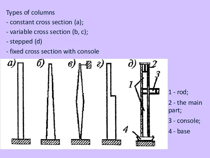
- 7. 1 - rod; 2 - the main part; 3 - console; 4 - base Types of
- 8. by design of rod sections: solid (solid-walled) The main cross section of the compressible elements is
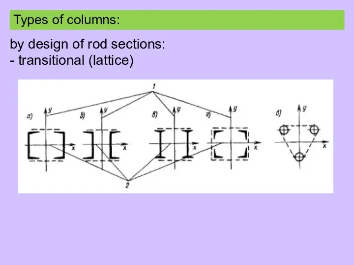
- 9. by design of rod sections: - transitional (lattice) Types of columns:
- 10. The cross-sectional columns are lattice rods (b, c), lattice (d) and perforated (d, e) without independent
- 11. The maximum design load of a transition beam with a cross section of two channels is
- 12. Grids without slopes have a beautiful appearance and are the simplest, so they are often used
- 13. The design scheme of the compressive columns depends on its fastening to the foundation and connection
- 14. The stability of the compressed element should be checked as follows: NEd - calculated value of
- 15. - Class 4 for cross sections where: χ is the reduction factor for the corresponding stability
- 16. α - coefficient taking into account the initial defect; Ncr is the critical force for the
- 17. Table 12.2 - Selection of loss stability curves
- 18. Figure 12.5 - Loss of stability curves
- 19. conditional flexibility: Flexibility in longitudinal bending - For class 1, 2 and 3 cross sections -
- 20. Compressed transition elements of constant cross section Fixed cross-section compressed transition elements with hinged fixed supports
- 21. b) The model of a compressive transition element with a constant cross section is used in
- 22. d) The branches may have a single cross-section or a transition with sloping or lattice grids
- 23. where M`Ed - the calculated value of the maximum moment that occurs in the middle of
- 25. Скачать презентацию
Pillars are one of the oldest building structures.
More than 3,000 years
Pillars are one of the oldest building structures.
More than 3,000 years

Parthenon Temple
By order of Pericles, B.C. 447 and BC Graduated in
Parthenon Temple
By order of Pericles, B.C. 447 and BC Graduated in
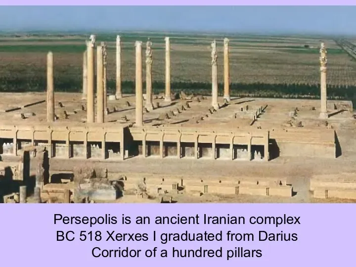
Persepolis is an ancient Iranian complex
BC 518 Xerxes I graduated from
Persepolis is an ancient Iranian complex
BC 518 Xerxes I graduated from
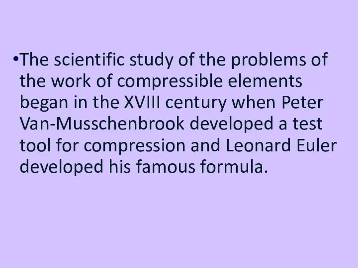
The scientific study of the problems of the work of compressible
The scientific study of the problems of the work of compressible
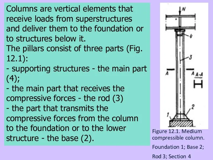
Figure 12.1. Medium compressible column.
Foundation 1; Base 2;
Rod 3; Section 4
Columns
Figure 12.1. Medium compressible column.
Foundation 1; Base 2;
Rod 3; Section 4
Columns
1 - rod;
2 - the main part;
3 - console;
4 - base
Types
1 - rod;
2 - the main part;
3 - console;
4 - base
Types
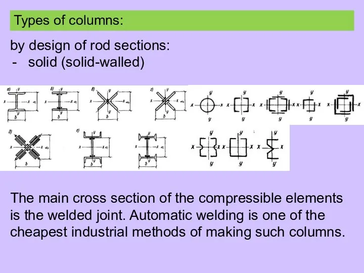
by design of rod sections:
solid (solid-walled)
The main cross section of the
by design of rod sections:
solid (solid-walled)
The main cross section of the
by design of rod sections:
- transitional (lattice)
Types of columns:
by design of rod sections:
- transitional (lattice)
Types of columns:
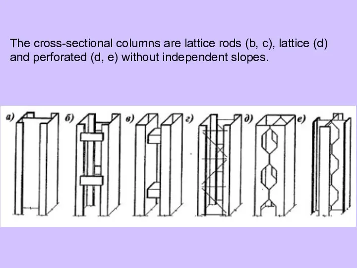
The cross-sectional columns are lattice rods (b, c), lattice (d) and
The cross-sectional columns are lattice rods (b, c), lattice (d) and
The maximum design load of a transition beam with a cross
The maximum design load of a transition beam with a cross
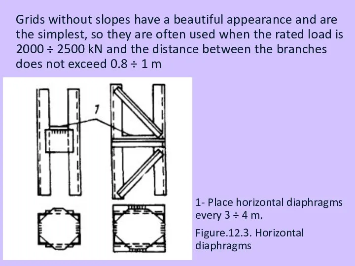
Grids without slopes have a beautiful appearance and are the simplest,
Grids without slopes have a beautiful appearance and are the simplest,
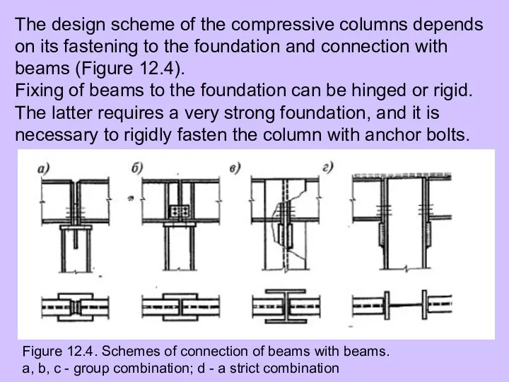
The design scheme of the compressive columns depends on its fastening
The design scheme of the compressive columns depends on its fastening
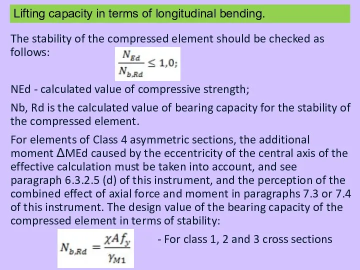
The stability of the compressed element should be checked as follows:
NEd
The stability of the compressed element should be checked as follows:
NEd
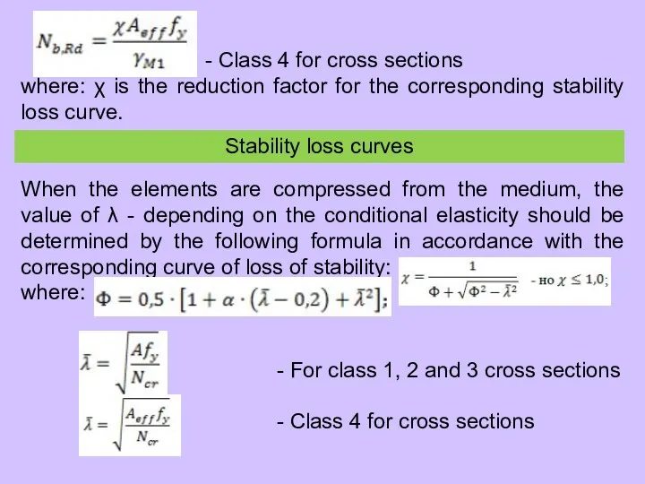
- Class 4 for cross sections
where: χ is the reduction
- Class 4 for cross sections
where: χ is the reduction
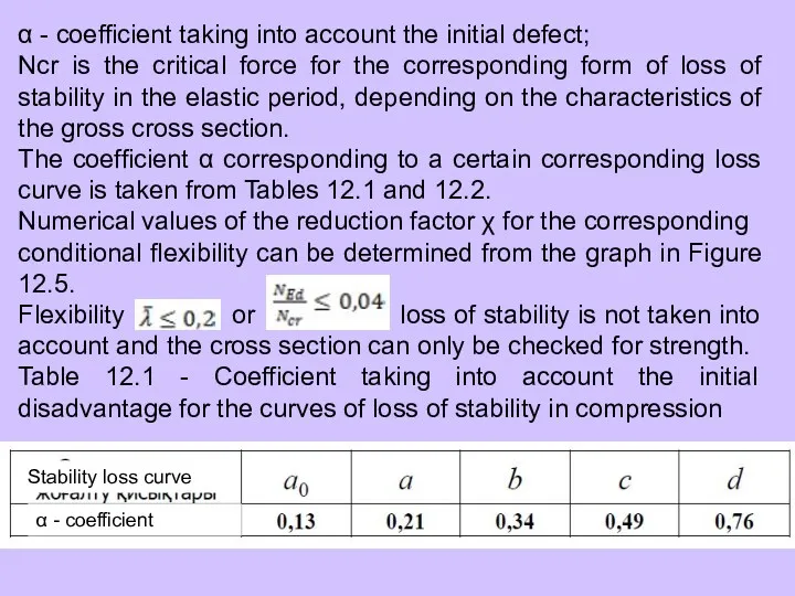
α - coefficient taking into account the initial defect;
Ncr is the
α - coefficient taking into account the initial defect;
Ncr is the
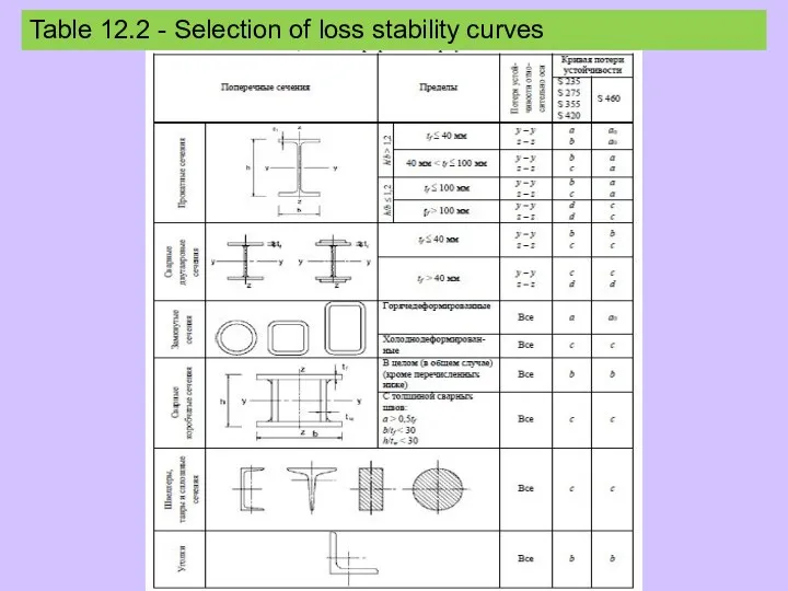
Table 12.2 - Selection of loss stability curves
Table 12.2 - Selection of loss stability curves
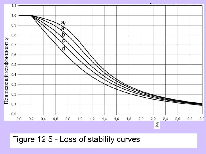
Figure 12.5 - Loss of stability curves
Figure 12.5 - Loss of stability curves
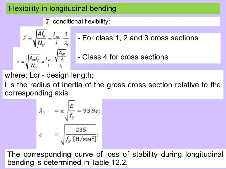
conditional flexibility:
Flexibility in longitudinal bending
- For class 1, 2 and 3
conditional flexibility:
Flexibility in longitudinal bending
- For class 1, 2 and 3
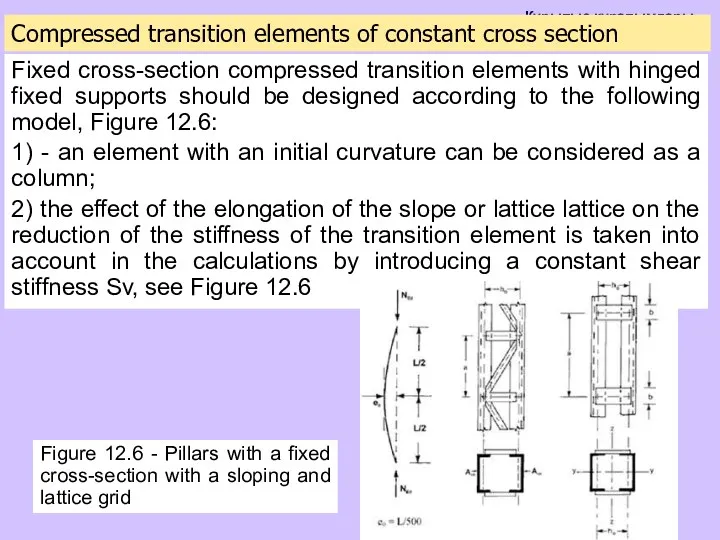
Compressed transition elements of constant cross section
Fixed cross-section compressed transition elements
Compressed transition elements of constant cross section
Fixed cross-section compressed transition elements
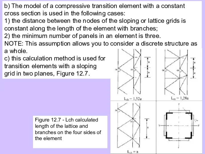
b) The model of a compressive transition element with a constant
b) The model of a compressive transition element with a constant
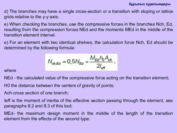
d) The branches may have a single cross-section or a transition
d) The branches may have a single cross-section or a transition
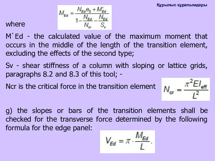
where
M`Ed - the calculated value of the maximum moment that occurs
where
M`Ed - the calculated value of the maximum moment that occurs
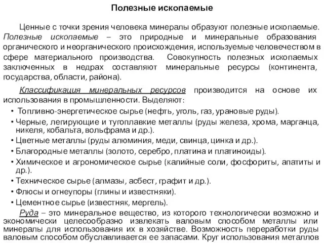 Полезные ископаемые
 Биологиялық мембрананың өткізгіштік механаимі. Иондық каналдар және тасымалдаушылардың құрылысы мен функциясы
 Основы православной культуры
 English-speaking countries. Викторина
 Реализация художественноэстетического направления развития детей дошкольного возраста в аспекте ФГОС ДО по программе Радуга
 Пилигримы в пути
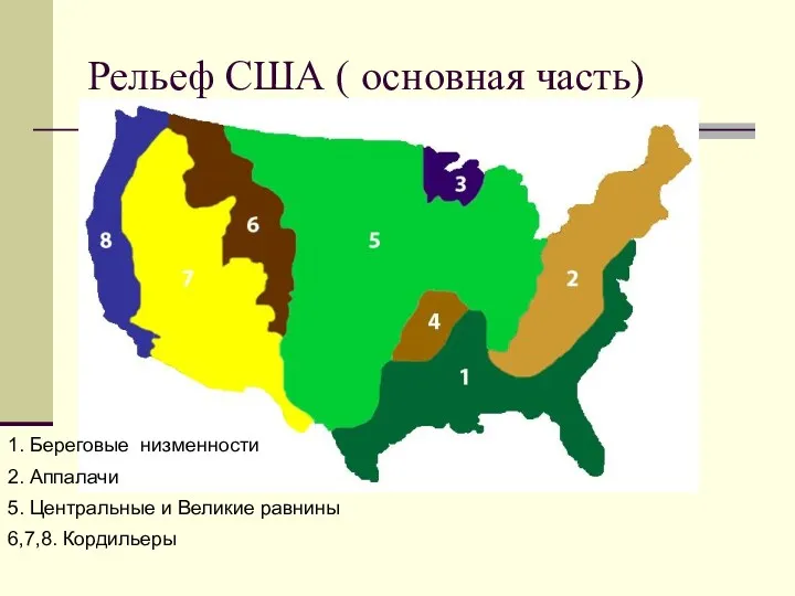 7 класс: Рельеф С.Америки
 Шумы и помехи
 Бүйрек, несепағар жарақаттары
 Монастыри, основанные Сергием Радонежским
 Кислородные соединения азота
 Презентация Развитие связной речи посредством театрализованной деятельности
 Лучевая диагностика выделительной системы
 Духовная зрелость человека
 Презентация Добрые дела на все времена
 презентация к уроку в 9 классе Тоталитарные режимы 1930-х годов: Италия, Германия, Испания
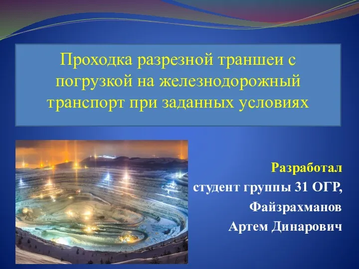 Проходка разрезной траншеи с погрузкой на железнодорожный транспорт при заданных условиях
 Здоровьесберегающие технологии в коррекционной работе с детьми
 Блокада Ленинграда
 Сенсоры. Классификация сенсоров. Миниатюрные электрорадиомеханические и оптоэлектромеханические компоненты
 Приобщение детей к национально-культурным традициям с помощью коллажей и мнемотаблиц
 Tiens-life. Ваше здоровье - в ваших руках!
 Контроль сварных стыков газопровода с методами неразрушающего контроля
 Объем прямоугольного параллелепипеда и треугольной призмы. Решение задач по готовым чертежам
 Собственный бизнес
 Классный час по теме Конституция РФ
 Презентация Мышление и его роль в профессиональном самоопределении личности
 Письменное деление многозначных чисел на трехзначное число