- Computer structure pipeline

Содержание
- 2. A Basic Processor Memory Write back Execute Decode Fetch PC Data Cache Register File Control signals
- 3. Pipelined Car Assembly chassis engine finish 1 hour 2 hours 1 hour Car 1 Car 2
- 4. Data Access Data Access Data Access Data Access Data Access Pipelining Instructions Ideal speedup is number
- 5. Pipelining Pipelining does not reduce the latency of single task, it increases the throughput of entire
- 6. Pipelined CPU dst
- 7. Structural Hazard Different instructions using the same resource at the same time Register File: Accessed in
- 8. Pipeline Example: cycle 1 0 lw R10,9(R1) 4 sub R11,R2,R3 8 and R12,R4,R5 12 or R13,R6,R7
- 9. Pipeline Example: cycle 2 0 lw R10,9(R1) 4 sub R11,R2,R3 8 and R12,R4,R5 12 or R13,R6,R7
- 10. Pipeline Example: cycle 3 0 lw R10,9(R1) 4 sub R11,R2,R3 8 and R12,R4,R5 12 or R13,R6,R7
- 11. Pipeline Example: cycle 4 0 lw R10,9(R1) 4 sub R11,R2,R3 8 and R12,R4,R5 12 or R13,R6,R7
- 12. Pipeline Example: cycle 5 0 lw R10,9(R1) 4 sub R11,R2,R3 8 and R12,R4,R5 12 or R13,R6,R7
- 13. RAW Dependency sub R2, R1, R3 and R12,R2, R5 or R13,R6, R2 add R14,R2, R2 sw
- 14. Using Bypass to Solve RAW Dependency sub R2, R1, R3 and R12,R2, R5 or R13,R6, R2
- 15. RAW Dependency 0 lw R4,9(R1) 4 sub R5,R2,R3 8 and R12,R4,R5 12 or R13,R6,R7 dst
- 16. Forwarding Hardware 0 lw R4,9(R1) 4 sub R5,R2,R3 8 and R12,R4,R5 12 or R13,R6,R7 dst
- 17. Forwarding Control Forwarding from EXE (L3) if (L3.RegWrite and (L3.dst == L2.src1)) ALUSelA = 1 if
- 18. Register File Split Register file is written during first half of the cycle Register file is
- 19. Load word can still causes a hazard: an instruction tries to read a register following a
- 20. De-assert the enable to the L1 latch, and to the IP The dependent instruction (and) stays
- 21. Example: code for (assume all variables are in memory): a = b + c; d =
- 22. Control Hazards
- 23. Control Hazard on Branches
- 24. Control Hazard on Branches
- 25. Control Hazard on Branches
- 26. Control Hazard on Branches
- 27. Control Hazard on Branches
- 28. Control Hazard on Branches And Beq sub mul The 3 instructions following the branch get into
- 29. Control Hazard: Stall Stall pipe when branch is encountered until resolved Stall impact: assumptions CPI =
- 30. Control Hazard: Predict Not Taken Execute instructions from the fall-through (not-taken) path As if there is
- 31. Dynamic Branch Prediction Add a Branch Target Buffer (BTB) that predicts (at fetch) Instruction is a
- 32. BTB Allocation Allocate instructions identified as branches (after decode) Both conditional and unconditional branches are allocated
- 33. BTB (cont.) Wrong prediction Predict not-taken, actual taken Predict taken, actual not-taken, or actual taken but
- 34. Adding a BTB to the Pipeline 4 50 50 Lookup current IP in IC and in
- 35. Adding a BTB to the Pipeline 50 taken 8 jcc sub 50 54 0 or 4
- 36. Adding a BTB to the Pipeline or jcc 50 taken 0 or 4 jcc 50 8
- 37. Using The BTB PC moves to next instruction Inst Mem gets PC and fetches new inst
- 38. Using The BTB (cont.) ID EXE MEM WB Calculate br cond & trgt Flush pipe &
- 39. Backup
- 40. R-type (register insts) I-type (Load, Store, Branch, inst’s w/imm data) J-type (Jump) op: operation of the
- 41. Each memory location is 8 bit = 1 byte wide has an address We assume 32
- 42. Register File The Register File holds 32 registers Each register is 32 bit wide The RF
- 43. Memory Components Inputs Address: address of the memory location we wish to access Read: read data
- 44. The Program Counter (PC) Holds the address (in memory) of the next instruction to be executed
- 45. Fetch Fetch instruction pointed by PC from I-Cache Decode Decode instruction (generate control signals) Fetch operands
- 46. The MIPS CPU Instruction Decode / register fetch Instruction fetch Execute / address calculation Memory access
- 47. Executing an Add Instruction R3 R5 3 5 R3 + R5 + [PC]+4 2 Add R2,
- 48. Executing a Load Instruction LW R1, (30)R2 ; R1 ← Mem[R2+30]
- 49. Executing a Store Instruction SW R1, (30)R2 ; Mem[R2+30] ← R1
- 50. Executing a BEQ Instruction BEQ R4, R5, 27 ; if (R4-R5=0) then PC ← PC+4+SignExt(27)*4 ;
- 51. Control Signals
- 52. Pipelined CPU: Load (cycle 1 – Fetch) lw op rs rt immediate 0 16 21 26
- 53. Pipelined CPU: Load (cycle 2 – Dec) op rs rt immediate 0 16 21 26 31
- 54. Pipelined CPU: Load (cycle 3 – Exe) op rs rt immediate 0 16 21 26 31
- 55. Pipelined CPU: Load (cycle 4 – Mem) op rs rt immediate 0 16 21 26 31
- 56. Pipelined CPU: Load (cycle 5 – WB) op rs rt immediate 0 16 21 26 31
- 57. Datapath with Control
- 58. Multi-Cycle Control Pass control signals along just like the data
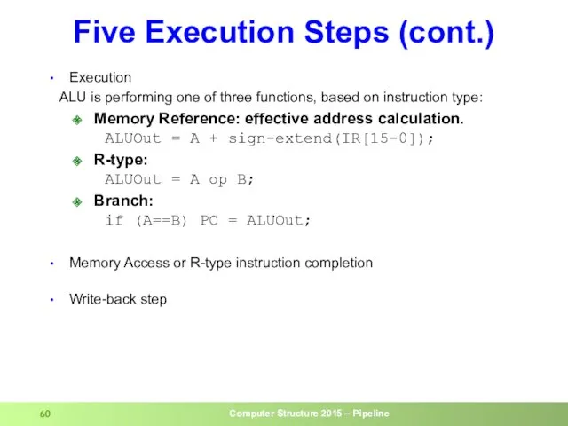
- 59. Five Execution Steps Instruction Fetch Use PC to get instruction and put it in the Instruction
- 60. Five Execution Steps (cont.) Execution ALU is performing one of three functions, based on instruction type:
- 61. The Store Instruction sw rt, rs, imm16 mem[PC] Fetch the instruction from memory Addr Calculate the
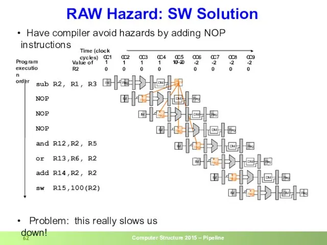
- 62. RAW Hazard: SW Solution I M R e g C C 1 C C 2 C
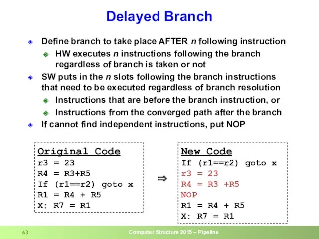
- 63. Delayed Branch Define branch to take place AFTER n following instruction HW executes n instructions following
- 65. Скачать презентацию
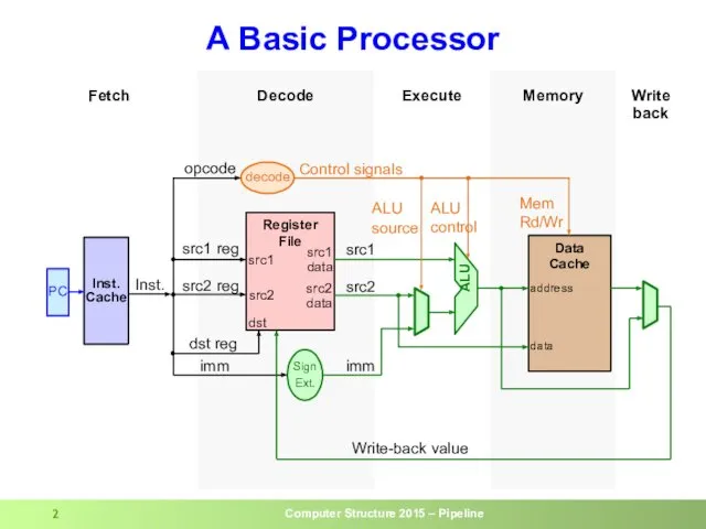
A Basic Processor
Memory
Write
back
Execute
Decode
Fetch
PC
Data
Cache
Register
File
Control signals
ALU
Inst.
src1
Inst.
Cache
address
Sign
Ext.
Mem
Rd/Wr
ALU control
decode
src1
data
src2
data
src2
dst
data
dst reg
ALU source
imm
src2
src1
Write-back value
imm
opcode
src1 reg
src2
A Basic Processor
Memory
Write
back
Execute
Decode
Fetch
PC
Data
Cache
Register
File
Control signals
ALU
Inst.
src1
Inst.
Cache
address
Sign
Ext.
Mem
Rd/Wr
ALU control
decode
src1
data
src2
data
src2
dst
data
dst reg
ALU source
imm
src2
src1
Write-back value
imm
opcode
src1 reg
src2
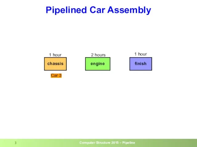
Pipelined Car Assembly
chassis
engine
finish
1 hour
2 hours
1 hour
Car 1
Car 2
Car 3
Pipelined Car Assembly
chassis
engine
finish
1 hour
2 hours
1 hour
Car 1
Car 2
Car 3
Data
Access
Data
Access
Data
Access
Data
Access
Data
Access
Pipelining Instructions
Ideal speedup is number of stages in the pipeline. Do
Data
Access
Data
Access
Data
Access
Data
Access
Data
Access
Pipelining Instructions
Ideal speedup is number of stages in the pipeline. Do
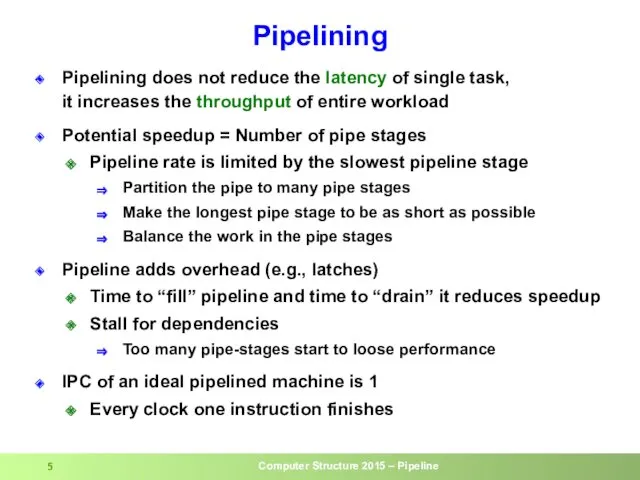
Pipelining
Pipelining does not reduce the latency of single task,
it increases
Pipelining
Pipelining does not reduce the latency of single task, it increases
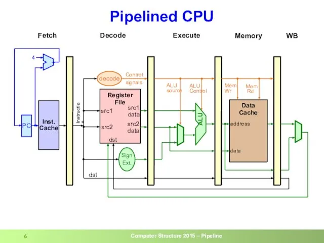
Pipelined CPU
dst
Pipelined CPU
dst
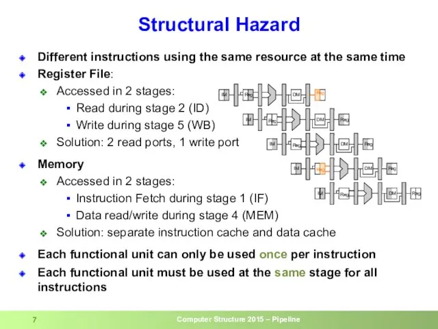
Structural Hazard
Different instructions using the same resource at the same time
Register
Structural Hazard
Different instructions using the same resource at the same time
Register

Pipeline Example: cycle 1
0 lw R10,9(R1)
4 sub R11,R2,R3
8
Pipeline Example: cycle 1
0 lw R10,9(R1)
4 sub R11,R2,R3
8

Pipeline Example: cycle 2
0 lw R10,9(R1)
4 sub R11,R2,R3
8
Pipeline Example: cycle 2
0 lw R10,9(R1)
4 sub R11,R2,R3
8

Pipeline Example: cycle 3
0 lw R10,9(R1)
4 sub R11,R2,R3
8
Pipeline Example: cycle 3
0 lw R10,9(R1)
4 sub R11,R2,R3
8
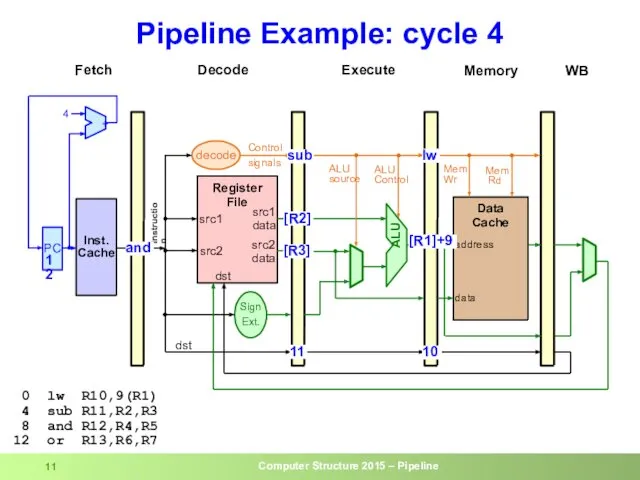
Pipeline Example: cycle 4
0 lw R10,9(R1)
4 sub R11,R2,R3
8
Pipeline Example: cycle 4
0 lw R10,9(R1)
4 sub R11,R2,R3
8
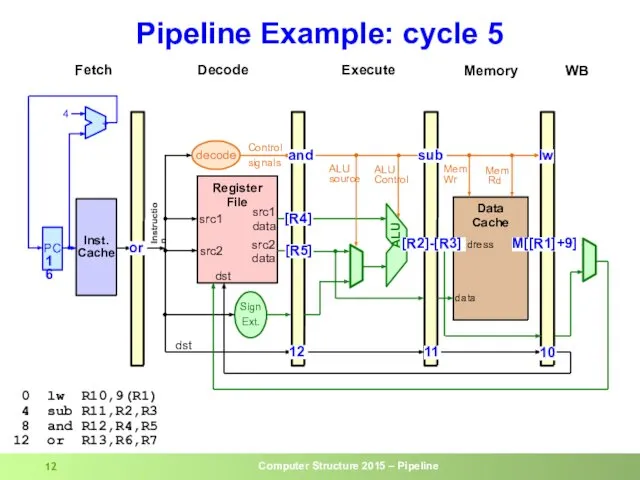
Pipeline Example: cycle 5
0 lw R10,9(R1)
4 sub R11,R2,R3
8
Pipeline Example: cycle 5
0 lw R10,9(R1)
4 sub R11,R2,R3
8
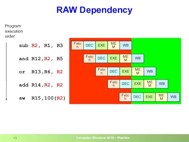
RAW Dependency
sub R2, R1, R3
and R12,R2, R5
or R13,R6, R2
add R14,R2, R2
sw
RAW Dependency
sub R2, R1, R3
and R12,R2, R5
or R13,R6, R2
add R14,R2, R2
sw
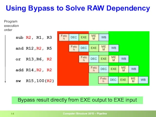
Using Bypass to Solve RAW Dependency
sub R2, R1, R3
and R12,R2, R5
or
Using Bypass to Solve RAW Dependency
sub R2, R1, R3
and R12,R2, R5
or
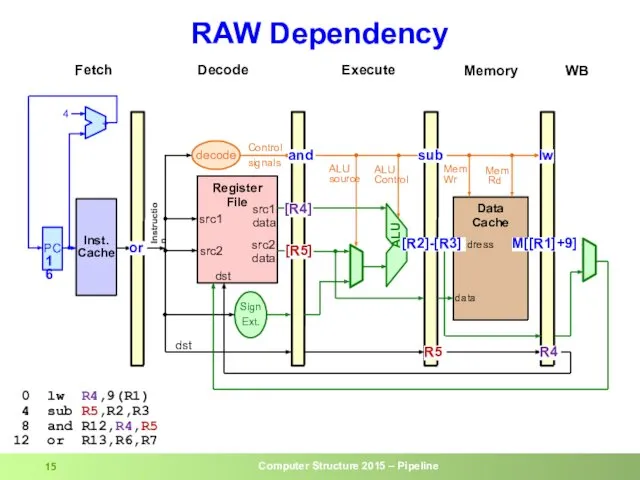
RAW Dependency
0 lw R4,9(R1)
4 sub R5,R2,R3
8 and R12,R4,R5
12
RAW Dependency
0 lw R4,9(R1)
4 sub R5,R2,R3
8 and R12,R4,R5
12
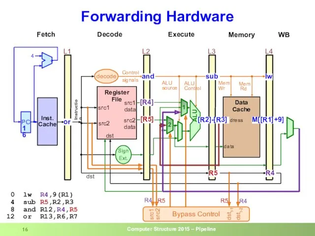
Forwarding Hardware
0 lw R4,9(R1)
4 sub R5,R2,R3
8 and R12,R4,R5
12
Forwarding Hardware
0 lw R4,9(R1)
4 sub R5,R2,R3
8 and R12,R4,R5
12
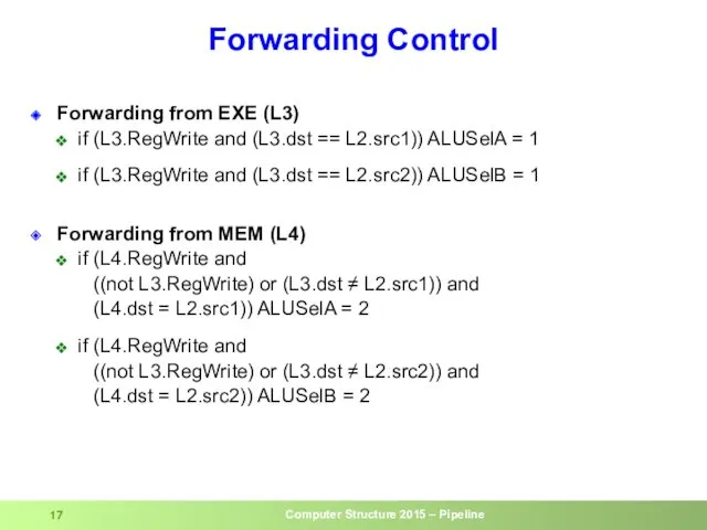
Forwarding Control
Forwarding from EXE (L3)
if (L3.RegWrite and (L3.dst == L2.src1))
Forwarding Control
Forwarding from EXE (L3)
if (L3.RegWrite and (L3.dst == L2.src1))
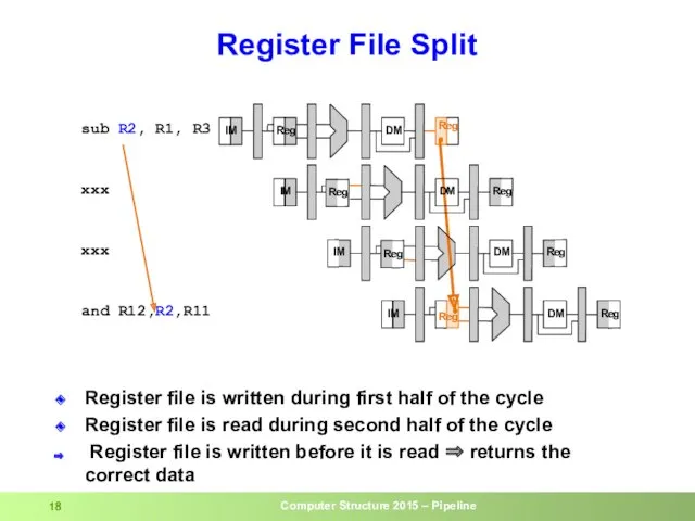
Register File Split
Register file is written during first half of the
Register File Split
Register file is written during first half of the
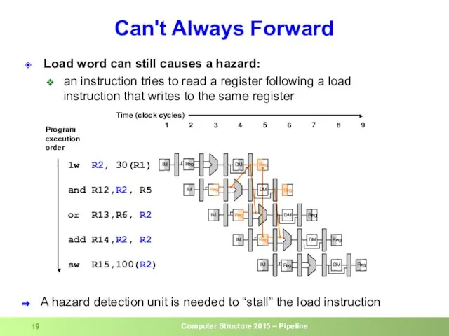
Load word can still causes a hazard:
an instruction tries to read
Load word can still causes a hazard:
an instruction tries to read
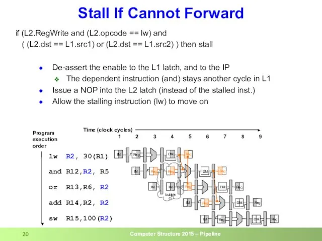
De-assert the enable to the L1 latch, and to the IP
The
De-assert the enable to the L1 latch, and to the IP
The
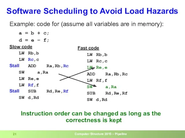
Example: code for (assume all variables are in memory):
a = b
Example: code for (assume all variables are in memory):
a = b
Control Hazards
Control Hazards
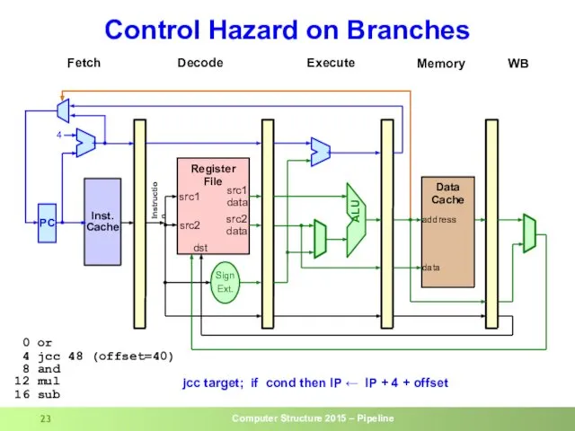
Control Hazard on Branches
Control Hazard on Branches

Control Hazard on Branches
Control Hazard on Branches

Control Hazard on Branches
Control Hazard on Branches
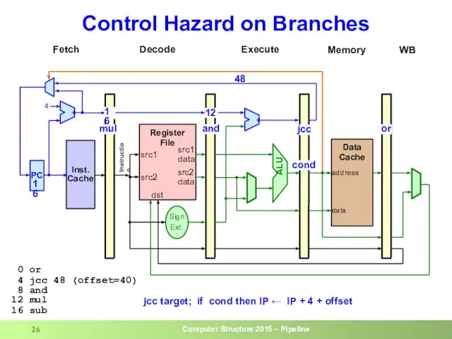
Control Hazard on Branches
Control Hazard on Branches
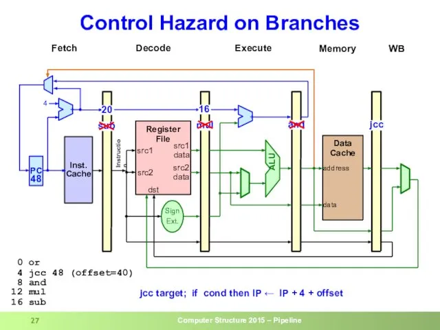
Control Hazard on Branches
Control Hazard on Branches
Control Hazard on Branches
And
Beq
sub
mul
The 3 instructions
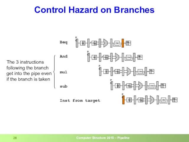
following the branch
get into
Control Hazard on Branches
And
Beq
sub
mul
The 3 instructions
following the branch
get into
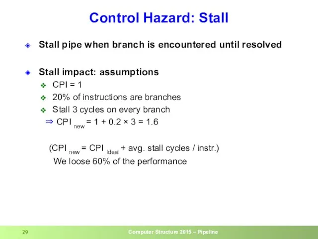
Control Hazard: Stall
Stall pipe when branch is encountered until resolved
Stall impact:
Control Hazard: Stall
Stall pipe when branch is encountered until resolved
Stall impact:
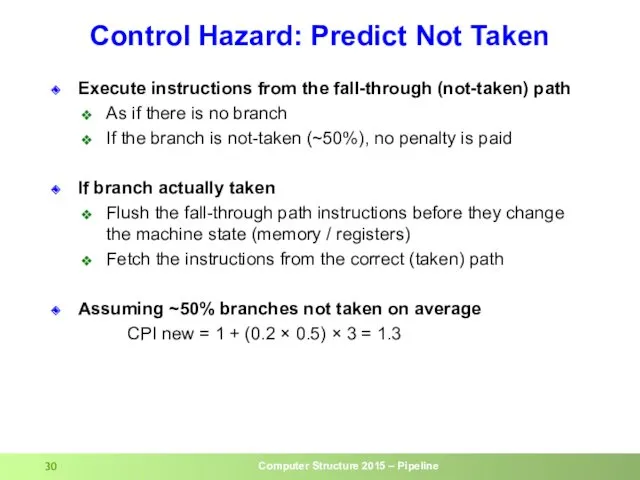
Control Hazard: Predict Not Taken
Execute instructions from the fall-through (not-taken) path
As
Control Hazard: Predict Not Taken
Execute instructions from the fall-through (not-taken) path
As
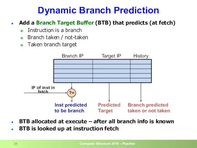
Dynamic Branch Prediction
Add a Branch Target Buffer (BTB) that predicts (at
Dynamic Branch Prediction
Add a Branch Target Buffer (BTB) that predicts (at
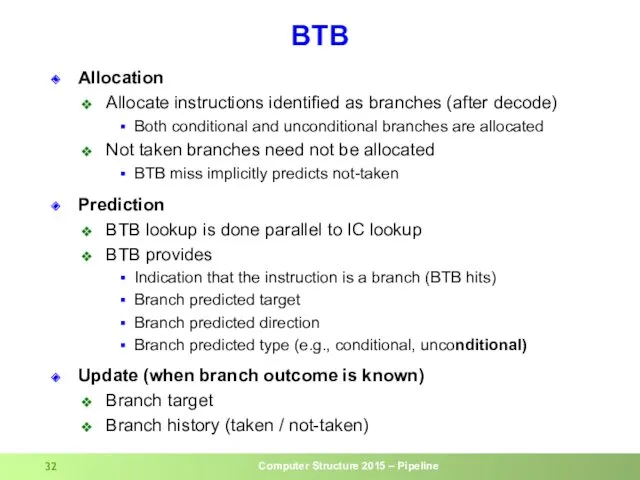
BTB
Allocation
Allocate instructions identified as branches (after decode)
Both conditional and unconditional branches
BTB
Allocation
Allocate instructions identified as branches (after decode)
Both conditional and unconditional branches
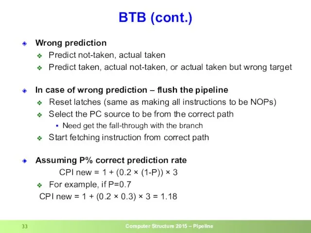
BTB (cont.)
Wrong prediction
Predict not-taken, actual taken
Predict taken, actual not-taken, or actual
BTB (cont.)
Wrong prediction
Predict not-taken, actual taken
Predict taken, actual not-taken, or actual
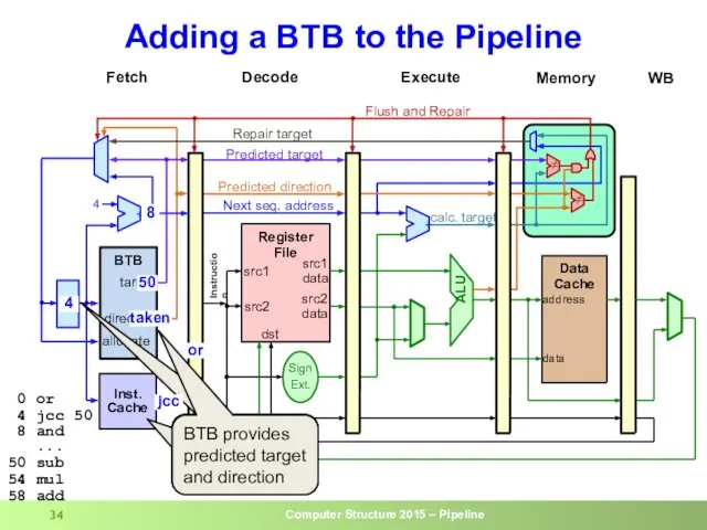
Adding a BTB to the Pipeline
4
50
50
Lookup current IP in IC and
Adding a BTB to the Pipeline
4
50
50
Lookup current IP in IC and
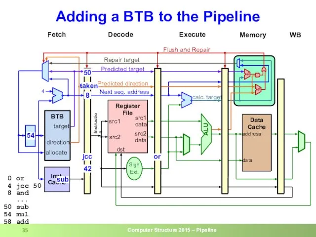
Adding a BTB to the Pipeline
50
taken
8
jcc
sub
50
54
0 or
4 jcc 50
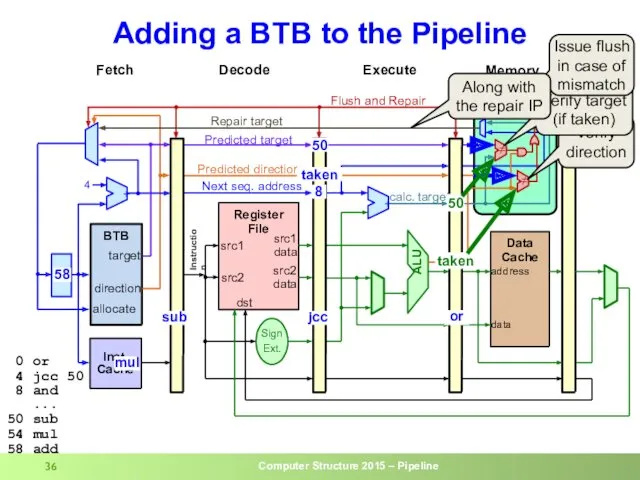
Adding a BTB to the Pipeline
50
taken
8
jcc
sub
50
54
0 or
4 jcc 50
Adding a BTB to the Pipeline
or
jcc
50
taken
0 or
4 jcc 50
Adding a BTB to the Pipeline
or
jcc
50
taken
0 or
4 jcc 50
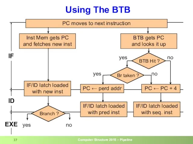
Using The BTB
PC moves to next instruction
Inst Mem gets PC
and fetches
Using The BTB
PC moves to next instruction
Inst Mem gets PC
and fetches
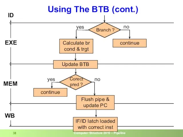
Using The BTB (cont.)
ID
EXE
MEM
WB
Calculate br
cond & trgt
Flush pipe &
update PC
yes
no
IF/ID latch
Using The BTB (cont.)
ID
EXE
MEM
WB
Calculate br
cond & trgt
Flush pipe &
update PC
yes
no
IF/ID latch
Backup
Backup
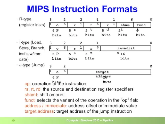
R-type
(register insts)
I-type (Load,
Store, Branch,
inst’s w/imm
data)
J-type
R-type
(register insts)
I-type (Load,
Store, Branch,
inst’s w/imm
data)
J-type
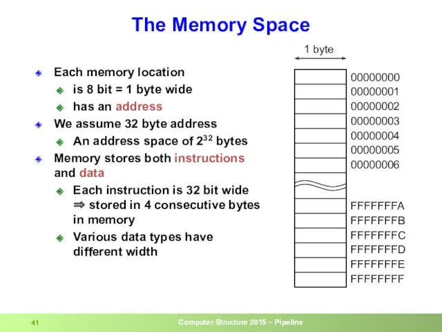
Each memory location
is 8 bit = 1 byte wide
has an
Each memory location
is 8 bit = 1 byte wide
has an
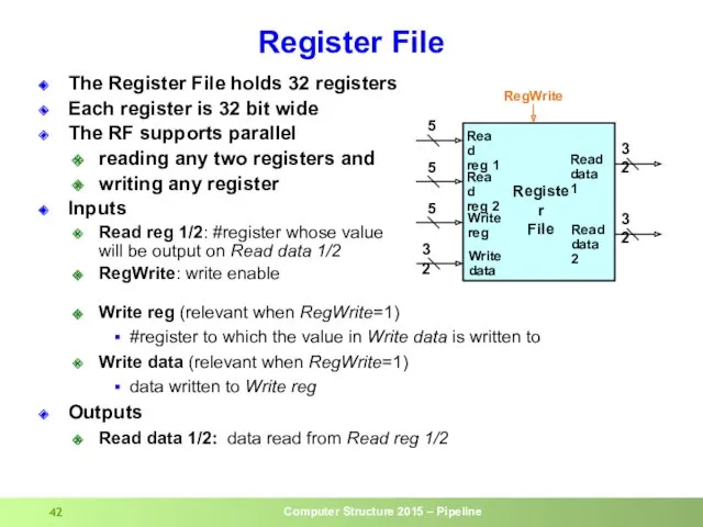
Register File
The Register File holds 32 registers
Each register is 32 bit
Register File
The Register File holds 32 registers
Each register is 32 bit
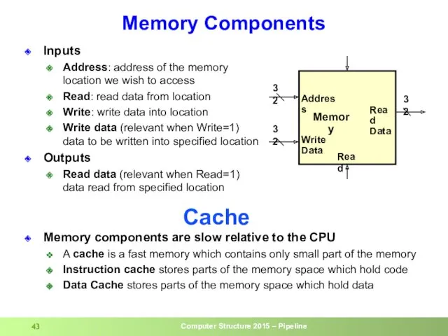
Memory Components
Inputs
Address: address of the memory location we wish to access
Read:
Memory Components
Inputs
Address: address of the memory location we wish to access
Read:
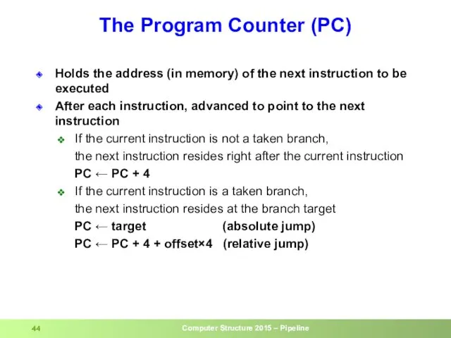
The Program Counter (PC)
Holds the address (in memory) of the next
The Program Counter (PC)
Holds the address (in memory) of the next
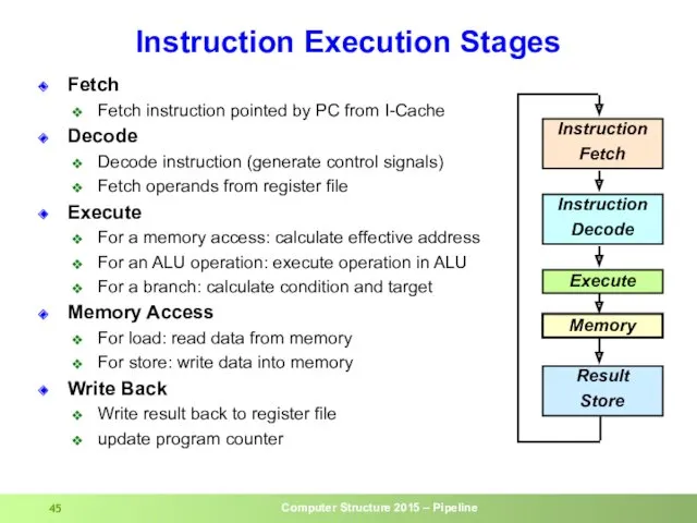
Fetch
Fetch instruction pointed by PC from I-Cache
Decode
Decode instruction (generate control signals)
Fetch
Fetch
Fetch instruction pointed by PC from I-Cache
Decode
Decode instruction (generate control signals)
Fetch
The MIPS CPU
Instruction
Decode /
register fetch
Instruction
fetch
Execute /
address
calculation
Memory
access
Write
back
The MIPS CPU
Instruction
Decode /
register fetch
Instruction
fetch
Execute /
address
calculation
Memory
access
Write
back
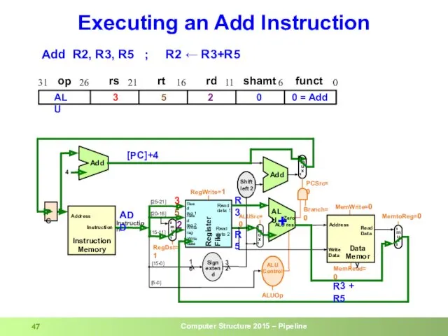
Executing an Add Instruction
R3
R5
3
5
R3 + R5
+
[PC]+4
2
Add R2, R3, R5 ; R2
Executing an Add Instruction
R3
R5
3
5
R3 + R5
+
[PC]+4
2
Add R2, R3, R5 ; R2
![Executing a Load Instruction LW R1, (30)R2 ; R1 ← Mem[R2+30]](/_ipx/f_webp&q_80&fit_contain&s_1440x1080/imagesDir/jpg/90721/slide-47.jpg)
Executing a Load Instruction
LW R1, (30)R2 ; R1 ← Mem[R2+30]
Executing a Load Instruction
LW R1, (30)R2 ; R1 ← Mem[R2+30]
![Executing a Store Instruction SW R1, (30)R2 ; Mem[R2+30] ← R1](/_ipx/f_webp&q_80&fit_contain&s_1440x1080/imagesDir/jpg/90721/slide-48.jpg)
Executing a Store Instruction
SW R1, (30)R2 ; Mem[R2+30] ← R1
Executing a Store Instruction
SW R1, (30)R2 ; Mem[R2+30] ← R1
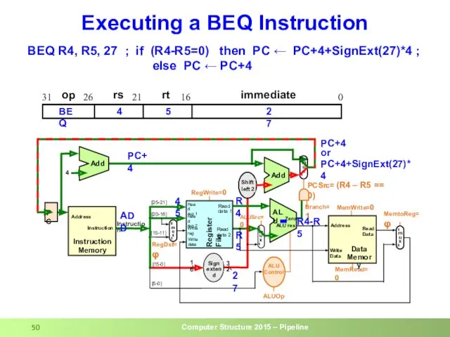
Executing a BEQ Instruction
BEQ R4, R5, 27 ; if (R4-R5=0) then
Executing a BEQ Instruction
BEQ R4, R5, 27 ; if (R4-R5=0) then
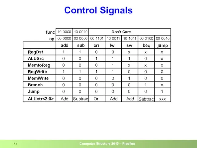
Control Signals
Control Signals

Pipelined CPU: Load (cycle 1 – Fetch)
lw
op
rs
rt
immediate
0
16
21
26
31
2
1
30
LW
LW R1, (30)R2 ; R1
Pipelined CPU: Load (cycle 1 – Fetch)
lw
op
rs
rt
immediate
0
16
21
26
31
2
1
30
LW
LW R1, (30)R2 ; R1
Pipelined CPU: Load (cycle 2 – Dec)
op
rs
rt
immediate
0
16
21
26
31
2
1
30
LW
LW R1, (30)R2 ; R1
Pipelined CPU: Load (cycle 2 – Dec)
op
rs
rt
immediate
0
16
21
26
31
2
1
30
LW
LW R1, (30)R2 ; R1

Pipelined CPU: Load (cycle 3 – Exe)
op
rs
rt
immediate
0
16
21
26
31
2
1
30
LW
LW R1, (30)R2 ; R1
Pipelined CPU: Load (cycle 3 – Exe)
op
rs
rt
immediate
0
16
21
26
31
2
1
30
LW
LW R1, (30)R2 ; R1

Pipelined CPU: Load (cycle 4 – Mem)
op
rs
rt
immediate
0
16
21
26
31
2
1
30
LW
LW R1, (30)R2 ; R1
Pipelined CPU: Load (cycle 4 – Mem)
op
rs
rt
immediate
0
16
21
26
31
2
1
30
LW
LW R1, (30)R2 ; R1
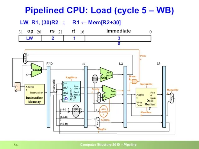
Pipelined CPU: Load (cycle 5 – WB)
op
rs
rt
immediate
0
16
21
26
31
2
1
30
LW
LW R1, (30)R2 ; R1
Pipelined CPU: Load (cycle 5 – WB)
op
rs
rt
immediate
0
16
21
26
31
2
1
30
LW
LW R1, (30)R2 ; R1
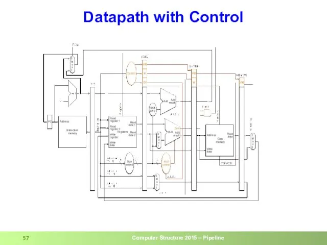
Datapath with Control
Datapath with Control
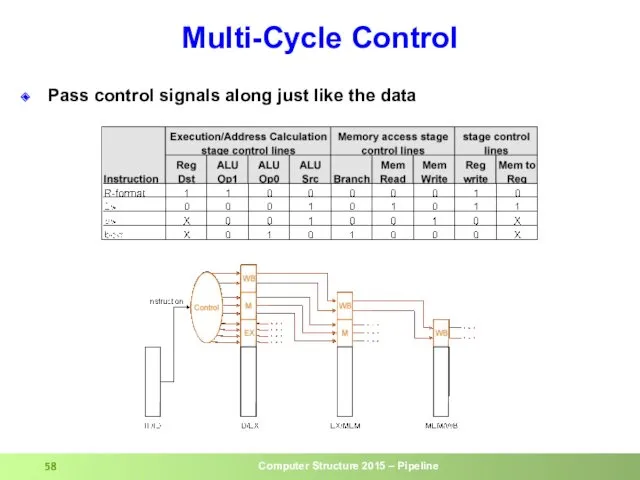
Multi-Cycle Control
Pass control signals along just like the data
Multi-Cycle Control
Pass control signals along just like the data
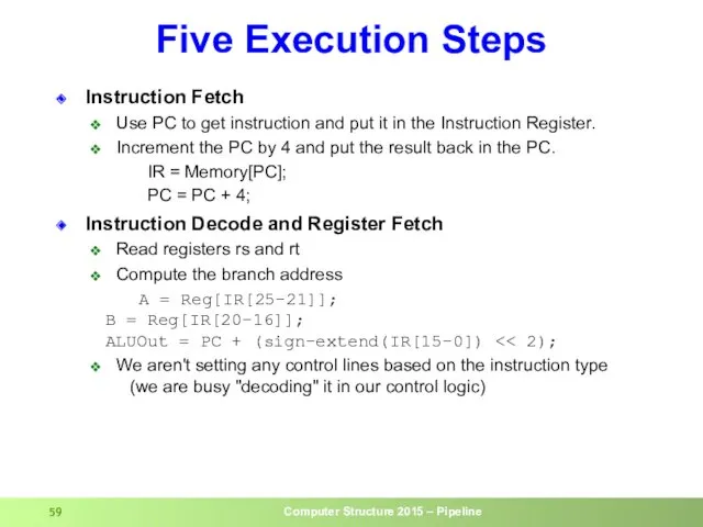
Five Execution Steps
Instruction Fetch
Use PC to get instruction and put it
Five Execution Steps
Instruction Fetch
Use PC to get instruction and put it
Five Execution Steps (cont.)
Execution
ALU is performing one of three functions,
Five Execution Steps (cont.)
Execution
ALU is performing one of three functions,
![The Store Instruction sw rt, rs, imm16 mem[PC] Fetch the](/_ipx/f_webp&q_80&fit_contain&s_1440x1080/imagesDir/jpg/90721/slide-60.jpg)
The Store Instruction
sw rt, rs, imm16
mem[PC] Fetch the instruction from memory
Addr <- R[rs]
The Store Instruction
sw rt, rs, imm16
mem[PC] Fetch the instruction from memory
Addr <- R[rs]
RAW Hazard: SW Solution
I
M
R
e
g
C
C
1
C
C
2
C
C
3
C
C
4
C
C
5
C
C
6
Time (clock
RAW Hazard: SW Solution
I
M
R
e
g
C
C
1
C
C
2
C
C
3
C
C
4
C
C
5
C
C
6
Time (clock
Delayed Branch
Define branch to take place AFTER n following instruction
HW executes
Delayed Branch
Define branch to take place AFTER n following instruction
HW executes
 Технология ремонта неисправностей и диагностика тостера
 Метапринципы развития высшего образования
 Декоративно-прикладное искусство
 Петр Великий
 Международные организации по стандартизации
 Основы общественного производства
 Специальная теория относительности. Относительность одновременности. Постулаты Эйнштейна
 будущим первоклассникам
 Посвящение в читатели
 Педагогическая практика. Курс Основы педагогической деятельности
 Правописание личных окончаний глаголов I и II спряжения
 День семьи
 Схемотехника телекоммуникационных устройств. Аналоговые электронные устройства
 „Nim cokolwiek powiesz, dwa razy przemyśl”. Rzecz o ósmym przykazaniu
 20-летие Конституции РФ
 Шрифты и особенность их применения в дизайне упаковки
 Консультация для воспитателей Использование приемов ТРИЗ-педагогики в развитие связной речи детей
 Дорожная одежда. Искусственные сооружения на автомобильных дорогах
 Самолёт АН-225 Мрия
 Использование информационных компьюторных технологий в обучении географии.
 Твердая фаза и поровое пространство почв. Плотность почвы
 Признаки равенства треугольников
 Технологическая карта визуального и измерительного метода контроля сварного соединения
 Java File IO. (Lesson 10)
 Общие и методические принципы физической культуры
 Кеңестік тоталитарлық Қазақстанның қалыптасуы: сипаты, шаралары, сабақтары
 Поэт, переводчик, писатель Борис Владимирович Заходер
 Презентация по производственной практике. Рекламное предприятие ГК Хром Дизайн