- Control valves

Содержание
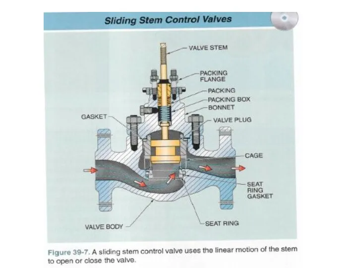
- 4. Sliding Stem Control Valves
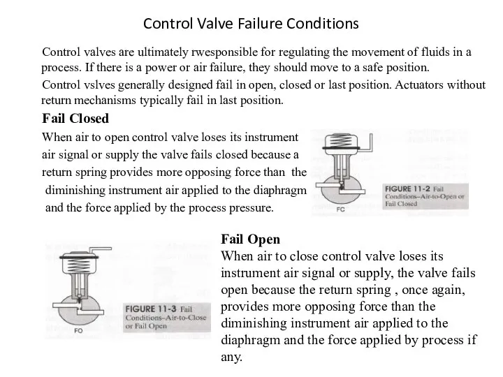
- 6. Control Valve Failure Conditions Control valves are ultimately rwesponsible for regulating the movement of fluids in
- 7. Fail in Place or Fail Last Pneumatic actuators with opposing springs naturally fail in the direction
- 8. Direct and reverse action A valve is considered to be direct acting when the valve stem
- 9. Pneumatically Drives Actuators There are two major subcategories of pneumatically drives actuators: the spring and diaprhagm
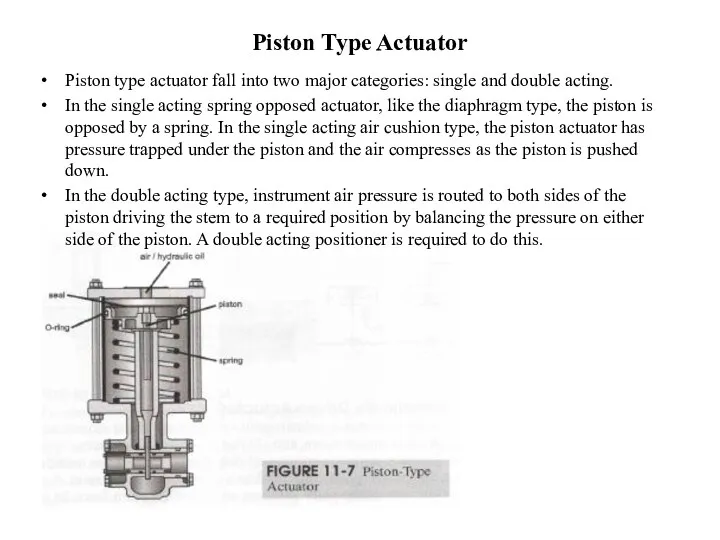
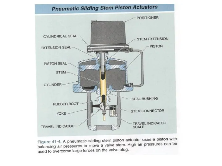
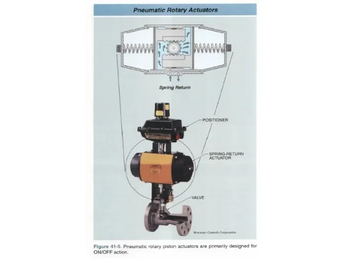
- 10. Piston Type Actuator Piston type actuator fall into two major categories: single and double acting. In
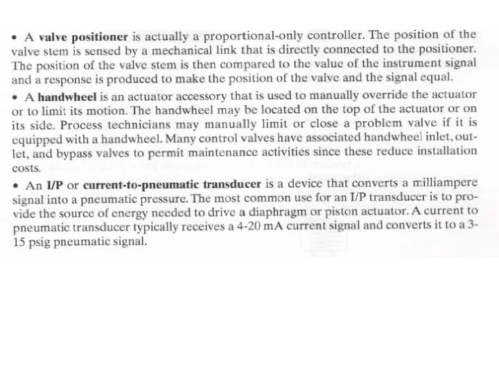
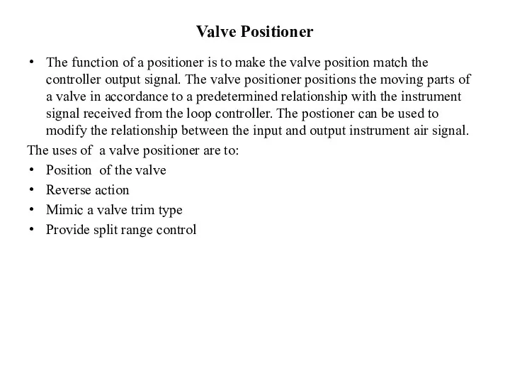
- 13. Valve Positioner The function of a positioner is to make the valve position match the controller
- 14. A valve positoner may be used to adjust the position of the valve according to specific
- 15. The controller output action, direct or reverse, is determined by what is necessary for proper feedback
- 16. A valve positioner may also be selected to mimic the characteristics of different valve trim types
- 17. Types of control valves The following are the main types of valves used in control confihurations:
- 18. A single port globe valve is a globe that consists of single valve plug and seat
- 19. In a double port valve, there is a division of the flow through the two ports.
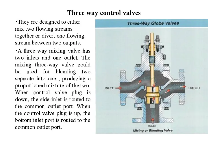
- 20. Three way control valves They are designed to either mix two flowing streams together or divert
- 21. A divertin valve is a three way valve that has one inlet and two outlets. The
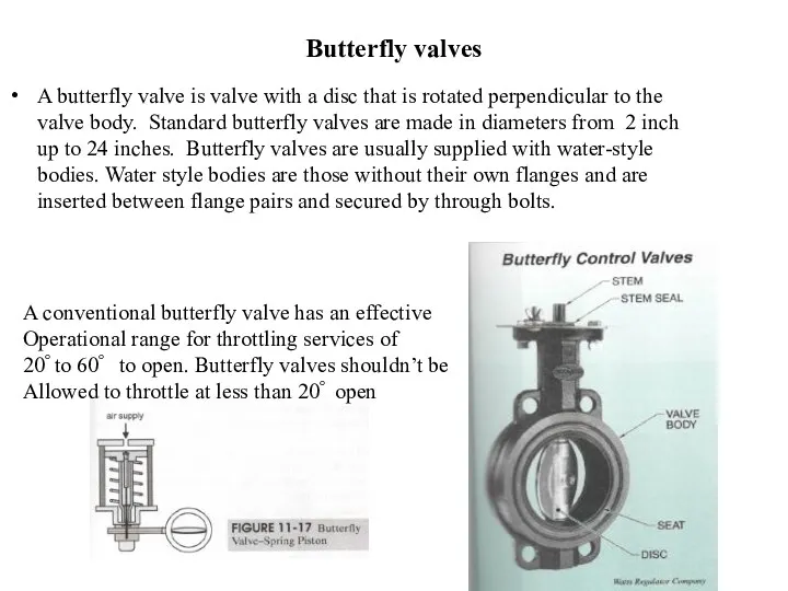
- 22. Butterfly valves A butterfly valve is valve with a disc that is rotated perpendicular to the
- 24. Скачать презентацию
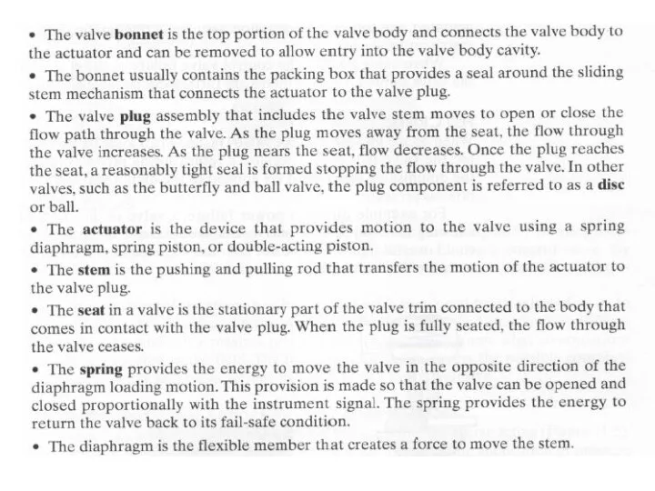
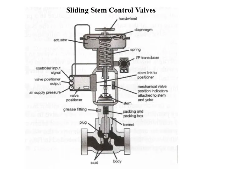
Sliding Stem Control Valves
Sliding Stem Control Valves
Control Valve Failure Conditions
Control valves are ultimately rwesponsible for regulating
Control Valve Failure Conditions
Control valves are ultimately rwesponsible for regulating
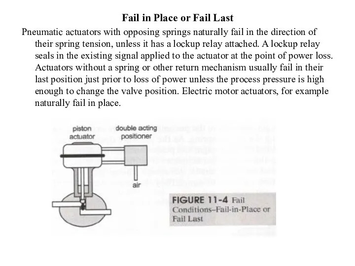
Fail in Place or Fail Last
Pneumatic actuators with opposing springs naturally
Fail in Place or Fail Last
Pneumatic actuators with opposing springs naturally
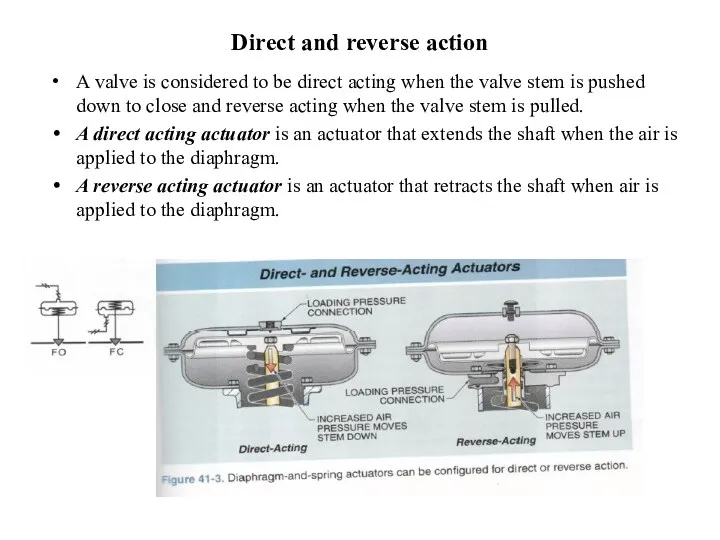
Direct and reverse action
A valve is considered to be direct acting
Direct and reverse action
A valve is considered to be direct acting
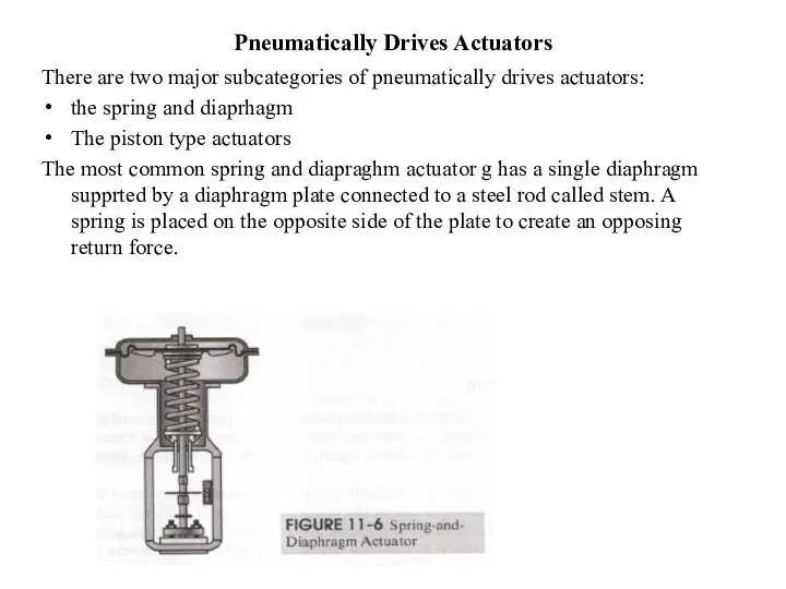
Pneumatically Drives Actuators
There are two major subcategories of pneumatically drives actuators:
Pneumatically Drives Actuators
There are two major subcategories of pneumatically drives actuators:
Piston Type Actuator
Piston type actuator fall into two major categories: single
Piston Type Actuator
Piston type actuator fall into two major categories: single
Valve Positioner
The function of a positioner is to make the valve
Valve Positioner
The function of a positioner is to make the valve
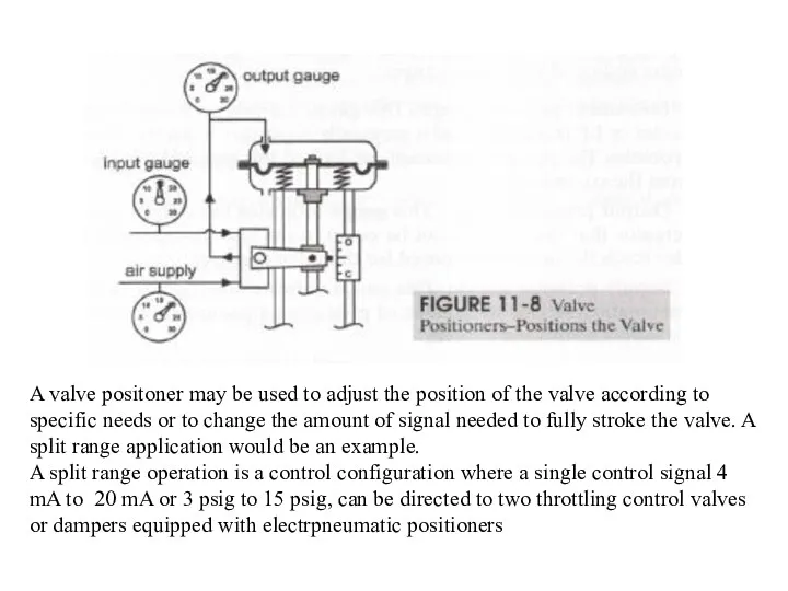
A valve positoner may be used to adjust the position of
A valve positoner may be used to adjust the position of
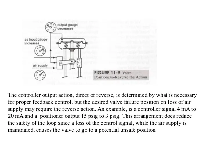
The controller output action, direct or reverse, is determined by what
The controller output action, direct or reverse, is determined by what

A valve positioner may also be selected to mimic the characteristics
A valve positioner may also be selected to mimic the characteristics
Types of control valves
The following are the main types of valves
Types of control valves
The following are the main types of valves
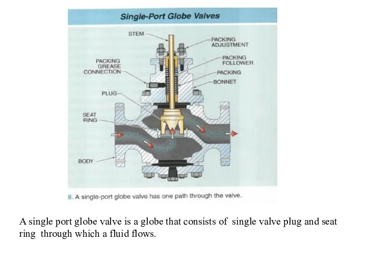
A single port globe valve is a globe that consists of
A single port globe valve is a globe that consists of
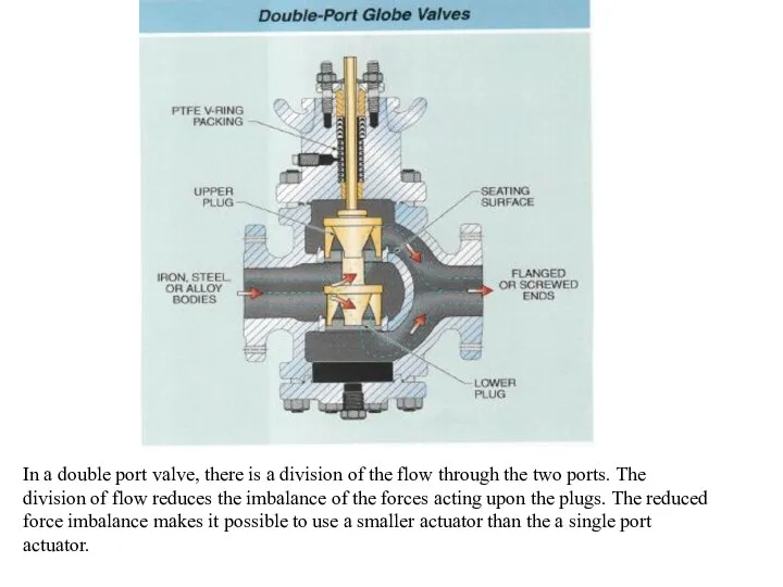
In a double port valve, there is a division of the
In a double port valve, there is a division of the
Three way control valves
They are designed to either mix two flowing
Three way control valves
They are designed to either mix two flowing
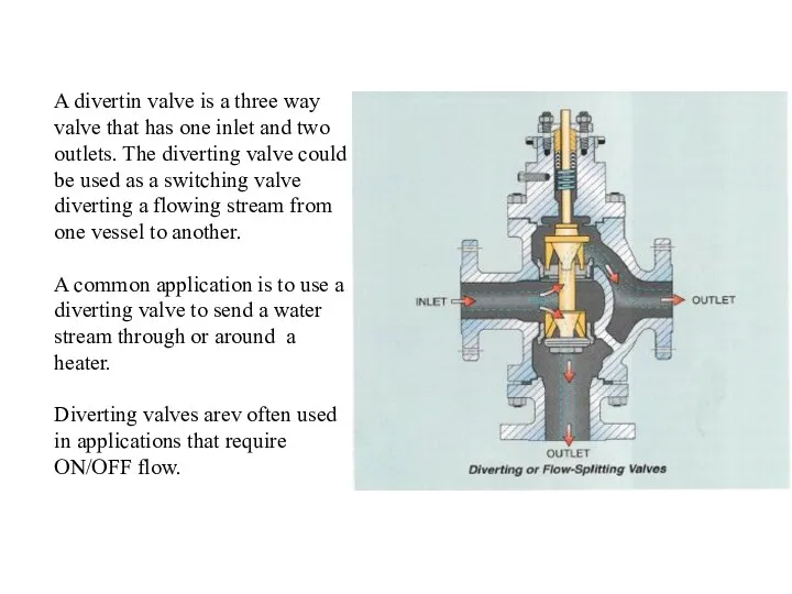
A divertin valve is a three way valve that has one
A divertin valve is a three way valve that has one
Butterfly valves
A butterfly valve is valve with a disc that is
Butterfly valves
A butterfly valve is valve with a disc that is
 Pierwsza Komunia
 Подготовка к тесту РСО. Тема 3: Кодекс
 Акция 7+1 Петровская Слобода
 The Adjective
 Презентация .Родительское собраниеРоль книги в жизни младших школьников
 Elementary interactions: hydrophobic & electrostatic; SS and coordinate bonds
 Быть разработчиком: вызовы, ожидания, перестроение мозгов
 Внеклассное мероприятие по Чеченской войне
 Марк Матвеевич Антокольский (1843 - 1902)
 Самые известные православные храмы России
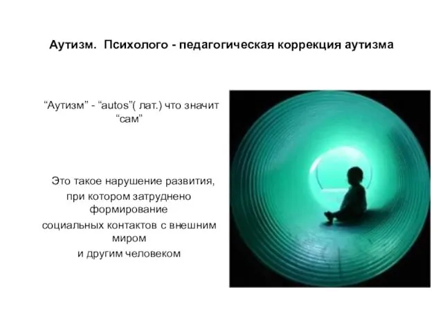 Аутизм. Психолого - педагогическая коррекция аутизма
 Балочная плита перекрытия, многопролетная неразрезная балка. Расчетная схема
 Социальная психология личности
 Проект по теме:Трудовая деятельность детей младшего школьного возраста
 Производство халвы
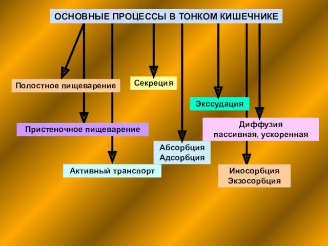 Основные процессы в тонком кишечнике
 Бароко
 Структуры осадочных пород
 Пациентке бағыттылған оқыту
 космос
 Ауа тамшы инфекциялары
 Тема 1.2. Основные этапы развития социологии
 Рельеф и полезные ископаемые Африки
 Различение звуков Ы-И.
 Государственный академический хореографический ансамбль Берёзка
 физминутка для малышей Ножки и ладошки
 Смотр достижения знаний в 4 классе Брейн-ринг.
 Символ коня в городецкой росписи