- Current and voltage transformers

Содержание
- 2. Измерительные трансформаторы тока и напряжения применяют в качестве преобразователей больших переменных токов и напряжений в относительно
- 3. secondary windings are rated for 5 A and 1A Also 2, 2.5, 10, 20 A CT
- 4. the leakage impedance of the primary winding Zx1 has no effect on the performance of the
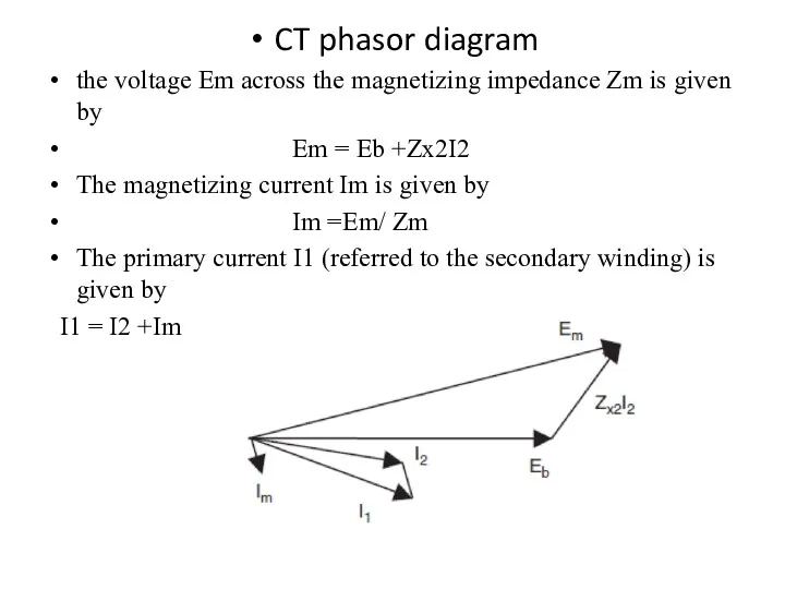
- 5. CT phasor diagram the voltage Em across the magnetizing impedance Zm is given by Em =
- 6. The per unit current transformation error defined by The ratio correction factor R is defined as
- 7. Example Consider a current transformer with a turns ratio of 500 : 5, a secondary leakage
- 8. Since the magnetizing branch of a practical transformer is nonlinear, Zm is not constant, and the
- 9. The magnetizing characteristic of a typical CT is shown in this Figure This being a plot
- 10. Из анализа полученных уравнений можно сделать следующие выводы: При возрастании сопротивления вторичной обмотки или ее разрыве
- 11. Polarity markings on CT windings Example Consider the CTs shown in Figures (a) and (b) If
- 12. Wye and delta connections In three-phase circuits, it is often necessary to connect the CT secondaries
- 13. Consider the CT connections shown in Figure The wye connection shown in Figure (a) produces currents
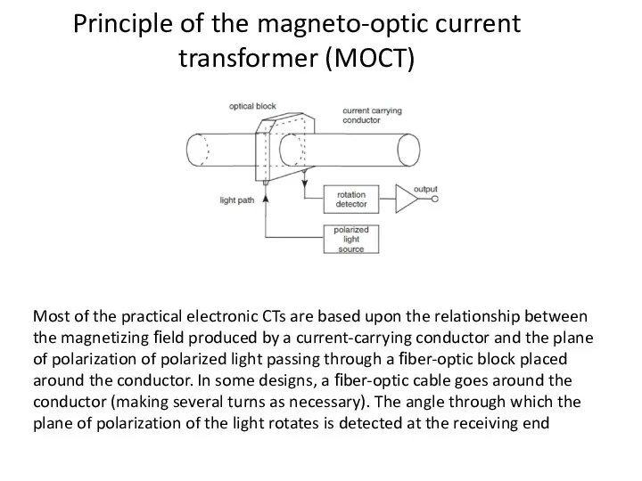
- 14. Principle of the magneto-optic current transformer (MOCT) Most of the practical electronic CTs are based upon
- 15. This angular shift is electronically converted to a voltage, which is proportional to the instantaneous value
- 16. Voltage transformers Voltage transformers – also known as potential transformers – are normal transformers with the
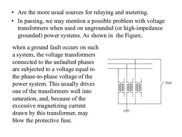
- 17. Are the more usual sources for relaying and metering. In passing, we may mention a possible
- 18. Coupling capacitor voltage transformers CCVT Connections and equivalent circuit
- 20. Скачать презентацию
Измерительные трансформаторы тока и напряжения применяют в качестве преобразователей больших
Измерительные трансформаторы тока и напряжения применяют в качестве преобразователей больших
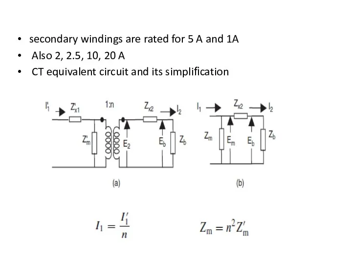
secondary windings are rated for 5 A and 1A
Also 2,
Also 2,
the leakage impedance of the primary winding Zx1 has no effect
the leakage impedance of the primary winding Zx1 has no effect
CT phasor diagram
the voltage Em across the magnetizing impedance Zm is
CT phasor diagram
the voltage Em across the magnetizing impedance Zm is
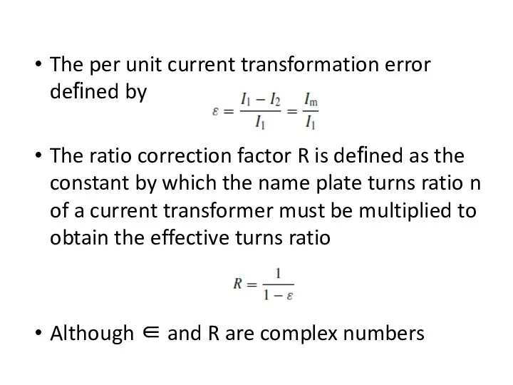
The per unit current transformation error defined by
The ratio correction factor
The per unit current transformation error defined by
The ratio correction factor
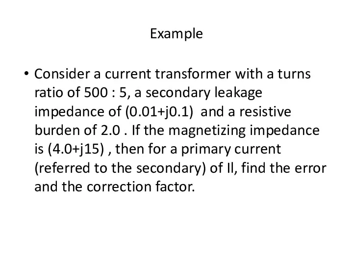
Example
Consider a current transformer with a turns ratio of 500 :
Example
Consider a current transformer with a turns ratio of 500 :
Since the magnetizing branch of a practical transformer is nonlinear, Zm
Since the magnetizing branch of a practical transformer is nonlinear, Zm
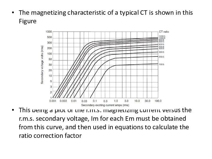
The magnetizing characteristic of a typical CT is shown in this
The magnetizing characteristic of a typical CT is shown in this
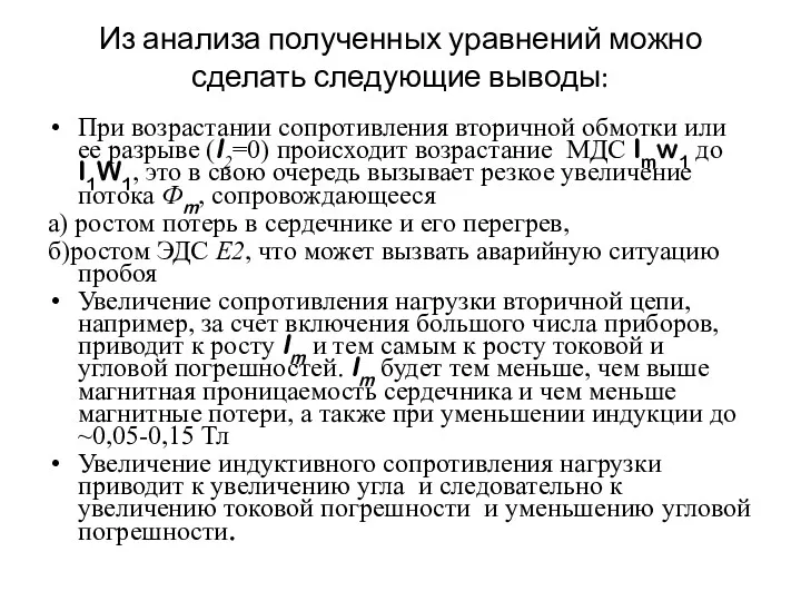
Из анализа полученных уравнений можно сделать следующие выводы:
При возрастании сопротивления вторичной
Из анализа полученных уравнений можно сделать следующие выводы:
При возрастании сопротивления вторичной
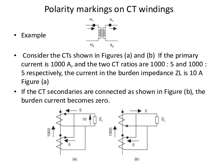
Polarity markings on CT windings
Example
Consider the CTs shown in
Polarity markings on CT windings
Example
Consider the CTs shown in
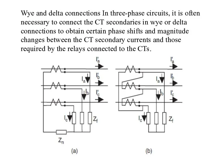
Wye and delta connections In three-phase circuits, it is often necessary
Wye and delta connections In three-phase circuits, it is often necessary
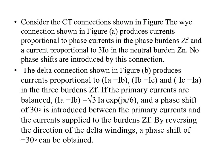
Consider the CT connections shown in Figure The wye connection shown
Consider the CT connections shown in Figure The wye connection shown
Principle of the magneto-optic current transformer (MOCT)
Most of the practical electronic
Principle of the magneto-optic current transformer (MOCT)
Most of the practical electronic
This angular shift is electronically converted to a voltage, which is
This angular shift is electronically converted to a voltage, which is
Voltage transformers
Voltage transformers – also known as potential transformers – are
Voltage transformers
Voltage transformers – also known as potential transformers – are
Are the more usual sources for relaying and metering.
In passing,
Are the more usual sources for relaying and metering.
In passing,
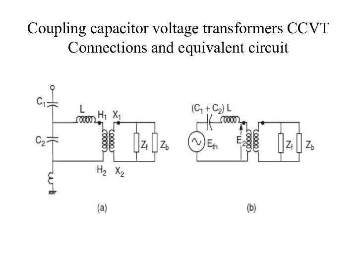
Coupling capacitor voltage transformers CCVT Connections and equivalent circuit
Coupling capacitor voltage transformers CCVT Connections and equivalent circuit
 Имена героев в названиях улиц города Советска
 Навесное оборудование для малогабиритной тяговой установки
 Сварочные выпрямители
 Аналитический обзор современных швейных машин потайного стежка
 Удостоверение сделок. Доверенность. Завещание и его формы
 Устройство карпового прудового рыбхоза
 Класс Пресмыкающиеся
 Парк флоры и фауны Роев ручей
 Поздравляем с Днём МАМ!
 Конкурс рисунков
 Призентация к общешкольному мероприятию 9 Мая- День Победы
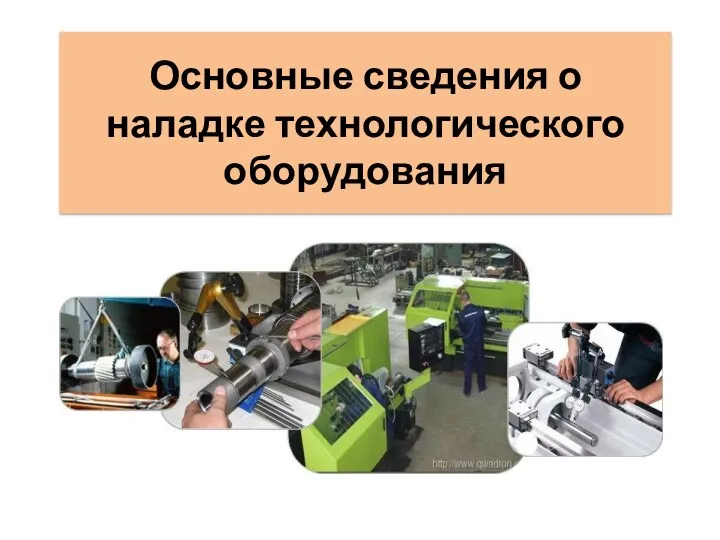 Наладка технологического оборудования на производстве
 Желаемые объекты Чкаловского парка
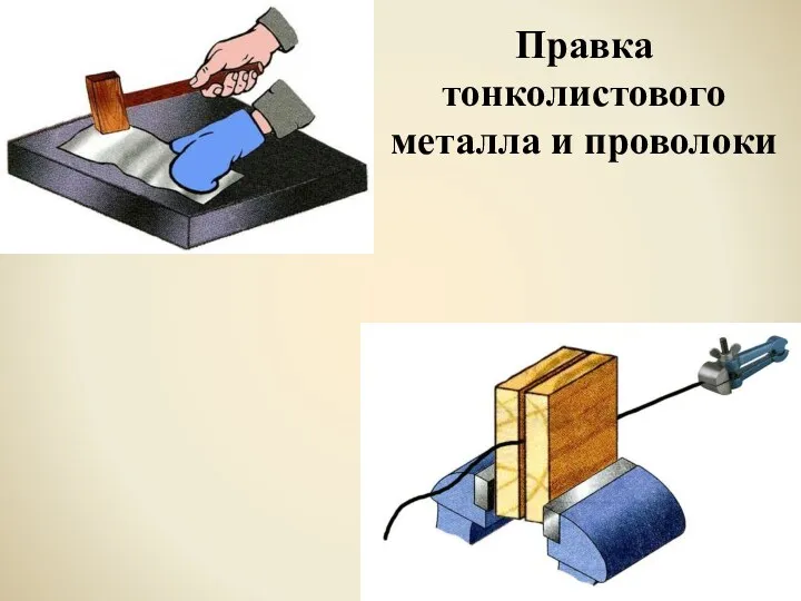 Правка тонколистового металла и проволоки. Проверь свои знания
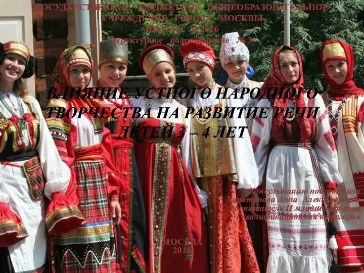 ВЛИЯНИЕ УСТНОГО НАРОДНОГО ТВОРЧЕСТВА НА РАЗВИТИЕ РЕЧИ ДЕТЕЙ 3 – 4 ЛЕТ.
 Логопедическое занятие для учащихся 3 класса (развитие связной речи) . Тема Плохо (по В. Осеевой)
 Блокада Ленинграда
 Проблемы корейского общества сквозь призму современной художественной литературы
 Презентация Православие и язычество на Руси.
 Презентация Нижний Новгород
 презентация Посуда
 Презентация кружка Волшебные краски часть 1
 Эмбриогенез человека
 Смутное время
 Реализация комплекса ГТО на территории Семикаракорского района
 Криминалистика как юридическая дисциплина
 Розвиток мовлення 4 клас ІІ семестр
 Международные отношения, мировая политика, внешняя политика и дипломатия в контексте новой научной парадигмы