- DATC -Dual Automatic Temperature Control -

Содержание
- 2. General Specification
- 3. Construction
- 4. Components HVAC (Heating Ventilation Air Conditioning)
- 5. Components Blower assembly Interior/Exterior air actuator Cluster ionizer Cation generation part Anion generation part ※ Cluster
- 6. Inputs & Outputs Tail lamp, Rheostat Dial switch (driver&pass temperature) Power (B+, IG2) and Ground DATC
- 7. Inputs & Outputs Tail lamp, Rheostat Dial switch (driver&pass temperature) Power (B+, IG2) and Ground DATC
- 8. Cluster ionizer Cluster ionizer Cation generation Anion generation
- 9. Cluster ionizer Cluster ionizer mode CLEAN mode : CLEAN display ION mode : ION display Cluster
- 10. With Mechanical Control Valve (DV) Control Valve (Mechanical Type) Magnetic Clutch Pulley (Steel) With Electric Control
- 11. With Mechanical Control Valve (VS) Control Valve (Mechanical Type) Magnetic Clutch Pulley (Steel) With Electric Control
- 12. A/C OFF Mode Control A/C ON & Variable Control Control room (Pressure Up) Suction room Exhaust
- 13. Control Block Diagram ECV (Electric Control Valve) In-car Temp. Sensor Ambient Temp. Photo Sensor Humidity Sensor
- 14. Owner’s setting procedure Defrost logic setting Temperature unit conversion 1. OFF button + AUTO button (5sec)
- 15. Owner’s setting procedure Self diagnosis (Using the control panel) Push MODE button while pushing OFF (4times
- 16. Owner’s setting procedure Self diagnosis (Using the control panel) Push MODE button while pushing OFF (4times
- 18. Скачать презентацию
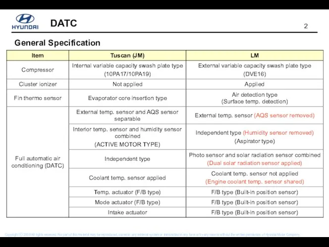
General Specification
General Specification
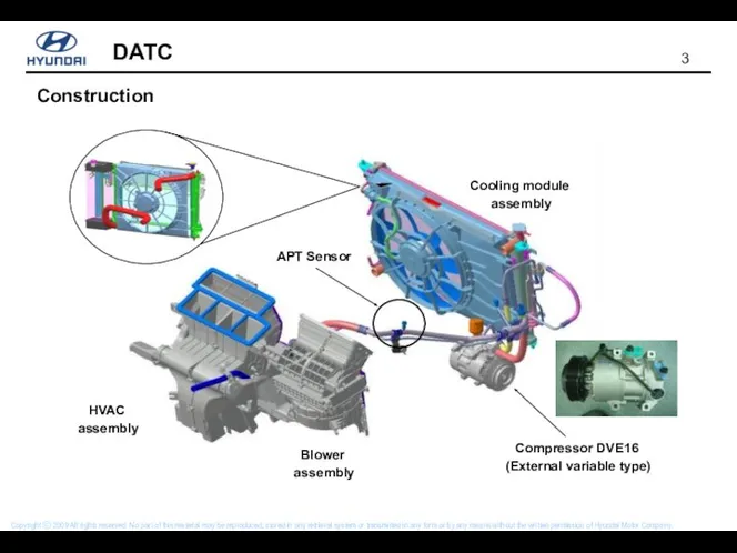
Construction
Construction
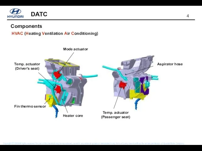
Components
HVAC (Heating Ventilation Air Conditioning)
Components
HVAC (Heating Ventilation Air Conditioning)
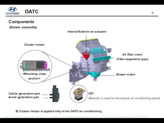
Components
Blower assembly
Interior/Exterior air actuator
Cluster ionizer
Cation generation part
Anion generation part
※
Components
Blower assembly
Interior/Exterior air actuator
Cluster ionizer Cation generation part Anion generation part ※
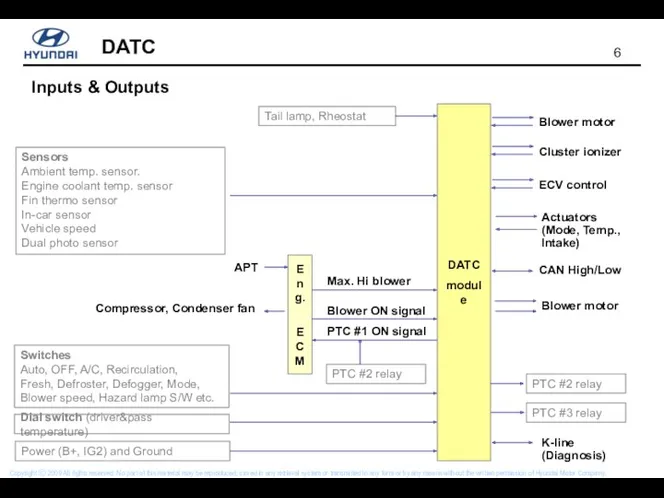
Inputs & Outputs
Tail lamp, Rheostat
Dial switch (driver&pass temperature)
Power (B+, IG2) and
Inputs & Outputs
Tail lamp, Rheostat
Dial switch (driver&pass temperature)
Power (B+, IG2) and
Inputs & Outputs
Tail lamp, Rheostat
Dial switch (driver&pass temperature)
Power (B+, IG2) and
Inputs & Outputs
Tail lamp, Rheostat
Dial switch (driver&pass temperature)
Power (B+, IG2) and
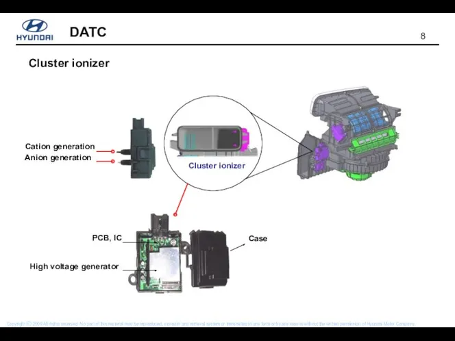
Cluster ionizer
Cluster ionizer
Cation generation
Anion generation
Cluster ionizer
Cluster ionizer
Cation generation
Anion generation
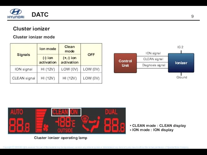
Cluster ionizer
Cluster ionizer mode
CLEAN mode : CLEAN display
ION mode
Cluster ionizer
Cluster ionizer mode
CLEAN mode : CLEAN display
ION mode
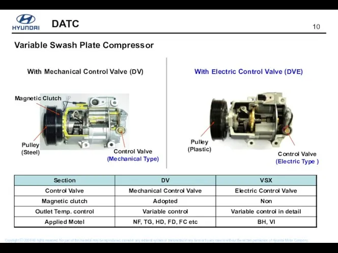
With Mechanical Control Valve (DV)
Control Valve
(Mechanical Type)
Magnetic Clutch
Pulley
(Steel)
With Electric Control
With Mechanical Control Valve (DV)
Control Valve
(Mechanical Type)
Magnetic Clutch
Pulley
(Steel)
With Electric Control
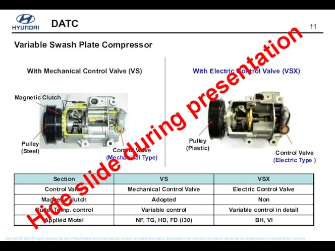
With Mechanical Control Valve (VS)
Control Valve
(Mechanical Type)
Magnetic Clutch
Pulley
(Steel)
With Electric Control
With Mechanical Control Valve (VS)
Control Valve
(Mechanical Type)
Magnetic Clutch
Pulley
(Steel)
With Electric Control
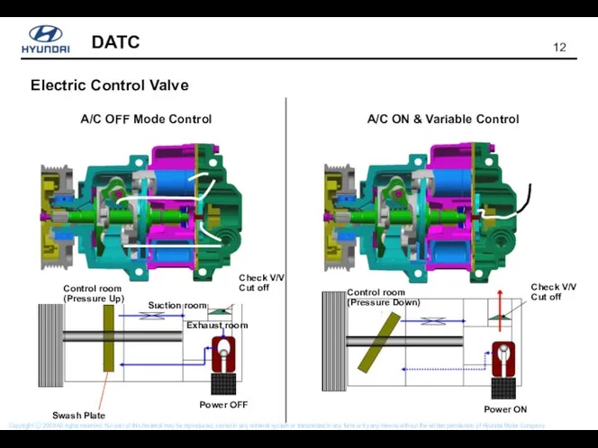
A/C OFF Mode Control
A/C ON & Variable Control
Control room (Pressure Up)
Suction
A/C OFF Mode Control
A/C ON & Variable Control
Control room (Pressure Up)
Suction
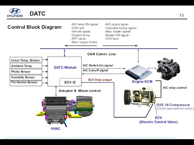
Control Block Diagram
ECV
(Electric Control Valve)
In-car Temp. Sensor
Ambient Temp.
Photo Sensor
Humidity Sensor
Fin thermo
Control Block Diagram
ECV
(Electric Control Valve)
In-car Temp. Sensor
Ambient Temp.
Photo Sensor
Humidity Sensor
Fin thermo
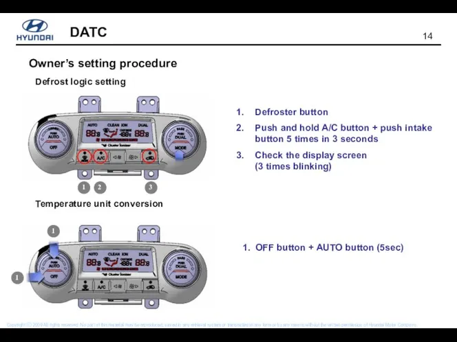
Owner’s setting procedure
Defrost logic setting
Temperature unit conversion
1. OFF button + AUTO
Owner’s setting procedure
Defrost logic setting
Temperature unit conversion
1. OFF button + AUTO
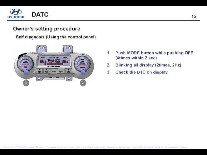
Owner’s setting procedure
Self diagnosis (Using the control panel)
Push MODE button while
Owner’s setting procedure
Self diagnosis (Using the control panel)
Push MODE button while
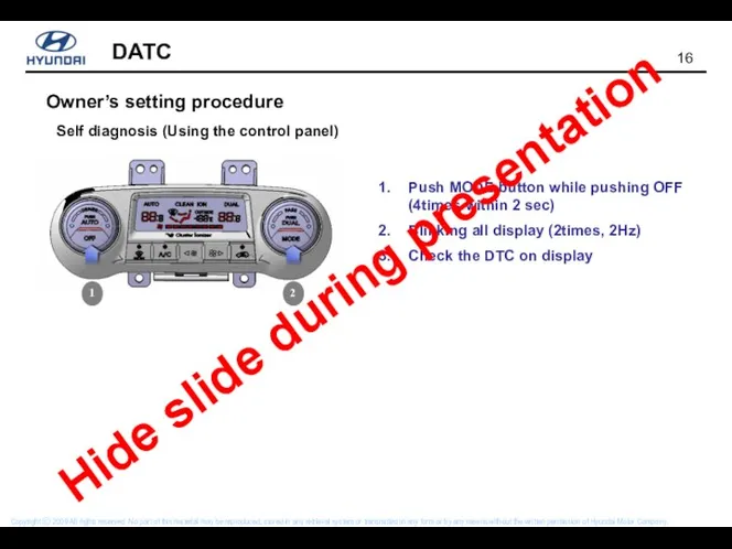
Owner’s setting procedure
Self diagnosis (Using the control panel)
Push MODE button while
Owner’s setting procedure
Self diagnosis (Using the control panel)
Push MODE button while
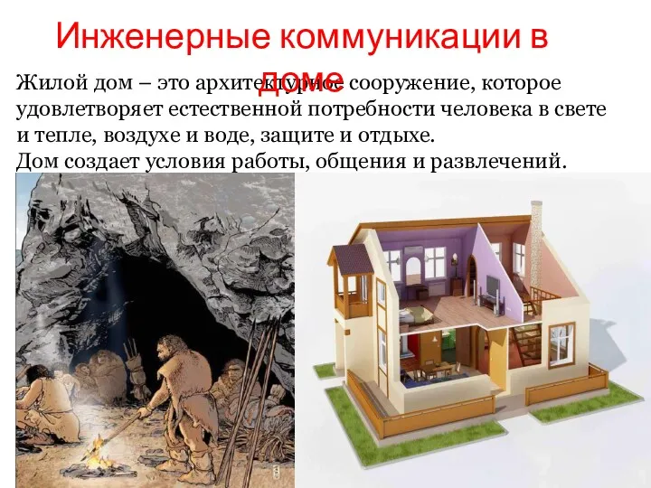 Инженерные коммуникации в доме
 Весенние календарно-обрядовые праздники.
 Factory named by S.M. Kirova JSC
 Памятники сказочным героям
 Основы православной культуры
 Учебные заведения в западной Европе в новое время
 Неотложная помощь в гинекологии
 Средства и приемы трасологического исследования объекта
 Русские обычаи. Праздник Ивана Купалы.
 Особенности проектирования ситуаций действия в деловой игре
 Инновационные процессы в образовании Ростов-на-Дону – 2019
 Чудеса природы
 Обеспечение безопасности технических систем. Лекция 1
 Иммунология. В и Т-лимфоциты и кооперация клеток в иммунном ответе. (Лекция 3)
 Техника челночного бега
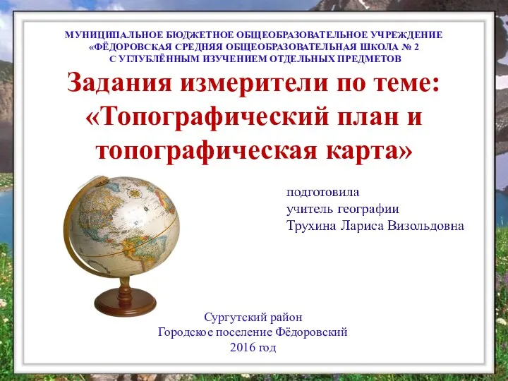 Задания измерители по теме: Топографический план и топографическая карта.
 Отравяния с киселини и основи
 Интерференция света в тонких пленках
 Консультация для воспитателей Я и ребенок
 Характеристика страны Польши
 Лечение острого коронарного синдрома
 Образ семьи в представлении молодежи
 Марийская АССР в годы войны
 Устройство микроскопа и приёмы работы с ним
 Экологические системы
 Кто он, педагог будущего?
 проект Разноцветный мир
 Презентация для родителей по ПДД