- Dialog+ SW 9.xx Hydraulics. Service Training Documentation

Содержание
- 2. Welcome to the Dialog+ Component Overview. Here you will have the opportunity to look at different
- 3. The Sub-Racks are devided in: Low Level Electronics UF Sub-Rack DF Sub-Rack Water Sub-Rack The hydraulics
- 4. Dialog+ Start Hydraulic Flow Diagram Please choose a part of the flow diagram that you would
- 5. Hydraulic Flow Diagram Please choose a part of the flow diagram that you would like to
- 6. Water Sub-Rack Functions of the Water Sub-Rack Controls incoming water amount Degasses the water Heats the
- 7. Pressure Reduction Valve Functions of the Pressure Reduction Valve Reduces ring-line pressure to 0.9 bar Functions
- 8. Water Block Functions of the Water Block Mounting for valves Contains the upline tank Contains the
- 9. Upline Tank Components in the Upline Tank Heat exchanger Float Switch Heater rod Water Sub-Rack Start
- 10. Degassing Valve VEB Functions of the Degassing Valve Creates a restriction in the water flow The
- 11. Heater Rod Functions of the Heater Rod Heats up incoming water Properties of the Heater Rod
- 12. Float Switch Functions of the Float Switch Regulates the water level in the upline tank Turns
- 13. Heat Exchanger Function of the Heat Exchanger Pre-heats the incoming water to increase energy efficiency The
- 14. Degassing Chamber Functions of the Degassing Chamber Allows water to degas Slow flow of water Contains
- 15. Degassing Pressure Sensor Functions of the Degassing Pressure Sensor Measure the degassing pressure Feedback for the
- 16. Degassing Circuit The Flow Path of the Water Water is taken from the upline tank If
- 17. Functions of the Degassing Pump Degasses the water Creates a negative pressure Degassing Pump, Micropump Vers.
- 18. Degassing Pump Functions of the Degassing Pump Creates a negative degassing pressure Pumps fluid with two
- 19. Degassing Motor Functions of the Degassing Motor Drives the degassing pump Onboard driving circuits Is regulated
- 20. Degassing Motor Cover Functions of the Degassing Motor Cover Protects the moving parts of the motor
- 21. Degassing Adapter Block Function of the Adapter Block Mounting of the degassing pump O-rings to seal
- 22. Degassing Pump Foot Piece Functions of the Foot Piece Holds the degassing pump module Absorbs vibrations
- 23. RVDA Functions of the RVDA Ensures a minimum pressure of 400 mmHg on the balance chamber
- 24. RVDA Rear view of the RVDA Pay attention to the assembly direction Water Sub-Rack Start Back
- 25. DF Sub-Rack Functions of the DF Sub-Rack Contains the pumps that push water in and out
- 26. Inlet Flow Pump Functions of the FPE Pumps fresh dialysate into the balance chamber Pumps used
- 27. Outlet Flow Pump Functions of the FPA Pumps used dialysate from the dialyser to the balance
- 28. DF Block Functions of the DF Block Measures conductivity Measures temperature Mixes the dialysate fluid DF
- 29. DF Block Functions of the DF Block Measures conductivity Measures temperature Mixes the dialysate fluid DF
- 30. DF Block Functions of the DF Block Measures conductivity Measures temperature Mixes the dialysate fluid DF
- 31. RVB & RVK Functions of RVB and RVK Absorbs the shock from the piston pumps This
- 32. Concentrate and Bicarbonate Pumps Pump Functions Pumps concentrate and bicarbonate into the DF block Normal speed
- 33. Working concept of the Piston Pump Fluid is sucked in on the one side of the
- 34. RVFPE Functions of the RVFPE Prevents an over pressure Set to 1.3 bar Prevents tubes from
- 35. UF Pump UF Pump Functions Pumps the UF volume to drain Removes fluid from the patient
- 36. Temperature Sensors Functions of TSD_S Measures the temperature for ENDLF_S Is used to compensate the conductivity
- 37. Turbulance Spacer Functions of the Turbulance Spacer Creates turbulance on the temperature sensor Removes dead spaces
- 38. ENDLF Functions of the Final Conductivity Sensor Measures the final conductivity The conductivity controls the speed
- 39. ENDLF_S Functions of the Final Conductivity Sensor for the Supervisor Measures the final conductivity Is dependent
- 40. BICLF Functions of the Bicarbonate Conductivity Sensor Measures bicarbonate conductivity The conductivity controls the speed of
- 41. Conductivity Sensors Functions of the conductivity cells ENDLF measures the final conductivity ENDLF_S supervises the ENDLF
- 42. O-Rings of the Disinfection Valve Function of the O-Rings Lower O-ring: seals off the disinfection port
- 43. Disinfection Valve Functions of the Disinfection Valve Opens when the machine needs to suck in disinfectant
- 44. Sub-Rack Start FPA Adapter Block Functions of the FPA Adapter Block Mounts the FPA Absorbs vibrations
- 45. Rinsing Bridge Start Light Barrier Function of the Light Barrier Senses the position of the disinfection
- 46. Pressure Sensor Dialysate Functions of PDA Measures the dialysate pressure This is used to calculate TMP
- 47. Rinsing Bridge Functions of the Rinsing Bridge Contains the disinfection valve Contains the dialysate pressure sensor
- 48. Rinsing Bridge Sensors Function of the Sensors Detects whether the dialyser couplings are connected to the
- 49. Servo Motor and Controller Board Function of the Servo Motor The motor opens and closes the
- 50. FPE Motor Cover Functions of the FPE Motor Cover Protects the moving parts of the motor
- 51. FPE Motor Functions of the FPE Motor Drives the Flow Pump Inlet pump Onboard driving circuits
- 52. FPA Motor Functions of the FPA Motor Drives the outlet pump Onboard driving circuits Is regulated
- 53. FPA Motor Cover Functions of the FPA Motor Cover Protects the moving parts of the motor
- 54. FPE Adapter Block Functions of the FPE Adapter Block Mounts the FPE Absorbs vibrations for noise
- 55. FPE, Micropump Vers. 1 Functions of the FPE Pump Creates a positive pressure to refill the
- 56. FPA, Micropump Vers. 1 Functions of the FPA Pump Creates a positive pressure to fill the
- 57. UF Sub-Rack Functions of the UF Sub-Rack Contains the balance chamber Is responsible for controlling the
- 58. Air Separator Functions of the Air Separator Prevents air from entering the balance chamber Contains VLA
- 59. Air Separator Functions of the Air Separator Prevents air from entering the balance chamber Contains VLA
- 60. Air Separator Functions of the Air Separator There are 2 pins that sense the level of
- 61. Balance Chamber Functions of the Balance Chamber Consists of 2 chambers, with 8 valves Induction coils
- 62. Balance Chamber Membrane Functions of the Balance Chamber Membrane Separates fresh and used dialysate Controls incoming
- 63. Membrane Position Sensor Functions of the membrane position sensor Measures the position of the membrane Uses
- 64. Bicarbonate Cartridge Holder Please select a part of the catridge holder that you want to look
- 65. Mounting The cartridge holder is fixed to the housing using 2 screws. These screws are accessable
- 66. Swivel Arm Functions of the swivel arm Closes the bicarbonate circuit when no cartride is inserted
- 67. Check Valve The check valve is opened when a cartridge or the swivel arm is inserted.
- 68. Temperature Regulation The temperature regulation is done by the following components TSE TSHE TSD TSDE Start
- 69. Temperature Regulation The first temperature regulation is done with TSE. This sensor is used until the
- 70. Temperature Regulation Once the temperature is stable at TSE, the controller starts to regulate the temperature
- 71. Temperature Regulation Depending on Bypass or Mainflow the machine will use TSDE to regulate the final
- 72. Temperature Regulation If the machine is switched to bypass, TSD will take over regulation of the
- 73. Temperature Regulation At all times during the therapy TSD-S is active to ensure patient safety. The
- 74. Conductivity Regulation Controller Sensors TSBIC & BICLF TSD & ENDLF Start Back Next Supervisor Sensors TSD-S
- 75. The main components of the dialysate preparation are the bicarbonate concentrate pump BICP and the concentrate
- 76. FPE pumps dialysate into the balance chamber Conductivity Regulation DF Sub-Rack Start Back Next Previous
- 77. The BICP adds bicarbonate to the RO water. The pump speed regulated by the conductivity at
- 78. The KP adds concentrate to the Bicarbonate and RO water. The pump speed is regulated by
- 79. RVB and RVK are non-return valves that stablise the concentrate flow. Conductivity Regulation DF Sub-Rack Start
- 80. Temperature fluctuations cause a change in the conductivity measurements. Each conductivity sensor has a separate temperature
- 81. TDS-S and ENDLF-S are used by the Supervisor only.They have no influence on the regulation of
- 82. Dialysate Preparation with BIC Cartridge Option Start Back Next
- 83. Dialysate Preparation with BIC Cartridge DF Sub-Rack Start Back Next
- 84. Filling the Cartridge DF Sub-Rack Start Back Next
- 85. Expeling Air from the Cartridge DF Sub-Rack Start Back Next
- 86. Emptying the Cartridge DF Sub-Rack Start Back
- 87. What compenent is not part of the water sub-rack? Welcome to the Dialog+ Component Overview. Here
- 88. Dialog+ Hydraulic Test Question 2 How many temperature sensors are in the machine? 4 5 6
- 89. Dialog+ Hydraulic Test Question 3 What is the status of the degassing valve during disinfection? Closed
- 90. Dialog+ Hydraulic Test Question 4 Which pump is responsible for pumping fresh dialysate fluid into the
- 91. Dialog+ Hydraulic Test Question 5 What is the pressure of RVDA set to on a standard
- 92. Dialog+ Hydraulic Test Question 6 Wat is the approx. speed for EP, FPE, FPA during therapy?
- 93. Dialog+ Hydraulic Test Test Completed All the letters that have turned dark green were answered correctly.
- 94. Chemical Thermal Disinfection All pumps are running 3 min rinsing and heating to 45°C Air Separator
- 95. Chemical Thermal Disinfection All pumps are running Minimum disinfection time, above minimum Temp Dialog+ Next
- 96. Chemical Thermal Disinfection VBICP Test phase 1 PDA stabilizes close to zero VBICP Test phase 2
- 97. Chemical Thermal Disinfection Rinsing out of disinfectant Dialog+ Back
- 98. Phase 1 From FPE to drain The FPE pumps fresh dialysate into the balance chamber Pressure
- 99. Phase 1 Balance Chamber Start From FPE to drain The FPE pumps fresh dialysate into the
- 100. Phase 1 Balance Chamber Start From FPE to drain The FPE pumps fresh dialysate into the
- 101. Phase 1 Balance Chamber Start From FPE to drain The FPE pumps fresh dialysate into the
- 102. Phase 1 Balance Chamber Start From FPE to drain The FPE pumps fresh dialysate into the
- 103. Phase 1 Balance Chamber Start From FPE to drain The FPE pumps fresh dialysate into the
- 104. Phase 1 Balance Chamber Start From FPE to drain The FPE pumps fresh dialysate into the
- 105. Phase 1 Balance Chamber Start From FPE to drain The FPE pumps fresh dialysate into the
- 106. Phase 2 Balance Chamber Start Patient From FPA to patient to FPA The FPE pumps used
- 107. Phase 2 Balance Chamber Start Patient From FPA to patient to FPA The FPE pumps used
- 108. Phase 2 Balance Chamber Start Patient From FPA to patient to FPA The FPE pumps used
- 109. Phase 2 Balance Chamber Start Patient From FPA to patient to FPA The FPE pumps used
- 110. Phase 2 Balance Chamber Start Patient From FPA to patient to FPA The FPE pumps used
- 111. Phase 2 Balance Chamber Start Patient From FPA to patient to FPA The FPE pumps used
- 112. Phase 2 Balance Chamber Start Patient From FPA to patient to FPA The FPE pumps used
- 113. Phase 2 Balance Chamber Start Patient From FPA to patient to FPA The FPE pumps used
- 114. Phase 1 Balance Chamber Start Back Patient
- 115. Phase 1 Balance Chamber Start Back Patient
- 116. Phase 1 Balance Chamber Start Back Patient
- 117. Phase 1 Balance Chamber Start Back Patient
- 118. Phase 1 Balance Chamber Start Back Patient
- 119. Phase 1 Balance Chamber Start Back Patient
- 120. Phase 1 Balance Chamber Start Back Patient
- 121. Phase 1 Balance Chamber Start Back Patient
- 122. Phase 1 Balance Chamber Start Back Patient
- 123. Phase 1 Balance Chamber Start Back Patient
- 124. Phase 1 Balance Chamber Start Back Patient
- 125. Phase 1 Balance Chamber Start Back Patient
- 126. Phase 1 Balance Chamber Start Back Patient
- 127. Phase 1 Balance Chamber Start Back Patient
- 129. Скачать презентацию
 Сложные предложения с различными видами связи (вводный урок). 9 класс
 В гостях у ханты.
 What is Engineering?
 Мировое хозяйство
 Виртуалдық машиналар
 Контрольно-кассовая техника
 Оборудование для производства молочной продукции
 Александр Сергеевич Пушкин
 Устное собеседование по русскому языку
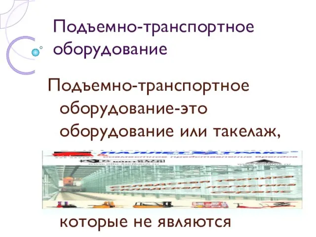 Подъемно-транспортное оборудование
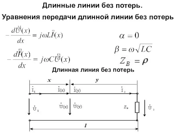 Длинные линии без потерь. Уравнения передачи длинной линии без потерь
 Республика Аргентина
 Презентация по географии в 10 классе по теме Научно-техническая революция и Мировое хозяйство
 Флегмона орбиты
 Социальные взаимодействия
 Классный час, посвященный 70-летию Великой Победы
 Литературное краеведение Оренбургской области. ЗапискиАксакова
 Примеры автономного существования человека в природной среде
 Производственный план
 Презентация к клубному часу Мир, в котором мы живем
 Дидактические игры в 1 классе
 МК ATmel
 Анатомо-физиологические особенности системы крови
 Осенины. Викторина.
 День Победы
 Учет поголовья животных в субъекте
 Зарубежное искусство XX века
 Тема: Культура и быт народов Кубани