- Dialog+SW 9.xx Hydraulics. Technical Support International

Содержание
- 2. Welcome to the Dialog+ Component Overview. Here you will have the opportunity to look at different
- 3. The Sub-Racks are devided in: Electronics UF Sub-Rack DF Sub-Rack Water Sub-Rack The hydraulics of the
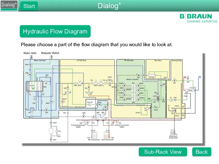
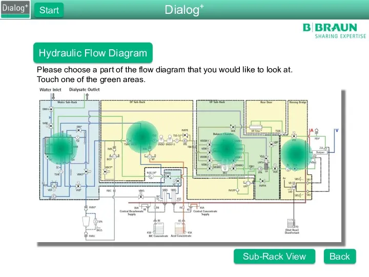
- 4. Dialog+ Start Hydraulic Flow Diagram Please choose a part of the flow diagram that you would
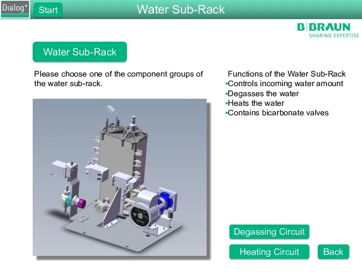
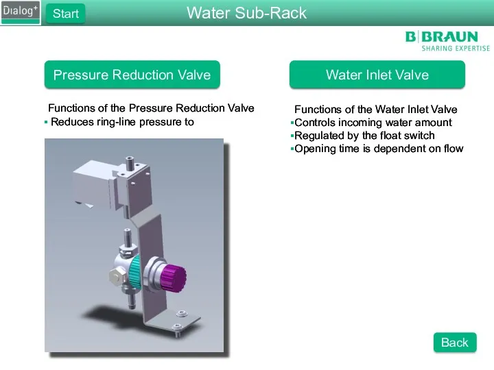
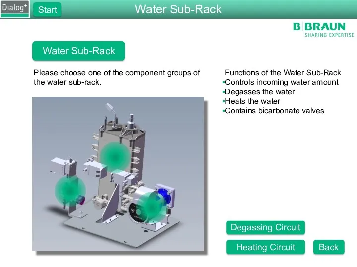
- 5. Water Sub-Rack Please choose one of the component groups of the water sub-rack. Functions of the
- 6. Pressure Reduction Valve Functions of the Pressure Reduction Valve Reduces ring-line pressure to 0.9 bar Functions
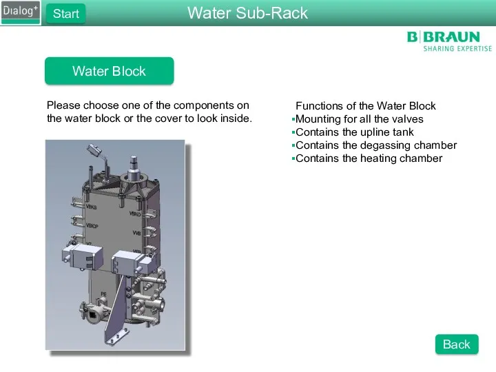
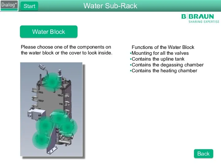
- 7. Water Block Please choose one of the components on the water block or the cover to
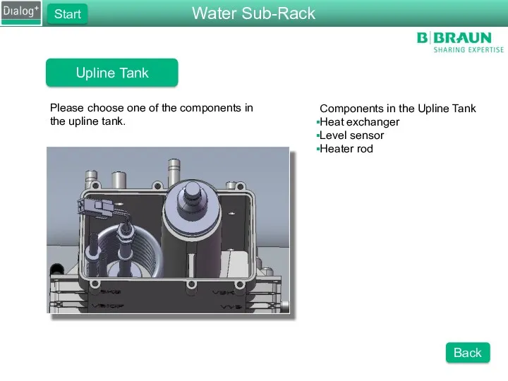
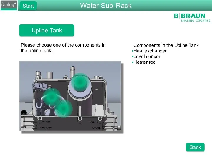
- 8. Upline Tank Please choose one of the components in the upline tank. Components in the Upline
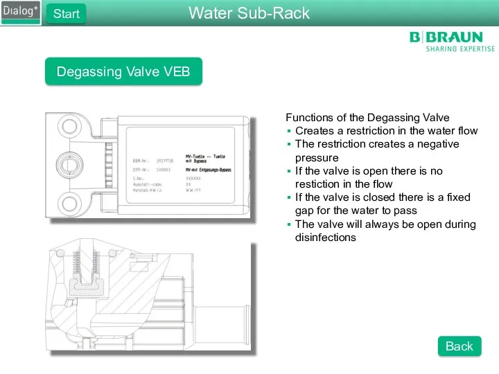
- 9. Degassing Valve VEB Functions of the Degassing Valve Creates a restriction in the water flow The
- 10. Heater Rod Functions of the Heater Rod Heats up incoming water Properties of the Heater Rod
- 11. Float Switch Functions of the Float Switch Regulates the water level in the upline tank Turns
- 12. Heat Exchanger Function of the Heat Exchanger Pre-heats the incoming water to increase energy effeciancy The
- 13. Degassing Chamber Functions of the Degassing Chamber Allows water to degas Slow flow of water Contains
- 14. Degassing Pressure Sensor Functions of the Degassing Pressure Sensor Measure the degassing pressure Feedback for the
- 15. Degassing Circuit The Flow Path of the Water Water is taken from the upline tank If
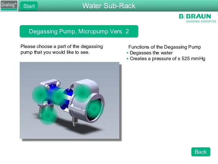
- 16. Degassing Pump, Micropump Vers. 2 Please choose a part of the degassing pump that you would
- 17. Degassing Pump Functions of the Degassing Pump Creates a negative degassing pressure Pumps fluid with two
- 18. Degassing Motor Functions of the Degassing Motor Drives the degassing pump Onboard driving circuits Is regulated
- 19. Degassing Motor Cover Functions of the Degassing Motor Cover Protects the moving parts of the motor
- 20. Degassing Adaptor Block Function of the Adaptor Block Mounting of the degassing pump O-rings to seal
- 21. Degassing Pump Foot Piece Functions of the Foot Piece Holds the degassing pump module Absorbs vibrations
- 22. RVDA Functions of the RVDA Ensures a minimum pressure of 400 mmHg on the balance chamber
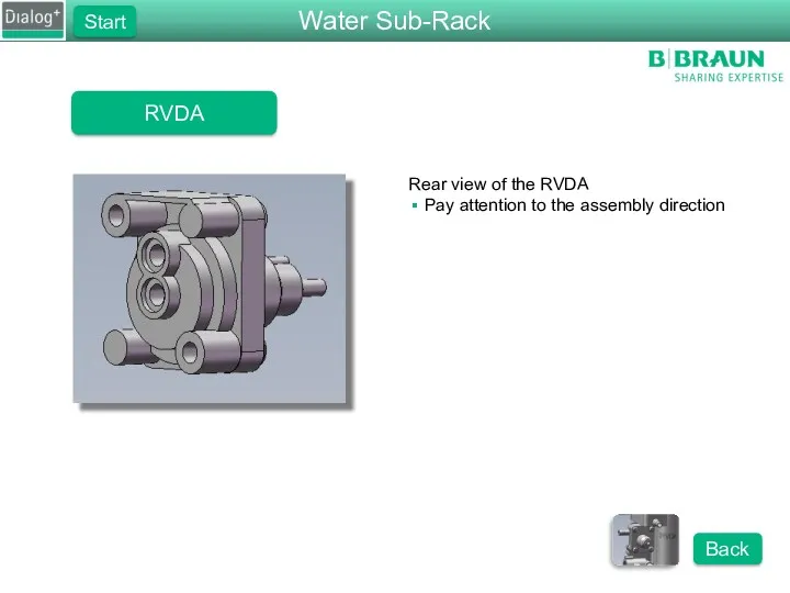
- 23. RVDA Rear view of the RVDA Pay attention to the assembly direction Water Sub-Rack Start Back
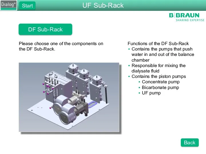
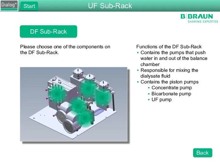
- 24. DF Sub-Rack Please choose one of the components on the DF Sub-Rack. Functions of the DF
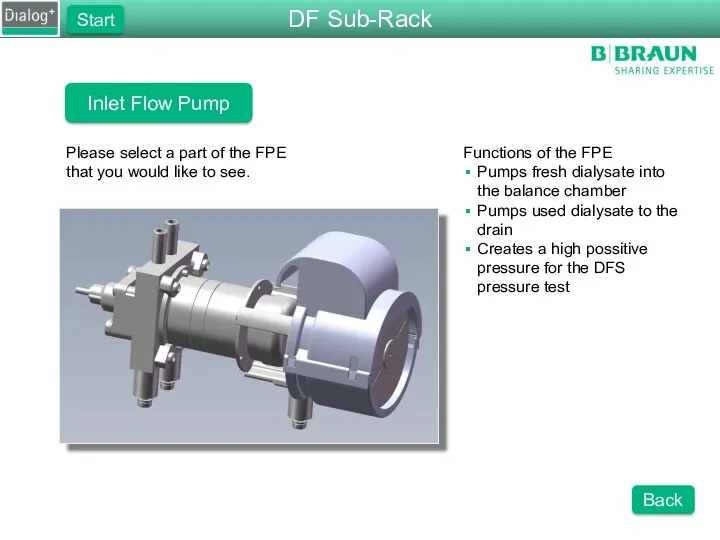
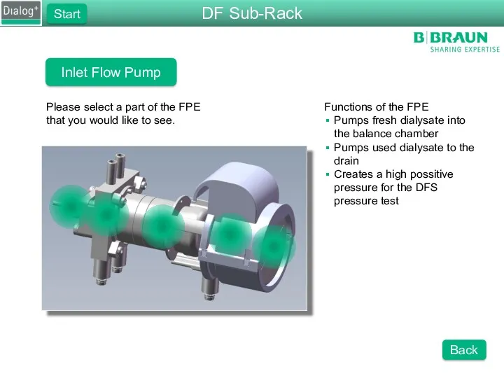
- 25. Inlet Flow Pump Please select a part of the FPE that you would like to see.
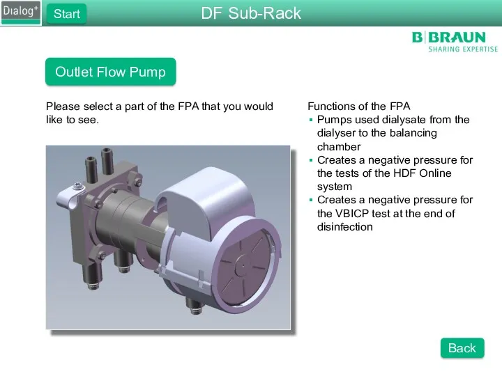
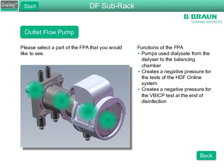
- 26. Outlet Flow Pump Please select a part of the FPA that you would like to see.
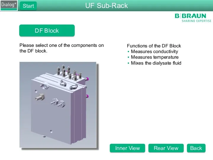
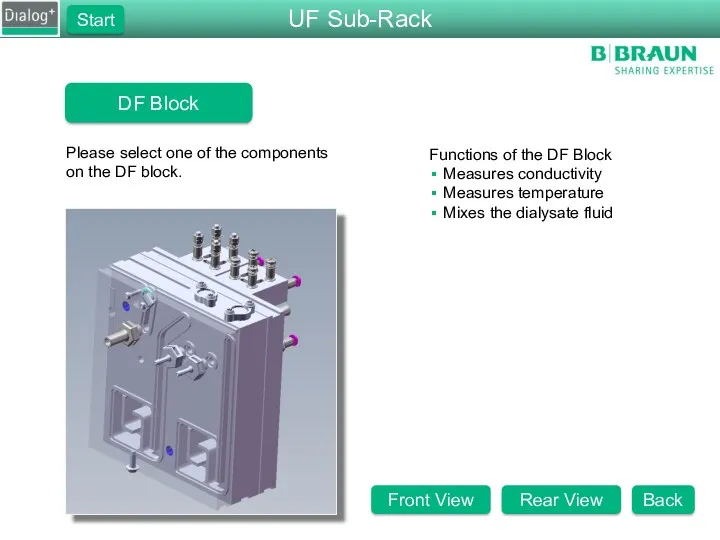
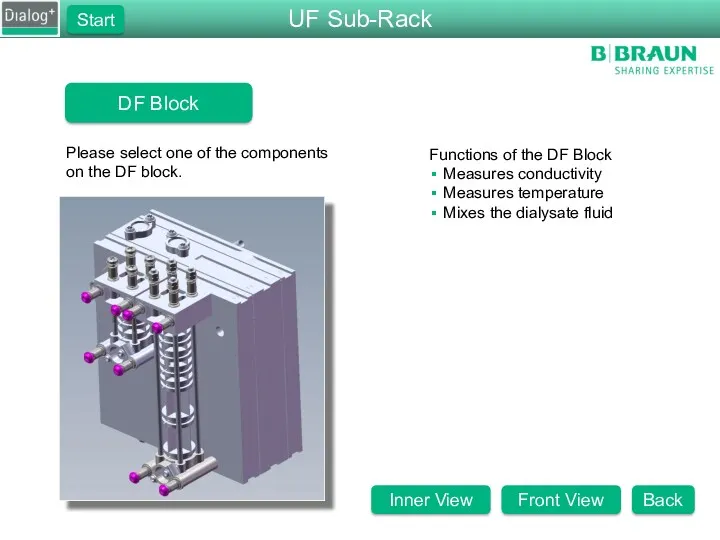
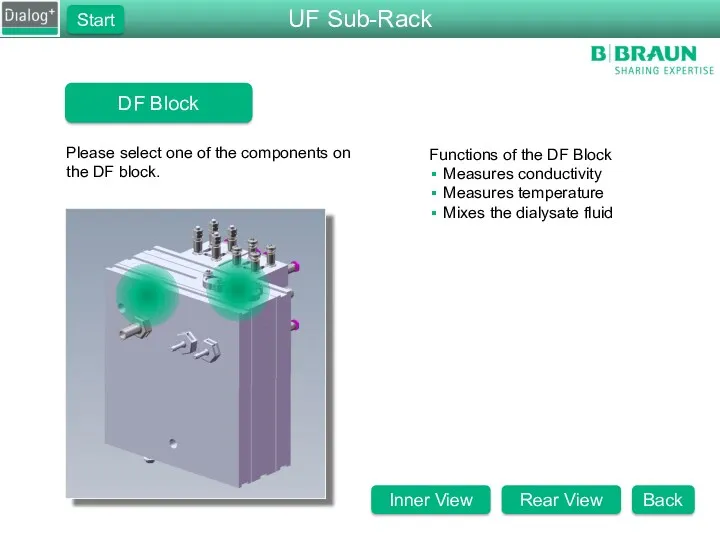
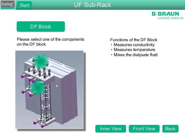
- 27. DF Block Please select one of the components on the DF block. Functions of the DF
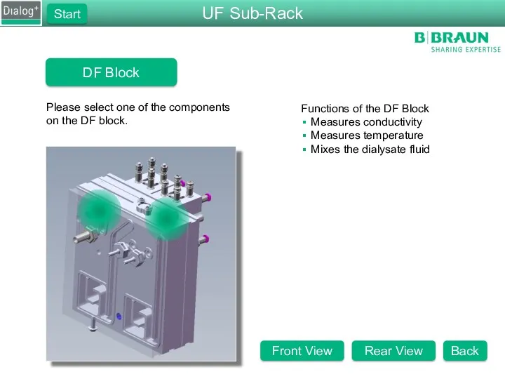
- 28. DF Block Please select one of the components on the DF block. Functions of the DF
- 29. DF Block Please select one of the components on the DF block. Functions of the DF
- 30. RVB & RVK Functions of RVB and RVK Absorbs the shock from the piston pumps This
- 31. Concentrate and Bicarbonate Pumps Pump Functions Pumps concentrate and bicarbonate into the DF block Normal speed
- 32. Working concept of the Piston Pump Fluid is sucked in on the one side of the
- 33. RVFPE Functions of the RVFPE Prevents an over pressure Set to 1.3 bar Prevents tubes from
- 34. Concentrate and Bicarbonate Pumps UF Pump Functions Pumps the UF volume to drain Remove fluid from
- 35. Temperature Sensors Functions of TSD_S Measures the temperature for ENDLF_S Is used to compensate the conductivity
- 36. Terbulance Spacer Functions of the Terbulance Spacer Creates terbulance on the temperature sensor Removes dead spaces
- 37. ENDLF Functions of the Final Conductivity Sensor Measures the final conductivity The conductivity controls the speed
- 38. ENDLF_S Functions of the Final Conductivity Sensor for the Supervisor Measures the final conductivity Is dependent
- 39. BICLF Functions of the Bicarbonate Conductivity Sensor Measures bicarbonate conductivity The conductivity controls the speed of
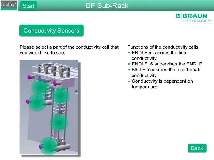
- 40. Conductivity Sensors Functions of the conductivity cells ENDLF measures the final conductivity ENDLF_S supervises the ENDLF
- 41. O-Rings of the Disinfection Valve Function of the O-Rings Lower O-ring: seals of the disinfection port
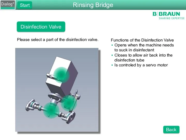
- 42. Disinfection Valve Please select a part of the disinfection valve. Functions of the Disinfection Valve Opens
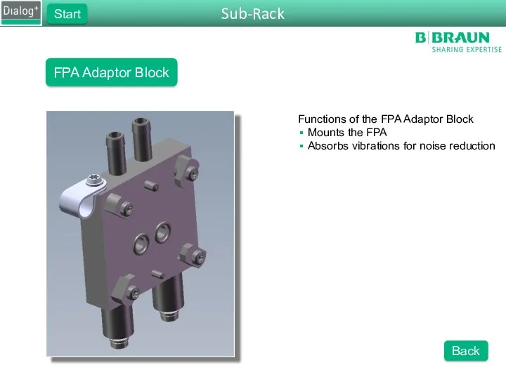
- 43. Sub-Rack Start FPA Adaptor Block Back Functions of the FPA Adaptor Block Mounts the FPA Absorbs
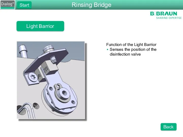
- 44. Rinsing Bridge Start Light Barrior Back Function of the Light Barrior Senses the position of the
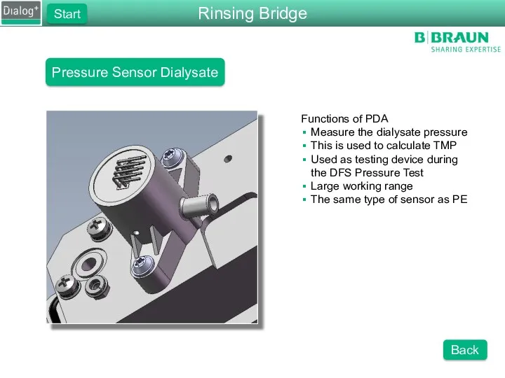
- 45. Pressure Sensor Dialysate Functions of PDA Measure the dialysate pressure This is used to calculate TMP
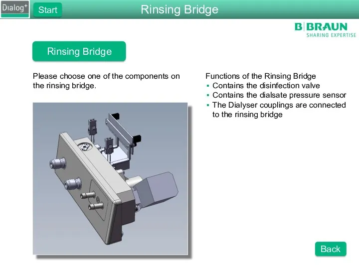
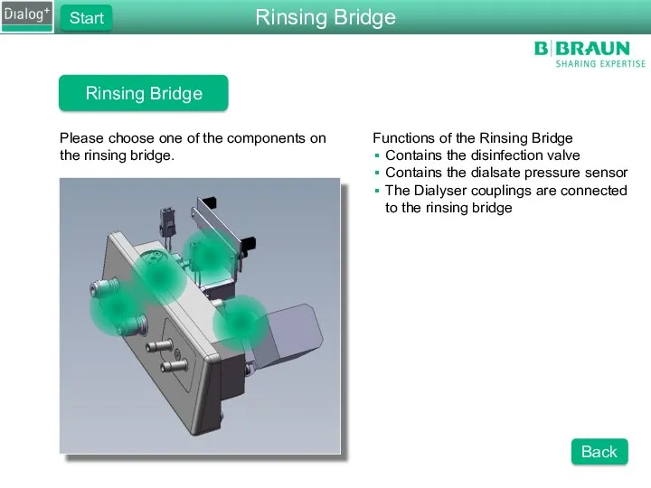
- 46. Rinsing Bridge Please choose one of the components on the rinsing bridge. Functions of the Rinsing
- 47. Rinsing Bridge Sensors Function of the Sensors Detects whether the dialyser couplings are connected to the
- 48. Servo Motor and Controller Board Function of the Servo Motor The motor opens and closes the
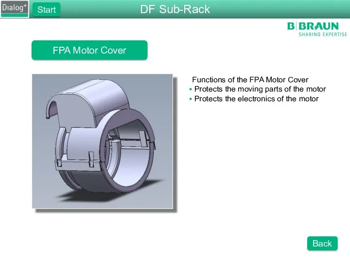
- 49. FPE Motor Cover Functions of the FPE Motor Cover Protects the moving parts of the motor
- 50. FPE Motor Functions of the FPE Motor Drives the degassing pump Onboard driving circuits Is regulated
- 51. FPA Motor Functions of the FPA Motor Drives the degassing pump Onboard driving circuits Is regulated
- 52. FPA Motor Cover Functions of the FPA Motor Cover Protects the moving parts of the motor
- 53. Hydraulic Flow Diagram Please choose a part of the flow diagram that you would like to
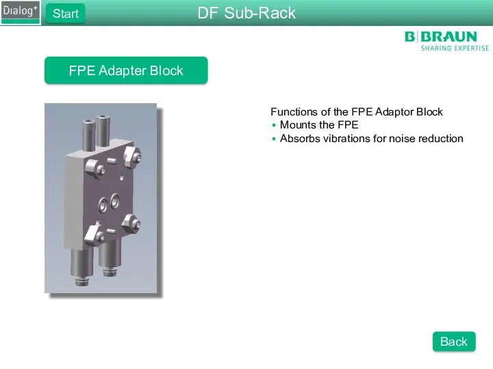
- 54. FPE Adapter Block Functions of the FPE Adaptor Block Mounts the FPE Absorbs vibrations for noise
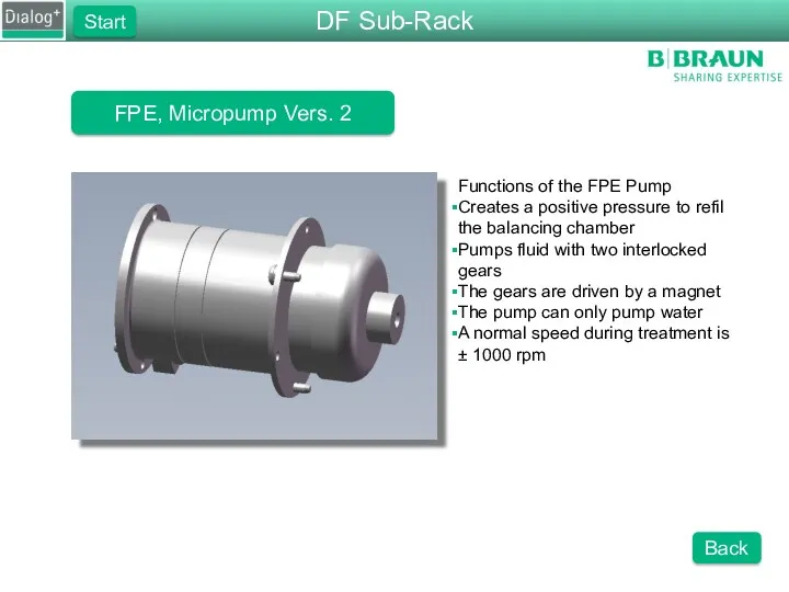
- 55. FPE, Micropump Vers. 2 Functions of the FPE Pump Creates a positive pressure to refil the
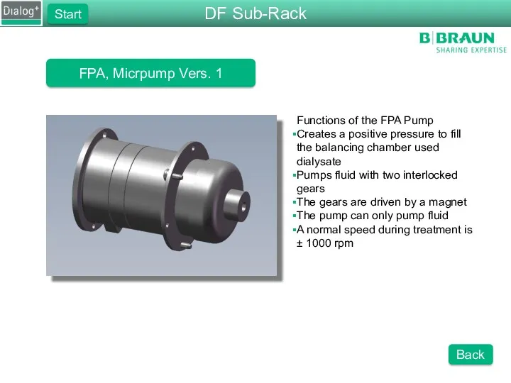
- 56. FPA, Micrpump Vers. 1 Functions of the FPA Pump Creates a positive pressure to fill the
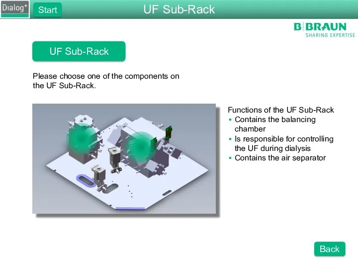
- 57. UF Sub-Rack Please choose one of the components on the UF Sub-Rack. Functions of the UF
- 58. Air Separator Functions of the Air Separator Prevents air from entering the balancing chamber Contains VLA
- 59. Air Separator Functions of the Air Separator Prevents air from entering the balancing chamber Contains VLA
- 60. Air Separator Functions of the Air Separator There are 2 pins that sense the level of
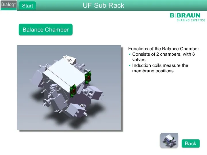
- 61. Balance Chamber Functions of the Balance Chamber Consists of 2 chambers, with 8 valves Induction coils
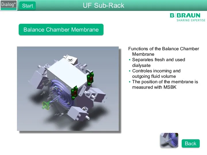
- 62. Balance Chamber Membrane Functions of the Balance Chamber Membrane Separates fresh and used dialysate Controles incoming
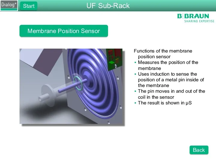
- 63. Membrane Position Sensor Functions of the membrane position sensor Measures the position of the membrane Uses
- 64. Water Sub-Rack Please choose one of the component groups of the water sub-rack. Functions of the
- 65. Water Block Please choose one of the components on the water block or the cover to
- 66. Upline Tank Please choose one of the components in the upline tank. Components in the Upline
- 67. Degassing Pump, Micropump Vers. 2 Please choose a part of the degassing pump that you would
- 68. DF Sub-Rack Please choose one of the components on the DF Sub-Rack. Functions of the DF
- 69. Inlet Flow Pump Please select a part of the FPE that you would like to see.
- 70. Outlet Flow Pump Please select a part of the FPA that you would like to see.
- 71. DF Block Please select one of the components on the DF block. Functions of the DF
- 72. DF Block Please select one of the components on the DF block. Functions of the DF
- 73. DF Block Please select one of the components on the DF block. Functions of the DF
- 74. Conductivity Sensors Functions of the conductivity cells ENDLF measures the final conductivity ENDLF_S supervises the ENDLF
- 75. Disinfection Valve Please select a part of the disinfection valve. Functions of the Disinfection Valve Opens
- 76. Rinsing Bridge Please choose one of the components on the rinsing bridge. Functions of the Rinsing
- 77. UF Sub-Rack Please choose one of the components on the UF Sub-Rack. Functions of the UF
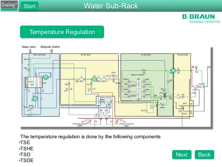
- 78. Temperature Regulation The temperature regulation is done by the following components TSE TSHE TSD TSDE Water
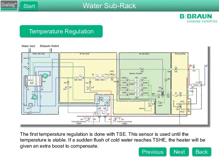
- 79. Temperature Regulation The first temperature regulation is done with TSE. This sensor is used until the
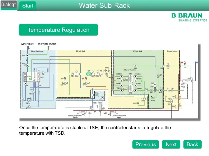
- 80. Temperature Regulation Once the temperature is stable at TSE, the controller starts to regulate the temperature
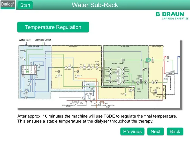
- 81. Temperature Regulation After approx. 10 minutes the machine will use TSDE to regulate the final temperature.
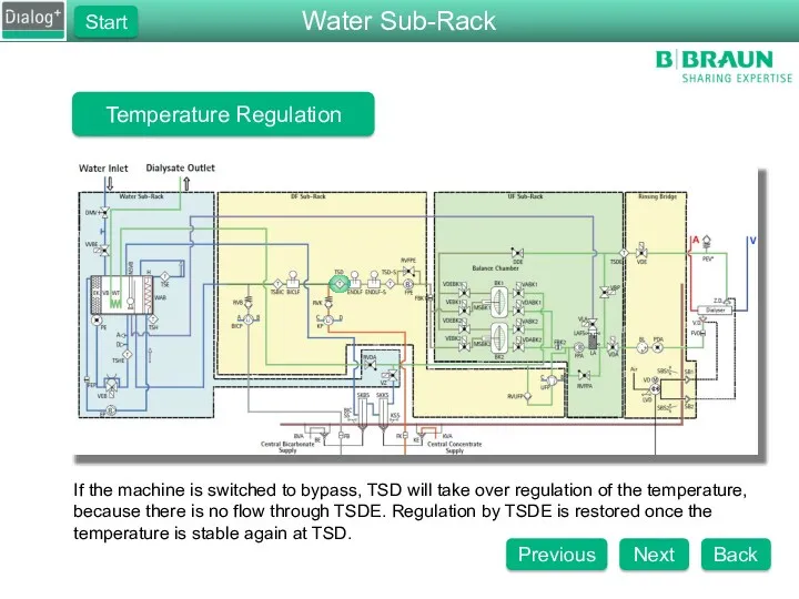
- 82. Temperature Regulation If the machine is switched to bypass, TSD will take over regulation of the
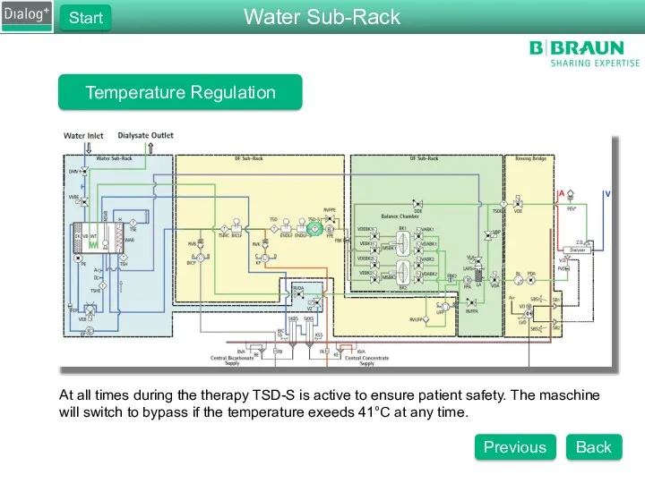
- 83. Temperature Regulation At all times during the therapy TSD-S is active to ensure patient safety. The
- 84. What compenent is not part of the water sub-rack? Welcome to the Dialog+ Component Overview. Here
- 85. Dialog+ Hydraulic Test Question 2 How many temperature sensors are in the machine? 4 5 6
- 86. Dialog+ Hydraulic Test Question 3 What is the status of the degassing valve during disinfection? Closed
- 87. Dialog+ Hydraulic Test Question 4 Which pump is responsable for pumping fresh dialysate fluid into the
- 88. Dialog+ Hydraulic Test Question 5 What is the pressure of RVDA set to on a standard
- 89. Dialog+ Hydraulic Test Question 6 Wat is the approx. speed for EP, FPE, FPA during therapy?
- 90. Dialog+ Hydraulic Test Test Completed Press the Show Results button to find out how many questions
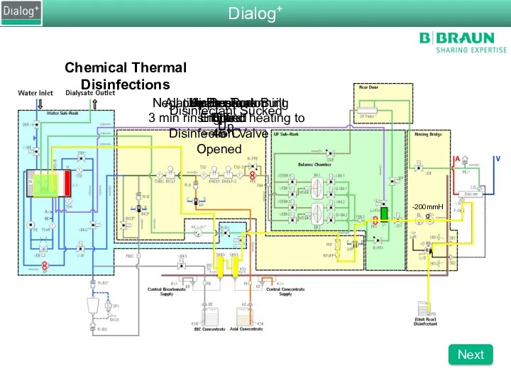
- 91. Chemical Thermal Disinfections All pumps are running 3 min rinsing and heating to 45°C Air Separator
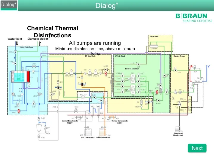
- 92. Chemical Thermal Disinfections All pumps are running Minimum disinfection time, above minimum Temp Dialog+ Next
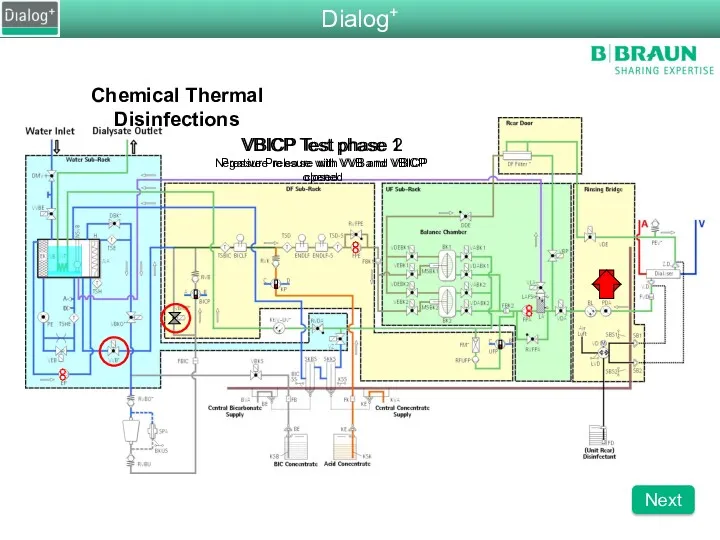
- 93. Chemical Thermal Disinfections VBICP Test phase 1 Negative Pressure with VVB and VBICP closed VBICP Test
- 94. Chemical Thermal Disinfection Rinsing out of disinfectant Dialog+ Back
- 96. Скачать презентацию
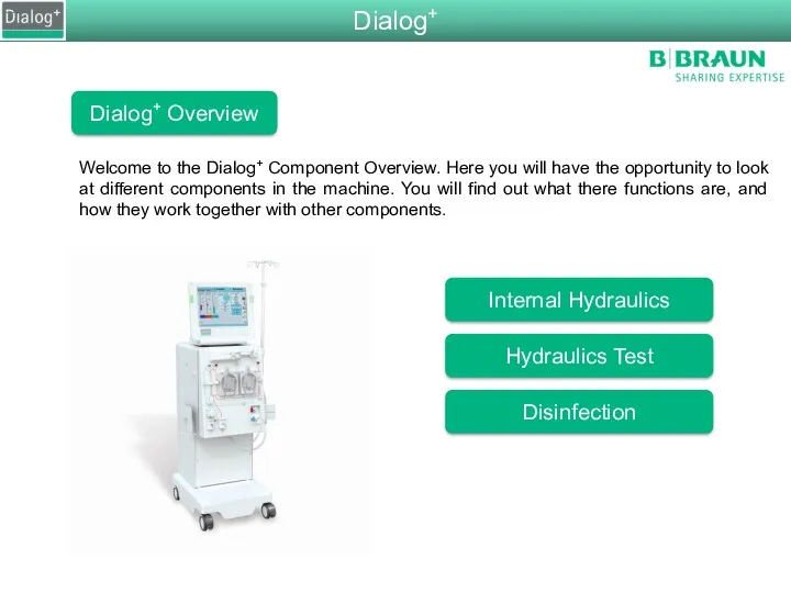
Welcome to the Dialog+ Component Overview. Here you will have the
Welcome to the Dialog+ Component Overview. Here you will have the
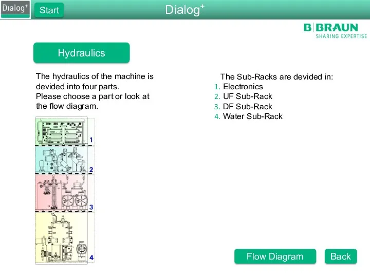
The Sub-Racks are devided in:
Electronics
UF Sub-Rack
DF Sub-Rack
Water
The Sub-Racks are devided in:
Electronics
UF Sub-Rack
DF Sub-Rack
Water
Dialog+
Start
Hydraulic Flow Diagram
Please choose a part of the flow diagram that
Dialog+
Start
Hydraulic Flow Diagram
Please choose a part of the flow diagram that
Water Sub-Rack
Please choose one of the component groups of the water
Water Sub-Rack
Please choose one of the component groups of the water
Pressure Reduction Valve
Functions of the Pressure Reduction Valve
Reduces ring-line pressure
Pressure Reduction Valve
Functions of the Pressure Reduction Valve
Reduces ring-line pressure
Water Block
Please choose one of the components on the water block
Water Block
Please choose one of the components on the water block
Upline Tank
Please choose one of the components in the upline tank.
Components
Upline Tank
Please choose one of the components in the upline tank.
Components
Degassing Valve VEB
Functions of the Degassing Valve
Creates a restriction in the
Degassing Valve VEB
Functions of the Degassing Valve
Creates a restriction in the
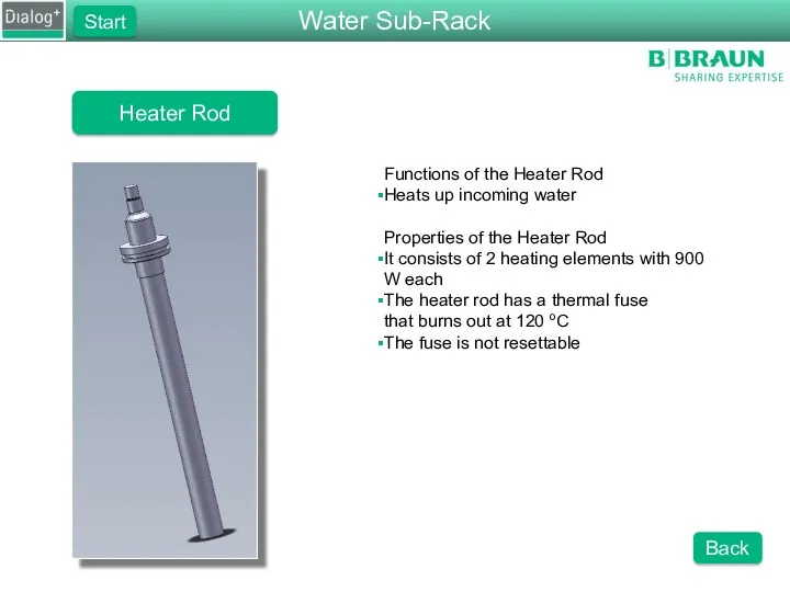
Heater Rod
Functions of the Heater Rod
Heats up incoming water
Properties of the
Heater Rod
Functions of the Heater Rod
Heats up incoming water
Properties of the
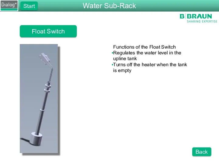
Float Switch
Functions of the Float Switch
Regulates the water level in the
Float Switch
Functions of the Float Switch
Regulates the water level in the
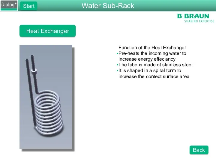
Heat Exchanger
Function of the Heat Exchanger
Pre-heats the incoming water to increase
Heat Exchanger
Function of the Heat Exchanger
Pre-heats the incoming water to increase
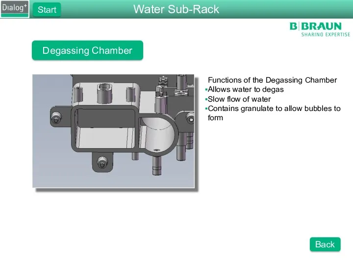
Degassing Chamber
Functions of the Degassing Chamber
Allows water to degas
Slow flow of
Degassing Chamber
Functions of the Degassing Chamber
Allows water to degas
Slow flow of
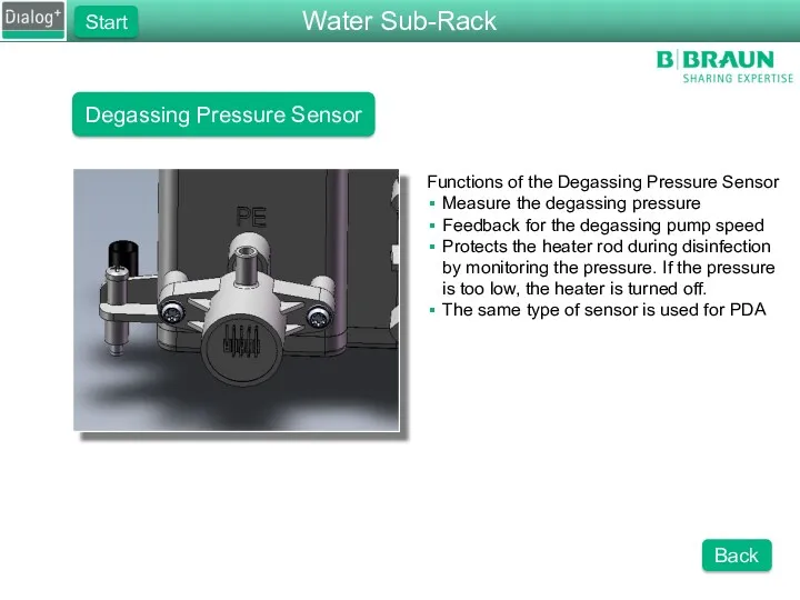
Degassing Pressure Sensor
Functions of the Degassing Pressure Sensor
Measure the degassing pressure
Feedback
Degassing Pressure Sensor
Functions of the Degassing Pressure Sensor
Measure the degassing pressure
Feedback
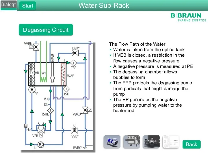
Degassing Circuit
The Flow Path of the Water
Water is taken from the
Degassing Circuit
The Flow Path of the Water
Water is taken from the
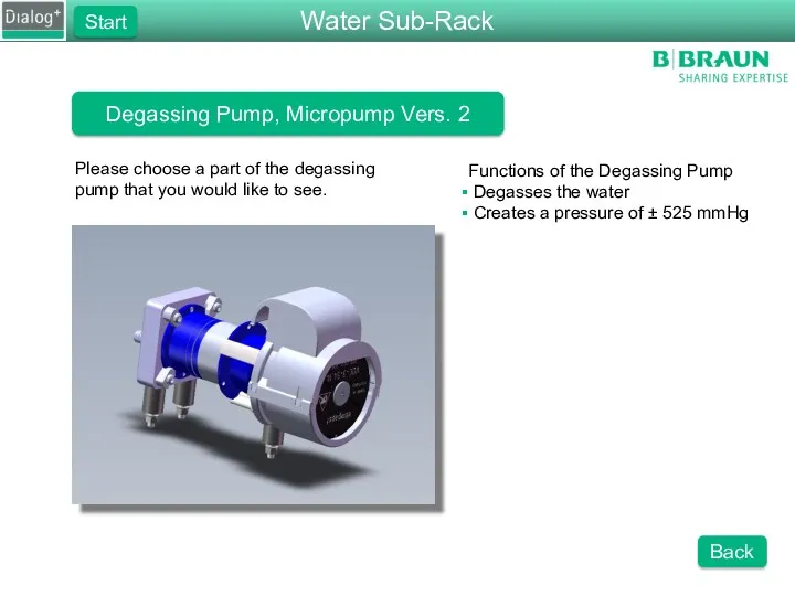
Degassing Pump, Micropump Vers. 2
Please choose a part of the degassing
Degassing Pump, Micropump Vers. 2
Please choose a part of the degassing
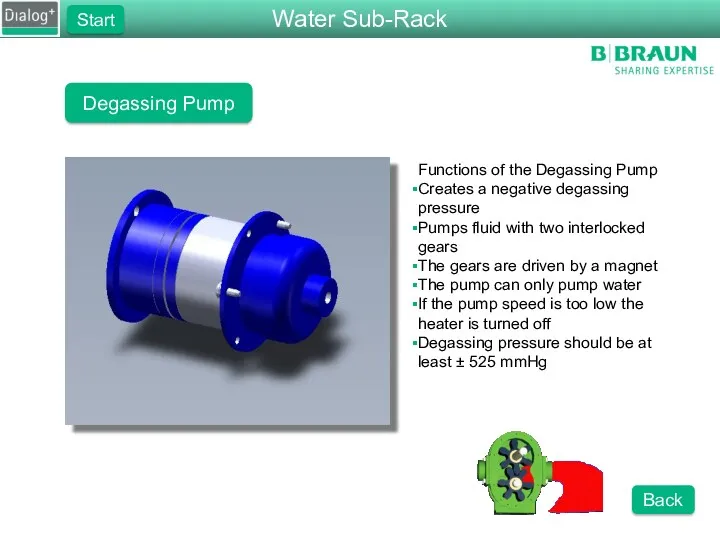
Degassing Pump
Functions of the Degassing Pump
Creates a negative degassing pressure
Pumps fluid
Degassing Pump
Functions of the Degassing Pump
Creates a negative degassing pressure
Pumps fluid
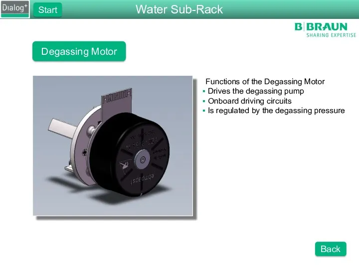
Degassing Motor
Functions of the Degassing Motor
Drives the degassing pump
Onboard
Degassing Motor
Functions of the Degassing Motor
Drives the degassing pump
Onboard

Degassing Motor Cover
Functions of the Degassing Motor Cover
Protects the moving
Degassing Motor Cover
Functions of the Degassing Motor Cover
Protects the moving
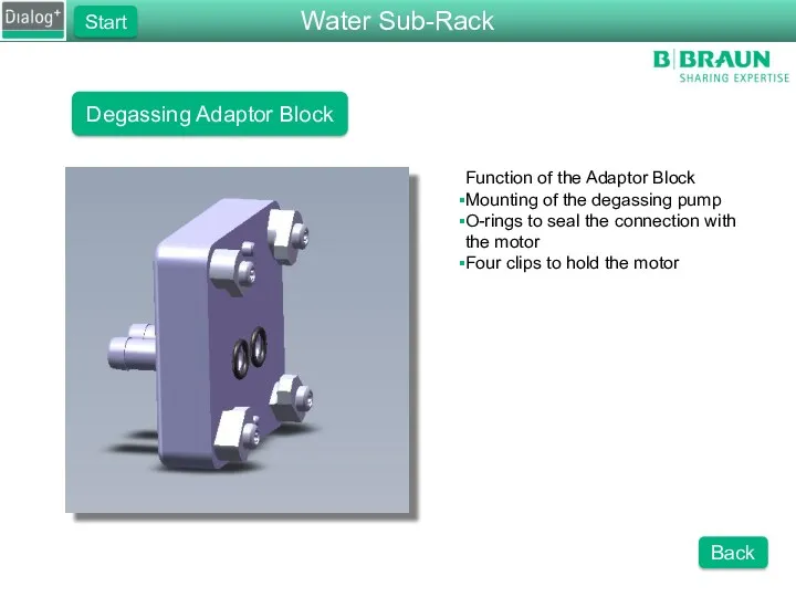
Degassing Adaptor Block
Function of the Adaptor Block
Mounting of the degassing pump
O-rings
Degassing Adaptor Block
Function of the Adaptor Block
Mounting of the degassing pump
O-rings
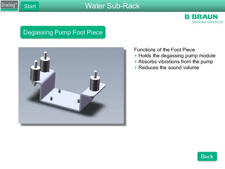
Degassing Pump Foot Piece
Functions of the Foot Piece
Holds the degassing pump
Degassing Pump Foot Piece
Functions of the Foot Piece
Holds the degassing pump
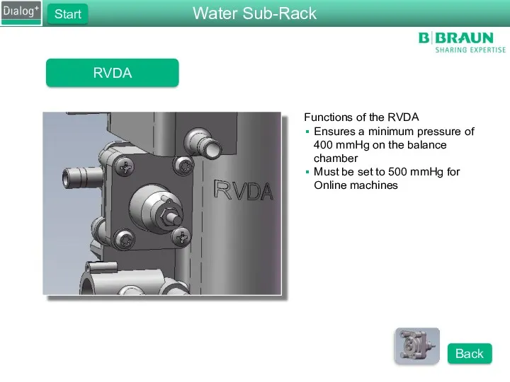
RVDA
Functions of the RVDA
Ensures a minimum pressure of 400 mmHg on
RVDA
Functions of the RVDA
Ensures a minimum pressure of 400 mmHg on
RVDA
Rear view of the RVDA
Pay attention to the assembly direction
Water Sub-Rack
Start
Back
RVDA
Rear view of the RVDA
Pay attention to the assembly direction
Water Sub-Rack
Start
Back
DF Sub-Rack
Please choose one of the components on the DF Sub-Rack.
Functions
DF Sub-Rack
Please choose one of the components on the DF Sub-Rack.
Functions
Inlet Flow Pump
Please select a part of the FPE that
Inlet Flow Pump
Please select a part of the FPE that
Outlet Flow Pump
Please select a part of the FPA that you
Outlet Flow Pump
Please select a part of the FPA that you
DF Block
Please select one of the components on the DF block.
Functions
DF Block
Please select one of the components on the DF block.
Functions
DF Block
Please select one of the components on the DF block.
Functions
DF Block
Please select one of the components on the DF block.
Functions
DF Block
Please select one of the components on the DF block.
Functions
DF Block
Please select one of the components on the DF block.
Functions
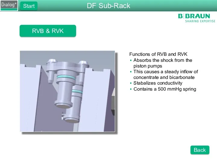
RVB & RVK
Functions of RVB and RVK
Absorbs the shock from the
RVB & RVK
Functions of RVB and RVK
Absorbs the shock from the
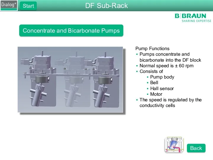
Concentrate and Bicarbonate Pumps
Pump Functions
Pumps concentrate and bicarbonate into the DF
Concentrate and Bicarbonate Pumps
Pump Functions
Pumps concentrate and bicarbonate into the DF
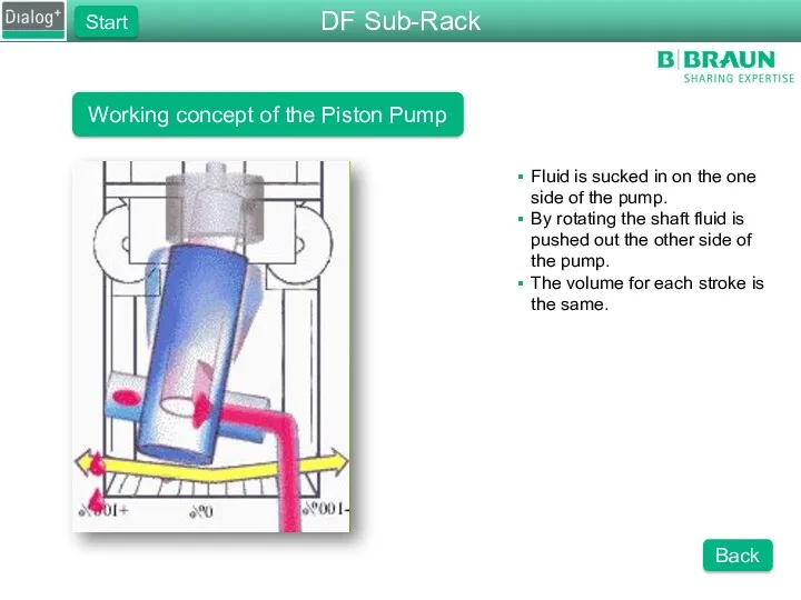
Working concept of the Piston Pump
Fluid is sucked in on the
Working concept of the Piston Pump
Fluid is sucked in on the
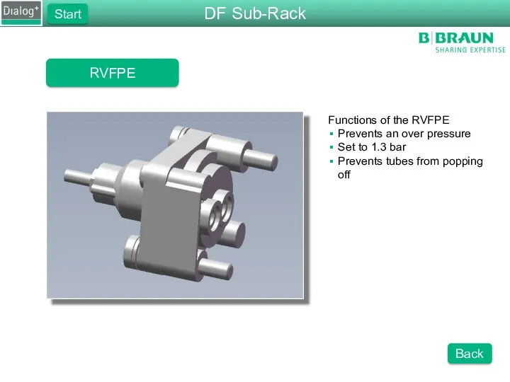
RVFPE
Functions of the RVFPE
Prevents an over pressure
Set to 1.3 bar
Prevents tubes
RVFPE
Functions of the RVFPE
Prevents an over pressure
Set to 1.3 bar
Prevents tubes
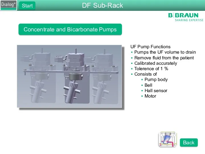
Concentrate and Bicarbonate Pumps
UF Pump Functions
Pumps the UF volume to drain
Remove
Concentrate and Bicarbonate Pumps
UF Pump Functions
Pumps the UF volume to drain
Remove
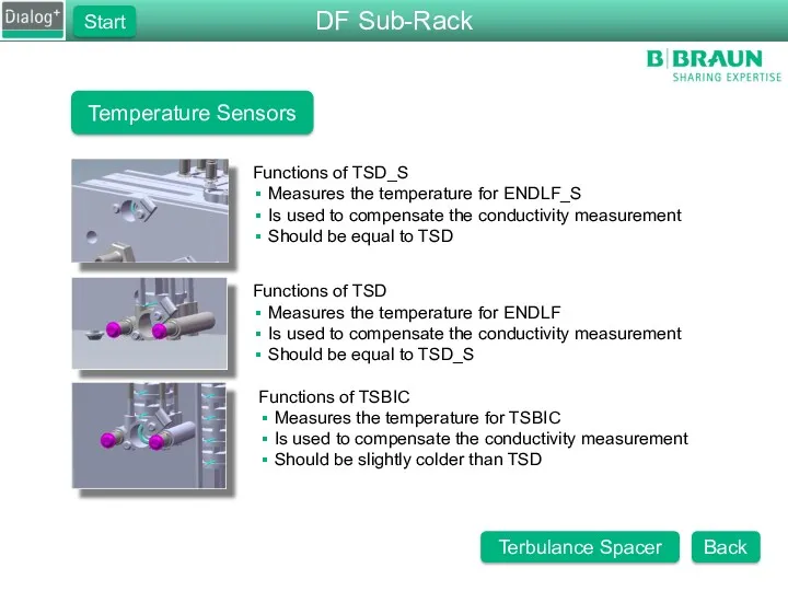
Temperature Sensors
Functions of TSD_S
Measures the temperature for ENDLF_S
Is used to compensate
Temperature Sensors
Functions of TSD_S
Measures the temperature for ENDLF_S
Is used to compensate
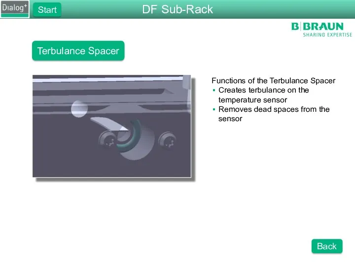
Terbulance Spacer
Functions of the Terbulance Spacer
Creates terbulance on the temperature sensor
Removes
Terbulance Spacer
Functions of the Terbulance Spacer
Creates terbulance on the temperature sensor
Removes
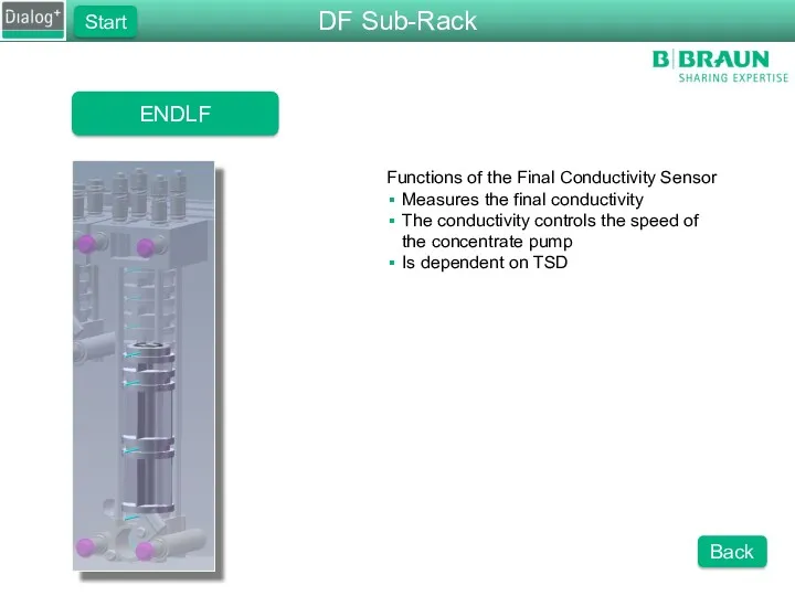
ENDLF
Functions of the Final Conductivity Sensor
Measures the final conductivity
The conductivity controls
ENDLF
Functions of the Final Conductivity Sensor
Measures the final conductivity
The conductivity controls
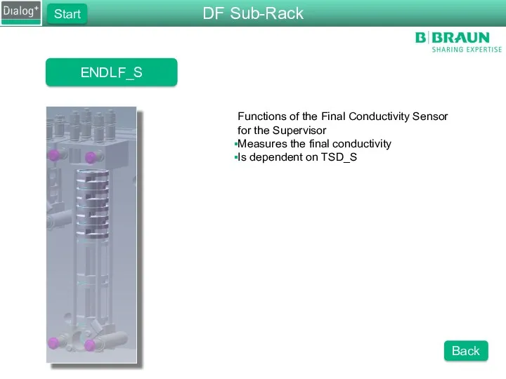
ENDLF_S
Functions of the Final Conductivity Sensor
for the Supervisor
Measures the final conductivity
Is
ENDLF_S
Functions of the Final Conductivity Sensor
for the Supervisor
Measures the final conductivity
Is
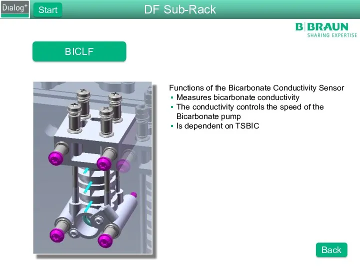
BICLF
Functions of the Bicarbonate Conductivity Sensor
Measures bicarbonate conductivity
The conductivity controls the
BICLF
Functions of the Bicarbonate Conductivity Sensor
Measures bicarbonate conductivity
The conductivity controls the
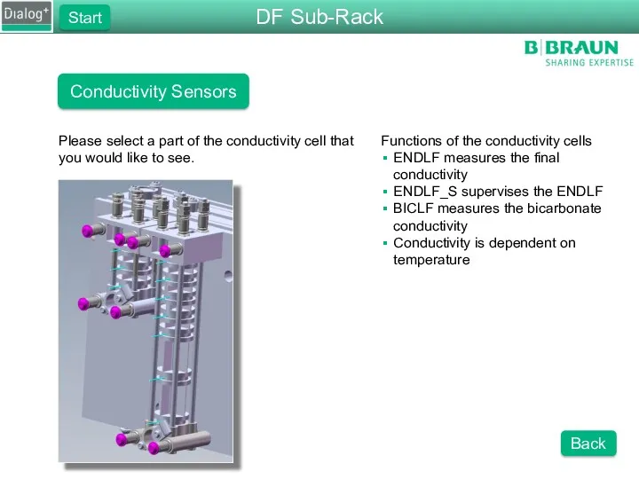
Conductivity Sensors
Functions of the conductivity cells
ENDLF measures the final conductivity
ENDLF_S supervises
Conductivity Sensors
Functions of the conductivity cells
ENDLF measures the final conductivity
ENDLF_S supervises
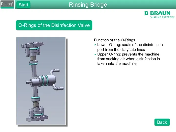
O-Rings of the Disinfection Valve
Function of the O-Rings
Lower O-ring: seals of
O-Rings of the Disinfection Valve
Function of the O-Rings
Lower O-ring: seals of
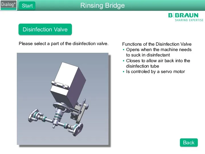
Disinfection Valve
Please select a part of the disinfection valve.
Functions of the
Disinfection Valve
Please select a part of the disinfection valve.
Functions of the
Sub-Rack
Start
FPA Adaptor Block
Back
Functions of the FPA Adaptor Block
Mounts the FPA
Absorbs vibrations
Sub-Rack
Start
FPA Adaptor Block
Back
Functions of the FPA Adaptor Block
Mounts the FPA
Absorbs vibrations
Rinsing Bridge
Start
Light Barrior
Back
Function of the Light Barrior
Senses the position of the
Rinsing Bridge
Start
Light Barrior
Back
Function of the Light Barrior
Senses the position of the
Pressure Sensor Dialysate
Functions of PDA
Measure the dialysate pressure
This is used to
Pressure Sensor Dialysate
Functions of PDA
Measure the dialysate pressure
This is used to
Rinsing Bridge
Please choose one of the components on the rinsing bridge.
Functions
Rinsing Bridge
Please choose one of the components on the rinsing bridge.
Functions
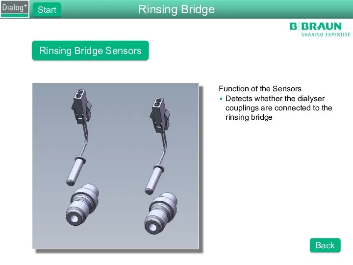
Rinsing Bridge Sensors
Function of the Sensors
Detects whether the dialyser couplings are
Rinsing Bridge Sensors
Function of the Sensors
Detects whether the dialyser couplings are
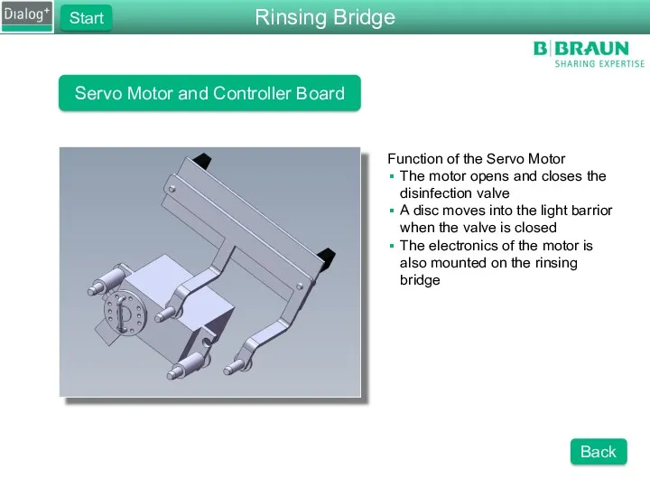
Servo Motor and Controller Board
Function of the Servo Motor
The motor
Servo Motor and Controller Board
Function of the Servo Motor
The motor

FPE Motor Cover
Functions of the FPE Motor Cover
Protects the moving
FPE Motor Cover
Functions of the FPE Motor Cover
Protects the moving
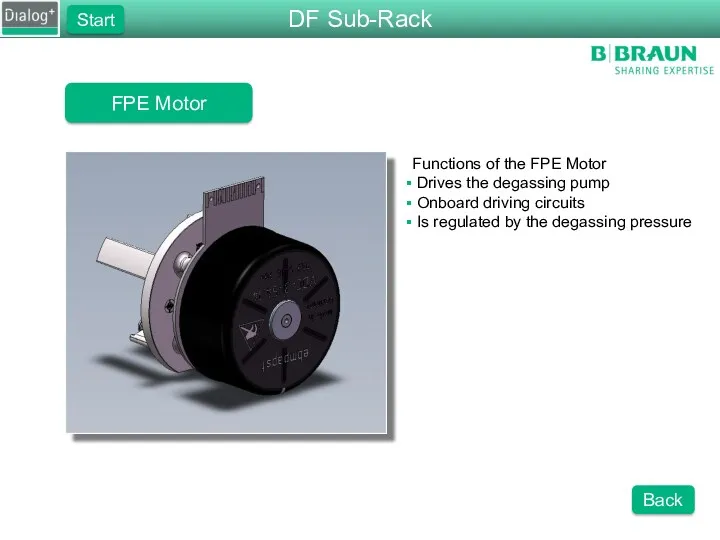
FPE Motor
Functions of the FPE Motor
Drives the degassing pump
Onboard
FPE Motor
Functions of the FPE Motor
Drives the degassing pump
Onboard

FPA Motor
Functions of the FPA Motor
Drives the degassing pump
Onboard
FPA Motor
Functions of the FPA Motor
Drives the degassing pump
Onboard
FPA Motor Cover
Functions of the FPA Motor Cover
Protects the moving
FPA Motor Cover
Functions of the FPA Motor Cover
Protects the moving
Hydraulic Flow Diagram
Please choose a part of the flow diagram that
Hydraulic Flow Diagram
Please choose a part of the flow diagram that
FPE Adapter Block
Functions of the FPE Adaptor Block
Mounts the FPE
Absorbs vibrations
FPE Adapter Block
Functions of the FPE Adaptor Block
Mounts the FPE
Absorbs vibrations
FPE, Micropump Vers. 2
Functions of the FPE Pump
Creates a positive pressure
FPE, Micropump Vers. 2
Functions of the FPE Pump
Creates a positive pressure
FPA, Micrpump Vers. 1
Functions of the FPA Pump
Creates a positive pressure
FPA, Micrpump Vers. 1
Functions of the FPA Pump
Creates a positive pressure
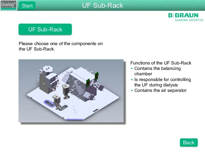
UF Sub-Rack
Please choose one of the components on the UF Sub-Rack.
Functions
UF Sub-Rack
Please choose one of the components on the UF Sub-Rack.
Functions
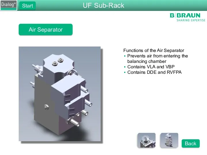
Air Separator
Functions of the Air Separator
Prevents air from entering the balancing
Air Separator
Functions of the Air Separator
Prevents air from entering the balancing
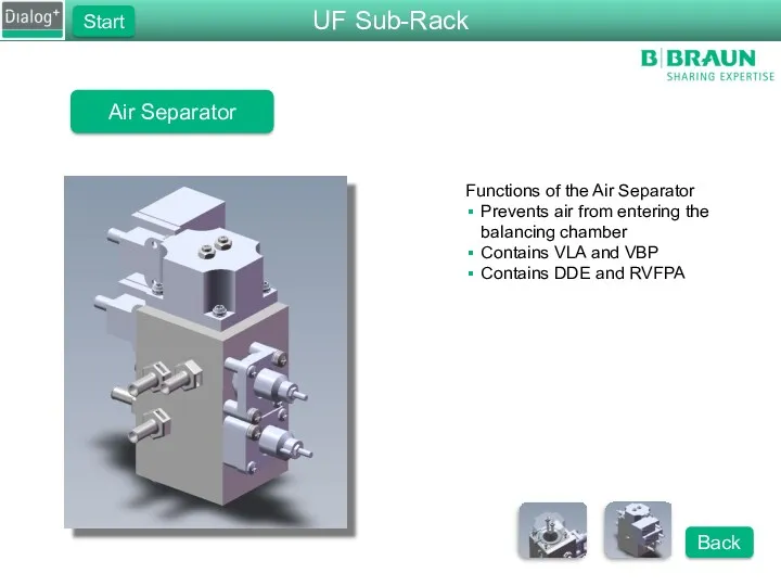
Air Separator
Functions of the Air Separator
Prevents air from entering the balancing
Air Separator
Functions of the Air Separator
Prevents air from entering the balancing
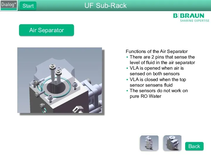
Air Separator
Functions of the Air Separator
There are 2 pins that sense
Air Separator
Functions of the Air Separator
There are 2 pins that sense
Balance Chamber
Functions of the Balance Chamber
Consists of 2 chambers, with 8
Balance Chamber
Functions of the Balance Chamber
Consists of 2 chambers, with 8
Balance Chamber Membrane
Functions of the Balance Chamber Membrane
Separates fresh and used
Balance Chamber Membrane
Functions of the Balance Chamber Membrane
Separates fresh and used
Membrane Position Sensor
Functions of the membrane position sensor
Measures the position of
Membrane Position Sensor
Functions of the membrane position sensor
Measures the position of
Water Sub-Rack
Please choose one of the component groups of the water
Water Sub-Rack
Please choose one of the component groups of the water
Water Block
Please choose one of the components on the water block
Water Block
Please choose one of the components on the water block
Upline Tank
Please choose one of the components in the upline tank.
Components
Upline Tank
Please choose one of the components in the upline tank.
Components
Degassing Pump, Micropump Vers. 2
Please choose a part of the degassing
Degassing Pump, Micropump Vers. 2
Please choose a part of the degassing
DF Sub-Rack
Please choose one of the components on the DF Sub-Rack.
Functions
DF Sub-Rack
Please choose one of the components on the DF Sub-Rack.
Functions
Inlet Flow Pump
Please select a part of the FPE that
Inlet Flow Pump
Please select a part of the FPE that
Outlet Flow Pump
Please select a part of the FPA that you
Outlet Flow Pump
Please select a part of the FPA that you
DF Block
Please select one of the components on the DF block.
Functions
DF Block
Please select one of the components on the DF block.
Functions
DF Block
Please select one of the components on the DF block.
Functions
DF Block
Please select one of the components on the DF block.
Functions
DF Block
Please select one of the components on the DF block.
Functions
DF Block
Please select one of the components on the DF block.
Functions
Conductivity Sensors
Functions of the conductivity cells
ENDLF measures the final conductivity
ENDLF_S supervises
Conductivity Sensors
Functions of the conductivity cells
ENDLF measures the final conductivity
ENDLF_S supervises
Disinfection Valve
Please select a part of the disinfection valve.
Functions of the
Disinfection Valve
Please select a part of the disinfection valve.
Functions of the
Rinsing Bridge
Please choose one of the components on the rinsing bridge.
Functions
Rinsing Bridge
Please choose one of the components on the rinsing bridge.
Functions
UF Sub-Rack
Please choose one of the components on the UF Sub-Rack.
Functions
UF Sub-Rack
Please choose one of the components on the UF Sub-Rack.
Functions
Temperature Regulation
The temperature regulation is done by the following components
TSE
TSHE
TSD
TSDE
Water Sub-Rack
Start
Back
Next
Temperature Regulation
The temperature regulation is done by the following components
TSE
TSHE
TSD
TSDE
Water Sub-Rack
Start
Back
Next
Temperature Regulation
The first temperature regulation is done with TSE. This sensor
Temperature Regulation
The first temperature regulation is done with TSE. This sensor
Temperature Regulation
Once the temperature is stable at TSE, the controller starts
Temperature Regulation
Once the temperature is stable at TSE, the controller starts
Temperature Regulation
After approx. 10 minutes the machine will use TSDE to
Temperature Regulation
After approx. 10 minutes the machine will use TSDE to
Temperature Regulation
If the machine is switched to bypass, TSD will take
Temperature Regulation
If the machine is switched to bypass, TSD will take
Temperature Regulation
At all times during the therapy TSD-S is active to
Temperature Regulation
At all times during the therapy TSD-S is active to
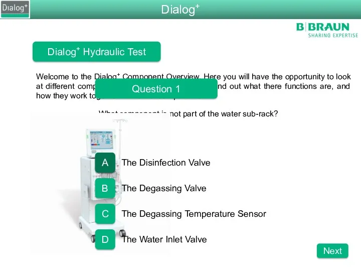
What compenent is not part of the water sub-rack?
Welcome to the
What compenent is not part of the water sub-rack?
Welcome to the
Dialog+ Hydraulic Test
Question 2
How many temperature sensors are in the machine?
4
5
6
7
Dialog+
A
B
D
Next
C
C
Dialog+ Hydraulic Test
Question 2
How many temperature sensors are in the machine?
4
5
6
7
Dialog+
A
B
D
Next
C
C
Dialog+ Hydraulic Test
Question 3
What is the status of the degassing valve
Dialog+ Hydraulic Test
Question 3
What is the status of the degassing valve
Dialog+ Hydraulic Test
Question 4
Which pump is responsable for pumping fresh dialysate
Dialog+ Hydraulic Test
Question 4
Which pump is responsable for pumping fresh dialysate
Dialog+ Hydraulic Test
Question 5
What is the pressure of RVDA set to
Dialog+ Hydraulic Test
Question 5
What is the pressure of RVDA set to

Dialog+ Hydraulic Test
Question 6
Wat is the approx. speed for EP, FPE,
Dialog+ Hydraulic Test
Question 6
Wat is the approx. speed for EP, FPE,
Dialog+ Hydraulic Test
Test Completed
Press the Show Results button to find out
Dialog+ Hydraulic Test
Test Completed
Press the Show Results button to find out
Chemical Thermal Disinfections
All pumps are running
3 min rinsing and heating to
Chemical Thermal Disinfections
All pumps are running
3 min rinsing and heating to
Chemical Thermal Disinfections
All pumps are running
Minimum disinfection time, above minimum Temp
Dialog+
Next
Chemical Thermal Disinfections
All pumps are running
Minimum disinfection time, above minimum Temp
Dialog+
Next
Chemical Thermal Disinfections
VBICP Test phase 1
Negative Pressure with VVB and VBICP
Chemical Thermal Disinfections
VBICP Test phase 1
Negative Pressure with VVB and VBICP
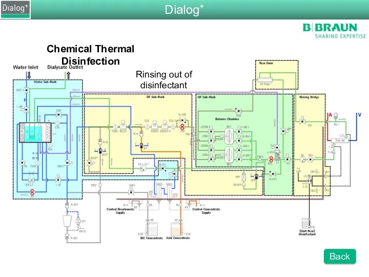
Chemical Thermal Disinfection
Rinsing out of disinfectant
Dialog+
Back
Chemical Thermal Disinfection
Rinsing out of disinfectant
Dialog+
Back
 С Новым Годом
 Презентация Microsoft PowerPoint
 Арктика. Природная зона арктических пустынь
 Анализ рынка рабочей силы. Оценка перспектив пополнения предприятия кадрами
 Матрешка
 Александр Николаевич Островский
 Базовые методы и понятия программирования
 Горные ландшафты и туризм
 Депонирование и мобилизация жиров
 Личные местоимения
 Михаил Петрович Лазарев и его географические открытия
 презентация на семинар
 Планируемые результаты обучения обществознанию в основной школе в соответствии с требованиями ФГОС
 Правовые семьи: понятие, классификация и правовой стиль
 презентация к уроку
 Швейная отрасль УИС
 Книжный магазин
 Самара вчера, сегодня, завтра
 Умная теплица
 Фрэнсис Бэкон как основоположник эмпиризма
 Формы расселения населения
 Квантавыя ўласцівасці выпраменьвання
 Синтаксичні особливості українського ділового мовлення
 20231001_seminar_08.12.2022
 Принципы и методы обучения ИЯ
 Спортивный бальный танец
 Урок-презентация Петроград-колыбель Октября
 Дидактическая игра Народные промыслы