- Fuel system

Содержание
- 2. The A320 fuel system is very much like a conventional jet aircraft fuel system. It has
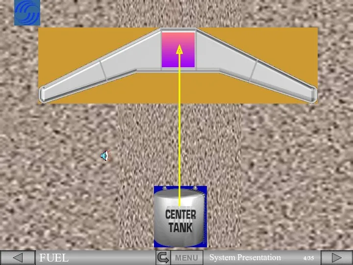
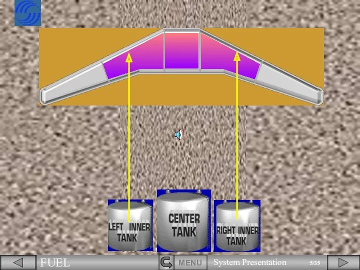
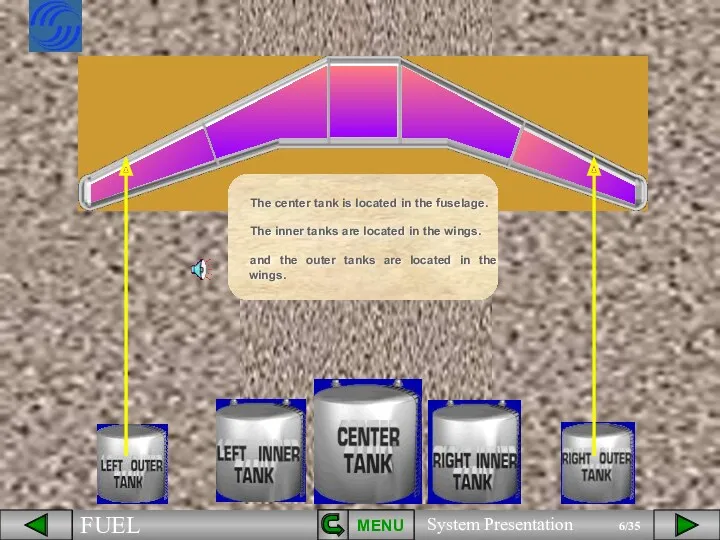
- 6. MENU The center tank is located in the fuselage. The inner tanks are located in the
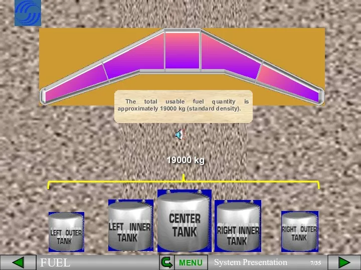
- 7. MENU The total usable fuel quantity is approximately 19000 kg (standard density). 19000 kg
- 8. FUEL PUMPS
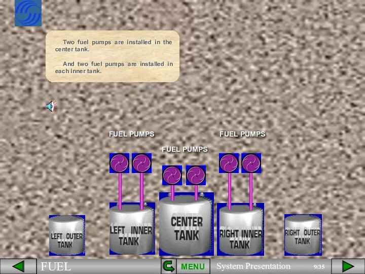
- 9. FUEL PUMPS FUEL PUMPS MENU Two fuel pumps are installed in the center tank. And two
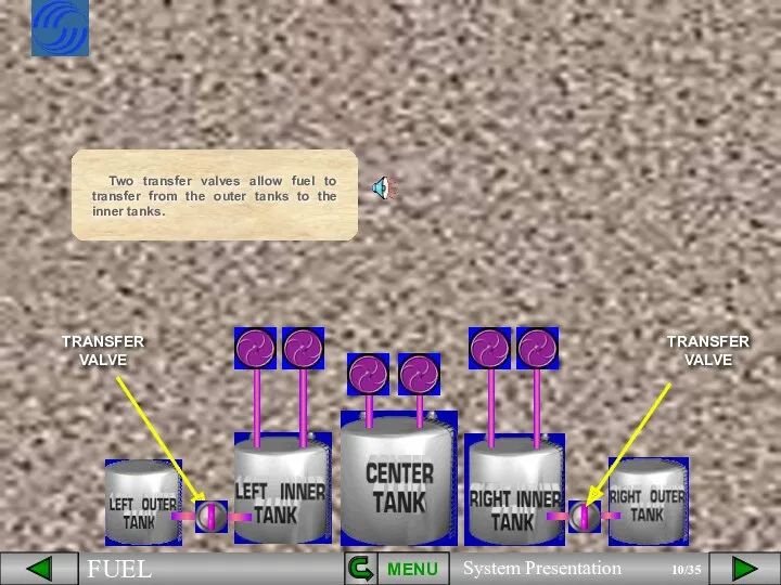
- 10. TRANSFER VALVE TRANSFER VALVE Two transfer valves allow fuel to transfer from the outer tanks to
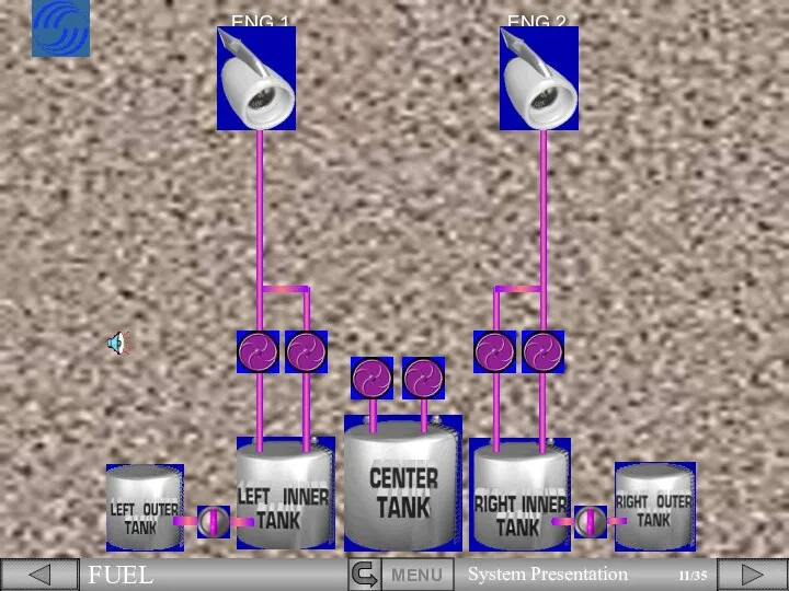
- 11. ENG 2 ENG 1
- 12. Each inner tank feeds its respective engine. Two engine Low Pressure valves are installed to cut
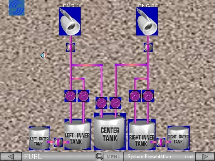
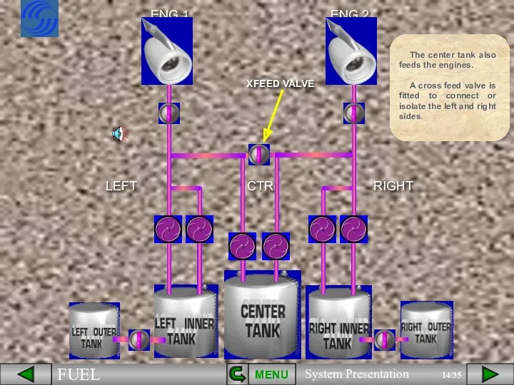
- 14. XFEED VALVE MENU The center tank also feeds the engines. A cross feed valve is fitted
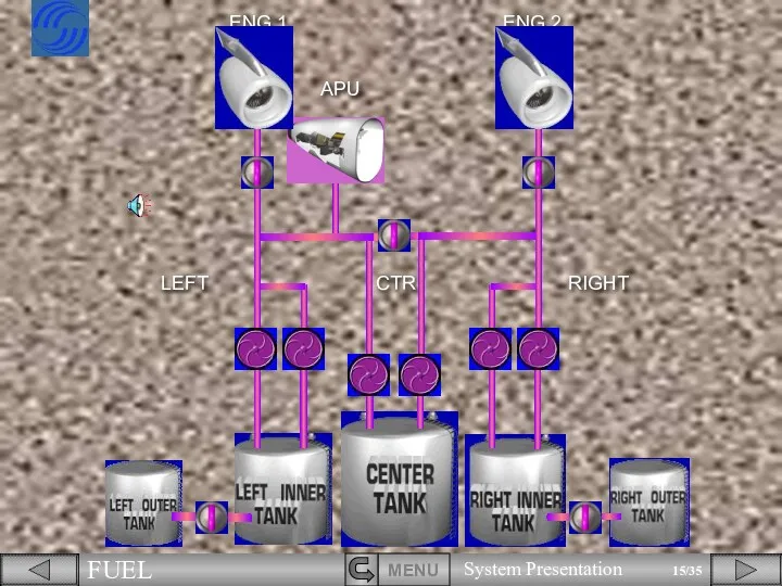
- 15. APU
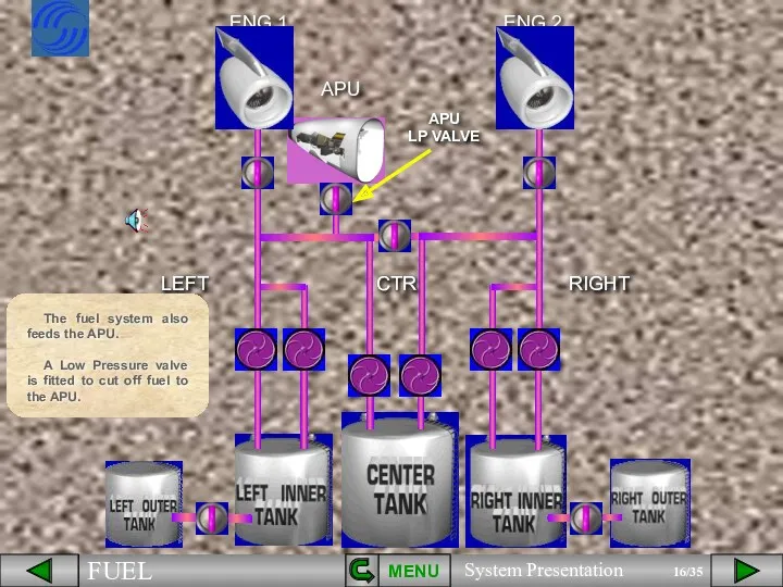
- 16. CTR LEFT RIGHT The fuel system also feeds the APU. A Low Pressure valve is fitted
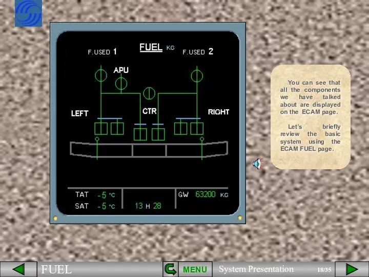
- 17. This represents the basic fuel system. We will now see how this information is presented to
- 18. You can see that all the components we have talked about are displayed on the ECAM
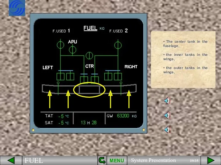
- 19. MENU The center tank in the fuselage, the inner tanks in the wings, the outer tanks
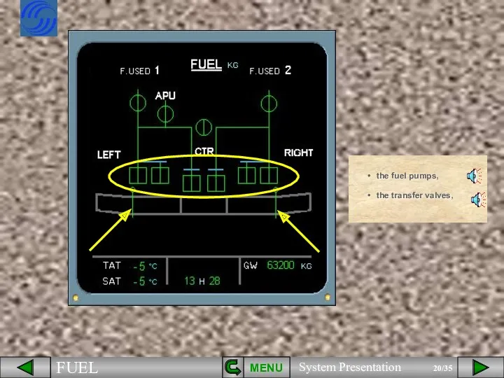
- 20. MENU the fuel pumps, the transfer valves,
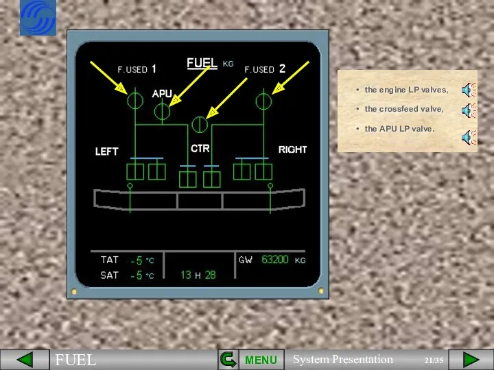
- 21. MENU the engine LP valves, the crossfeed valve, the APU LP valve.
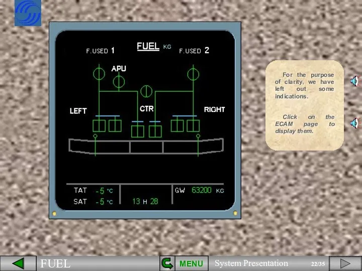
- 22. For the purpose of clarity, we have left out some indications. MENU Click on the ECAM
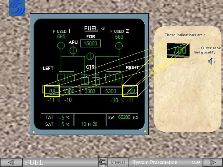
- 23. These indications are : - Outer tank fuel quantity,
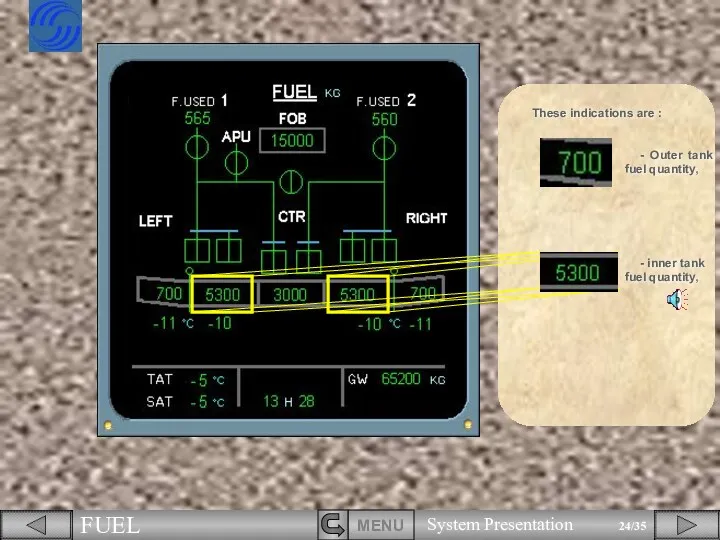
- 24. These indications are : - inner tank fuel quantity, - Outer tank fuel quantity,
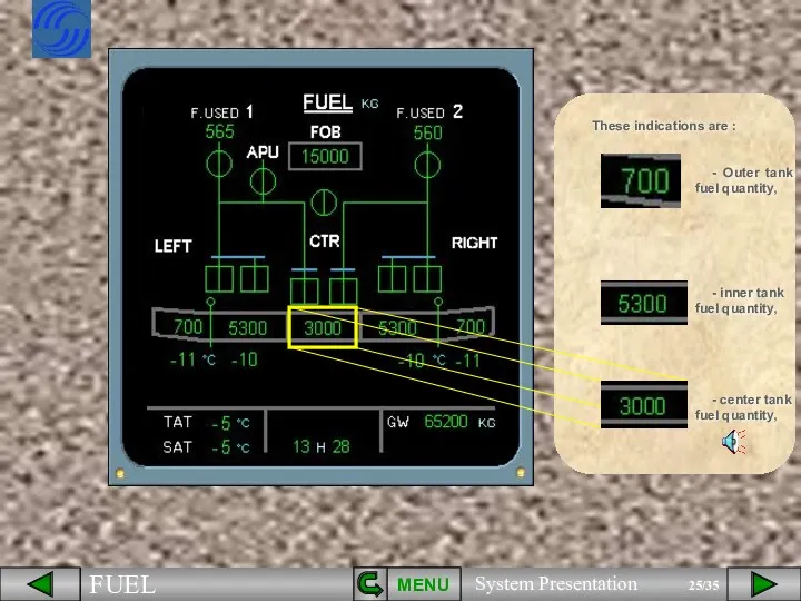
- 25. These indications are : - inner tank fuel quantity, MENU - center tank fuel quantity, -
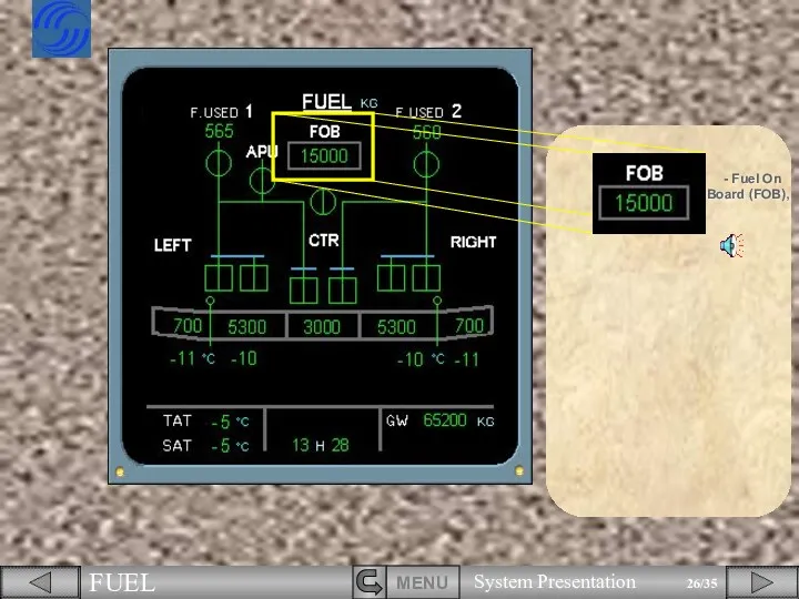
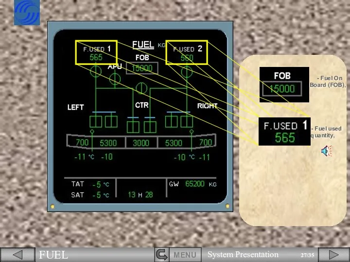
- 26. - Fuel On Board (FOB),
- 27. - Fuel On Board (FOB), - Fuel used quantity,
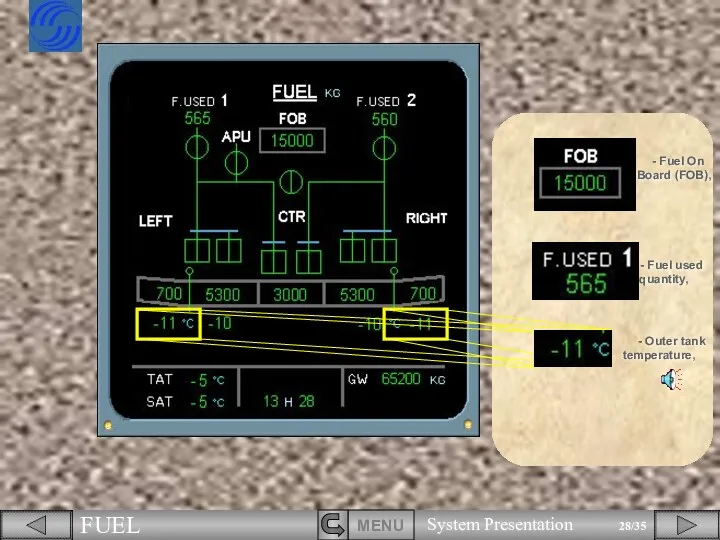
- 28. - Fuel used quantity, - Fuel On Board (FOB), - Outer tank temperature,
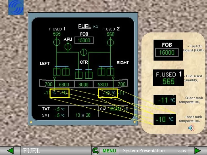
- 29. - Fuel used quantity, - Fuel On Board (FOB), MENU - Outer tank temperature, - Inner
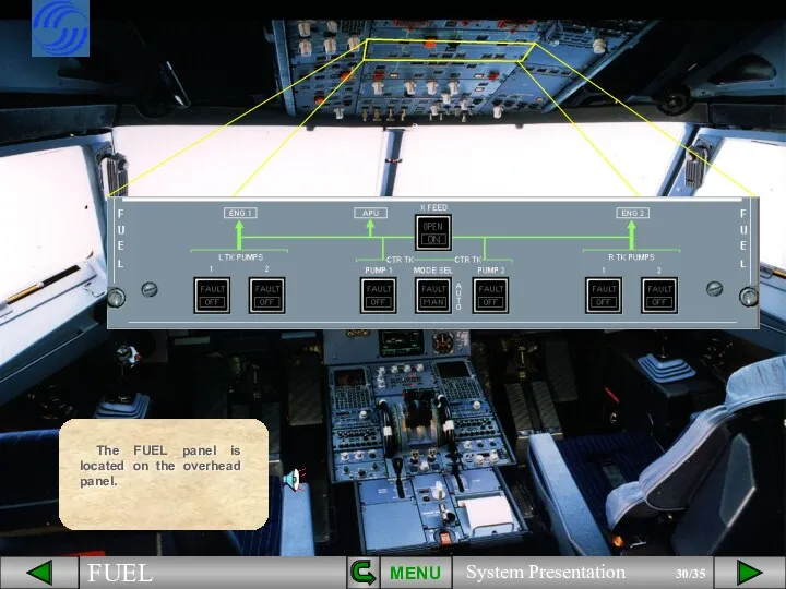
- 30. The FUEL panel is located on the overhead panel. MENU
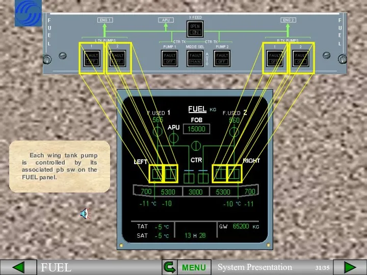
- 31. Each wing tank pump is controlled by its associated pb sw on the FUEL panel. MENU
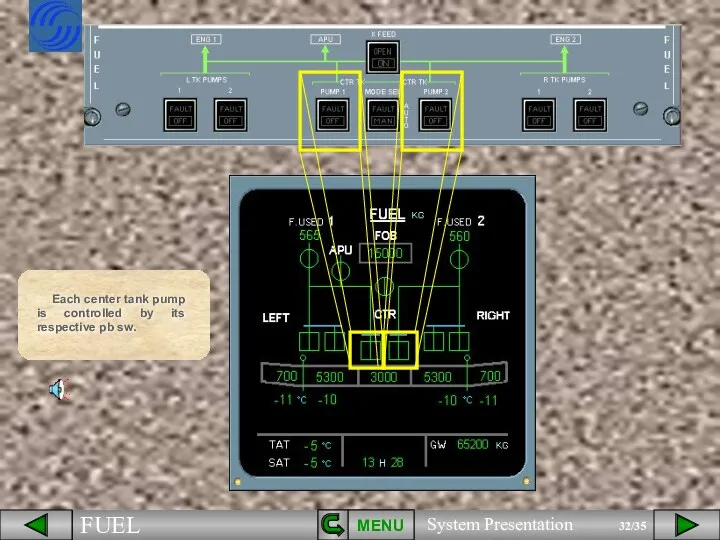
- 32. Each center tank pump is controlled by its respective pb sw. MENU
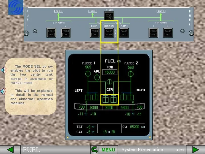
- 33. The MODE SEL pb sw enables the pilot to run the two center tank pumps in
- 34. The X FEED pb sw enables the pilot to connect or isolate the left and right
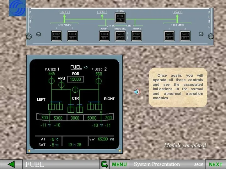
- 35. MENU NEXT Module completed Once again, you will operate all these controls and see the associated
- 37. Скачать презентацию
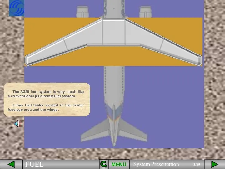
The A320 fuel system is very much like a conventional jet
The A320 fuel system is very much like a conventional jet
MENU
The center tank is located in the fuselage.
The inner tanks are
MENU
The center tank is located in the fuselage.
The inner tanks are
MENU
The total usable fuel quantity is approximately 19000 kg (standard density).
19000
MENU
The total usable fuel quantity is approximately 19000 kg (standard density).
19000
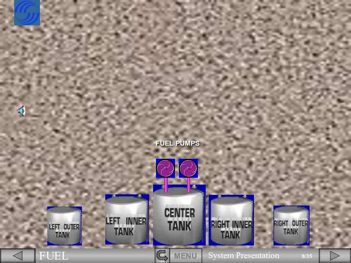
FUEL PUMPS
FUEL PUMPS
FUEL PUMPS
FUEL PUMPS
MENU
Two fuel pumps are installed in the center tank.
And
FUEL PUMPS
FUEL PUMPS
MENU
Two fuel pumps are installed in the center tank.
And
TRANSFER
VALVE
TRANSFER
VALVE
Two transfer valves allow fuel to transfer from the outer tanks
TRANSFER
VALVE
TRANSFER
VALVE
Two transfer valves allow fuel to transfer from the outer tanks
ENG 2
ENG 1
ENG 2
ENG 1
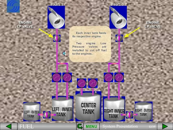
Each inner tank feeds its respective engine.
Two engine Low Pressure valves
Each inner tank feeds its respective engine.
Two engine Low Pressure valves
XFEED VALVE
MENU
The center tank also feeds the engines.
A cross feed valve
XFEED VALVE
MENU
The center tank also feeds the engines.
A cross feed valve
APU
APU
CTR
LEFT
RIGHT
The fuel system also feeds the APU.
A Low Pressure valve is
CTR
LEFT
RIGHT
The fuel system also feeds the APU.
A Low Pressure valve is
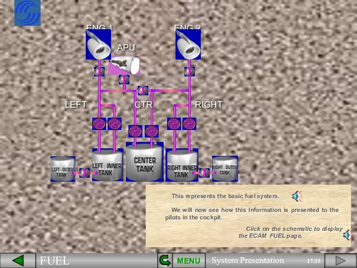
This represents the basic fuel system.
We will now see how this
This represents the basic fuel system.
We will now see how this
You can see that all the components we have talked about
You can see that all the components we have talked about
MENU
The center tank in the fuselage,
the inner tanks in
MENU
The center tank in the fuselage,
the inner tanks in
MENU
the fuel pumps,
the transfer valves,
MENU
the fuel pumps,
the transfer valves,
MENU
the engine LP valves,
the crossfeed valve,
the APU LP valve.
MENU
the engine LP valves,
the crossfeed valve,
the APU LP valve.
For the purpose of clarity, we have left out some indications.
MENU
Click
For the purpose of clarity, we have left out some indications.
MENU
Click
These indications are :
- Outer tank fuel quantity,
These indications are :
- Outer tank fuel quantity,
These indications are :
- inner tank fuel quantity,
- Outer tank
These indications are :
- inner tank fuel quantity,
- Outer tank
These indications are :
- inner tank fuel quantity,
MENU
- center tank
These indications are :
- inner tank fuel quantity,
MENU
- center tank
- Fuel On Board (FOB),
- Fuel On Board (FOB),
- Fuel On Board (FOB),
- Fuel used quantity,
- Fuel On Board (FOB),
- Fuel used quantity,
- Fuel used quantity,
- Fuel On Board (FOB),
- Outer
- Fuel used quantity,
- Fuel On Board (FOB),
- Outer
- Fuel used quantity,
- Fuel On Board (FOB),
MENU
- Outer
- Fuel used quantity,
- Fuel On Board (FOB),
MENU
- Outer
The FUEL panel is located on the overhead panel.
MENU
The FUEL panel is located on the overhead panel.
MENU
Each wing tank pump is controlled by its associated pb sw
Each wing tank pump is controlled by its associated pb sw
Each center tank pump is controlled by its respective pb sw.
MENU
Each center tank pump is controlled by its respective pb sw.
MENU
The MODE SEL pb sw enables the pilot to run the
The MODE SEL pb sw enables the pilot to run the
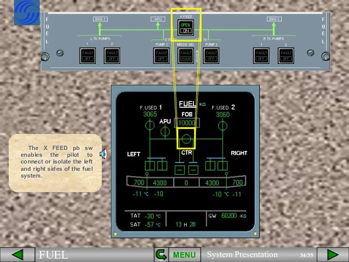
The X FEED pb sw enables the pilot to connect or
The X FEED pb sw enables the pilot to connect or
MENU
NEXT
Module completed
Once again, you will operate all these controls and see
MENU
NEXT
Module completed
Once again, you will operate all these controls and see
 Обследование звукослоговой структуры слов с использованием ИКТ
 Кіномистецтво
 Проект на тему Человек, которым я горжусь. Владимир Иванович Даль 1801-1872
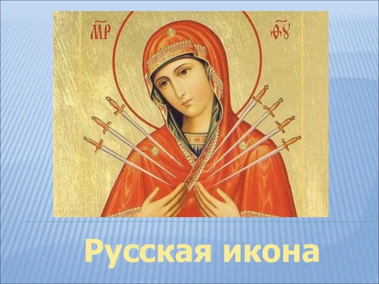 Иконопись. Русская икона
 День недели…
 Эстетикалық стоматология үшін оптикалық жүйенің маңызы
 Презентация Интегративный подход в организации экспериментальной деятельности младших дошкольников
 Автомобильные грузовые транспортные средства
 Военно-мостовая подготовка. Итоговый тест
 ЧПУ станоктары
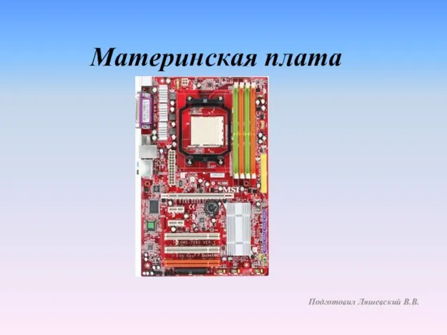 Материнская плата
 Презентация к классному часу Наши права и обязанности
 Межзвёздная среда: Газ и пыль
 мультик
 класс
класс русский 08.02
 Случаи вычитания 16-
 Клятвы на новый год
 Контроль качества строительно-монтажных работ
 Проблематика романа М. Булгакова Белая гвардия
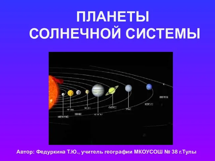 Разработка урока Планеты Солнечной системы.
 Сотворение человека. Православная антропология
 The degrees of comparison of adjectives
 Проектная деятельность обучающихся. Проект по теме Сколько весит здоровье ученика?
 20191208_kraevedcheskoe_kazino_loyma_i_eyo_okrestnosti
 Советский Союз в 1950--1991 годах
 Испытание № 6. Бутерброд NETWORKING
 Загадки про игрушки (ранний возраст)