- Group A-Introduction

Содержание
- 2. TRAINING USE ONLY ATA 01 - INTRODUCTION Introduction A-02 DA40 Series (Austro Engine) Issue: July 2011
- 3. TRAINING USE ONLY Revision Service The manufacturer provides a revision service for the Airplane Maintenance Manual.
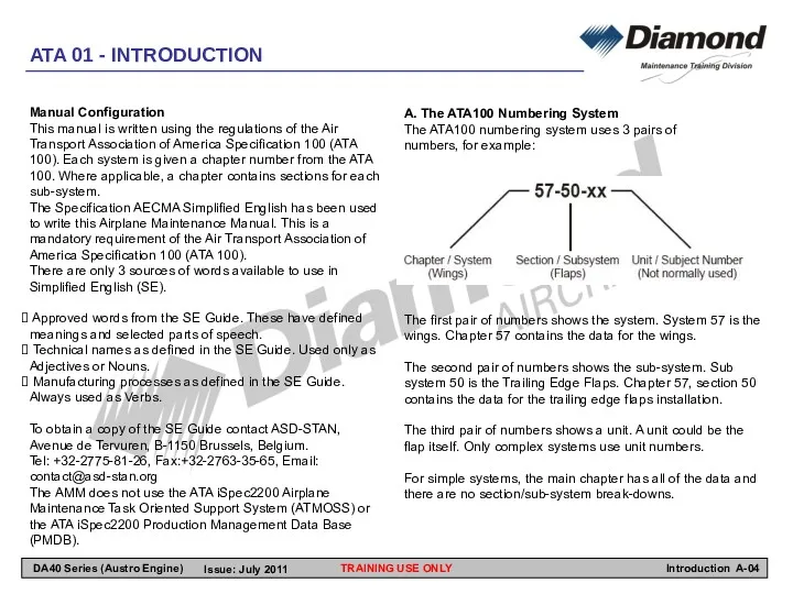
- 4. TRAINING USE ONLY A. The ATA100 Numbering System The ATA100 numbering system uses 3 pairs of
- 5. B. Groups of Chapters The chapters are put together in these groups: Group A Introduction Chapters
- 6. Group E - Propeller Chapter 61 contains the maintenance procedures for the propeller. Refer to the
- 7. ATA 02 – MANUAL SYSTEM TRAINING USE ONLY Introduction A-07 DA40 Series (Austro Engine) Issue: July
- 8. Organization and Handling of Manuals General For data about a system, look in the list of
- 9. Service Instructions A Service Instruction tells the operator about permitted installations or additional equipment. It also
- 10. AC Alternating Current ACL Anti-Collision Light ADC Air Data Computer ADF Automatic Direction Finder AH Artificial
- 11. LCD Liquid Crystal Display LDG Landing LED Light Emitting Diode LH Left Hand LOC Localizer LOEP
- 13. Скачать презентацию
TRAINING USE ONLY
ATA 01 - INTRODUCTION
Introduction A-02
DA40 Series (Austro Engine)
Issue: July
TRAINING USE ONLY
ATA 01 - INTRODUCTION
Introduction A-02
DA40 Series (Austro Engine)
Issue: July
TRAINING USE ONLY
Revision Service
The manufacturer provides a revision service for the
TRAINING USE ONLY
Revision Service
The manufacturer provides a revision service for the
TRAINING USE ONLY
A. The ATA100 Numbering System
The ATA100 numbering system uses
TRAINING USE ONLY
A. The ATA100 Numbering System
The ATA100 numbering system uses
B. Groups of Chapters
The chapters are put together in these groups:
Group
B. Groups of Chapters
The chapters are put together in these groups:
Group
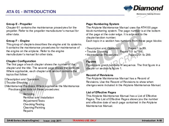
Group E - Propeller
Chapter 61 contains the maintenance procedures for the
Group E - Propeller
Chapter 61 contains the maintenance procedures for the
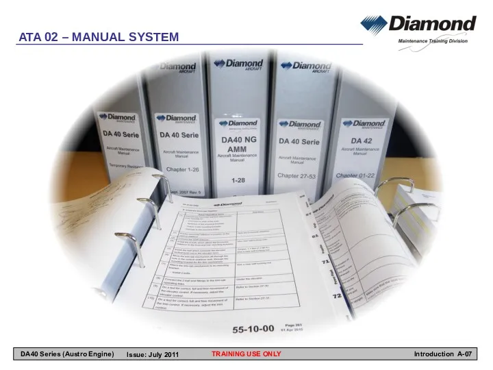
ATA 02 – MANUAL SYSTEM
TRAINING USE ONLY
Introduction A-07
DA40 Series (Austro Engine)
Issue:
ATA 02 – MANUAL SYSTEM
TRAINING USE ONLY
Introduction A-07
DA40 Series (Austro Engine)
Issue:
Organization and Handling of Manuals
General
For data about a system, look in
Organization and Handling of Manuals
General
For data about a system, look in
Service Instructions
A Service Instruction tells the operator about permitted installations or
Service Instructions
A Service Instruction tells the operator about permitted installations or
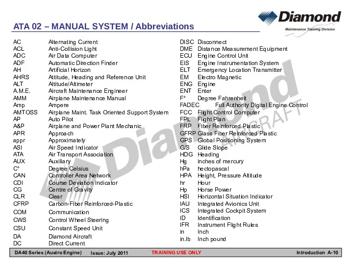
AC Alternating Current
ACL Anti-Collision Light
ADC Air Data Computer
ADF Automatic Direction Finder
AH Artificial Horizon
AHRS Attitude, Heading and Reference
AC Alternating Current
ACL Anti-Collision Light
ADC Air Data Computer
ADF Automatic Direction Finder
AH Artificial Horizon
AHRS Attitude, Heading and Reference
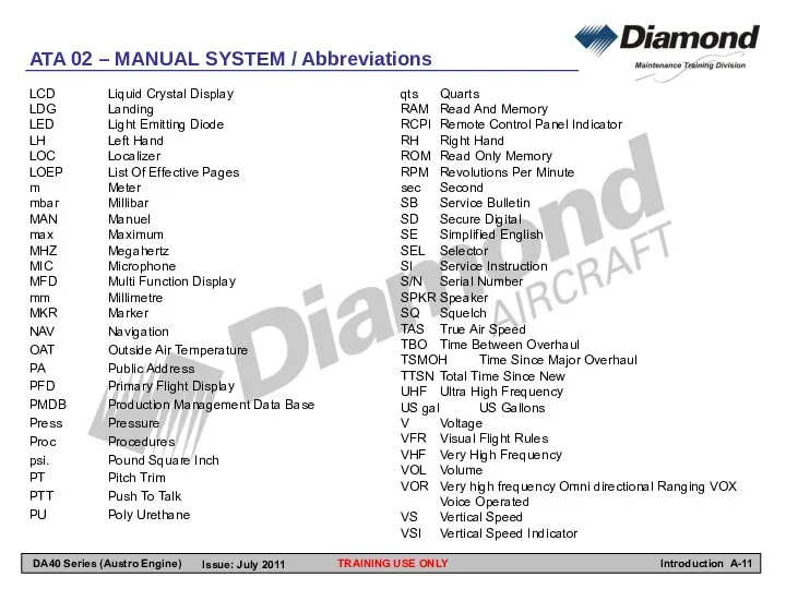
LCD Liquid Crystal Display
LDG Landing
LED Light Emitting Diode
LH Left Hand
LOC Localizer
LOEP List Of Effective Pages
m Meter
mbar Millibar
MAN Manuel
max Maximum
MHZ Megahertz
MIC Microphone
MFD Multi
LCD Liquid Crystal Display
LDG Landing
LED Light Emitting Diode
LH Left Hand
LOC Localizer
LOEP List Of Effective Pages
m Meter
mbar Millibar
MAN Manuel
max Maximum
MHZ Megahertz
MIC Microphone
MFD Multi
 Модернизация технической базы и ремонтных мастерских сельскохозяйственных предприятий и других агропромышленных структур
 Русь в середине XI - начале XII века
 Путешествие в страну вежливоти и доброты
 Технология проведения мастер-класса.
 Аттестационная работа
 Технические средства телекоммуникационных технологий
 Типы и этапы урока в специальном (коррекционном) классе VIII вида
 Физиократия. Экономическая таблица. Основные выводы
 КПД тепловых двигателей
 Опасные природные явления Сахалинской области
 20230816_1-6_klass_-_kopiya
 Санитарные требования к проведению уборки. Выбор моющих средств
 Молекулярная биология. Курс лекций
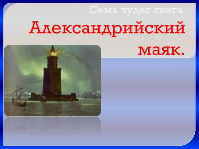 Александрийский маяк
 3. PLANET
 Презентация по рабочей профессииОператор электронного набора иверстки
 Перевёрнутый треугольник (женский тип фигуры)
 Християнство. Історичні передумови виникнення
 Бджільництво
 Leadership
 Мясорубка МИМ-300
 Политическое поведение. Классификация политического поведения
 Четырехугольники. Решение задач
 Презентация к Дню Победы. Диск
 Мы с мамой дома не скучали, по Стрельниковой мы дышали
 Основные функции контроля и оценивания учебных достижений
 Свойства параллельных прямых
 Публичный отчет МБДОУ - детский сад комбинированного вида Лесовичок