- Hermes10 A과제-PJT

Содержание
- 2. Product Introduction Instruction of Function Alignment & Adjustment Disassembly & Reassembly SELF DIAGNOSIS & TROUBLE SHOOTING
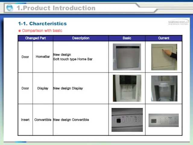
- 3. 1-1. Charcteristics 1.Product Introduction ● Comparison with basic
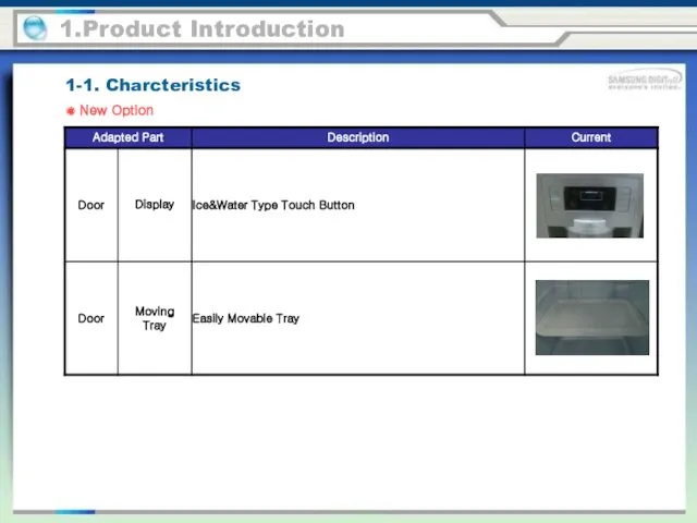
- 4. 1-1. Charcteristics 1.Product Introduction ● New Option
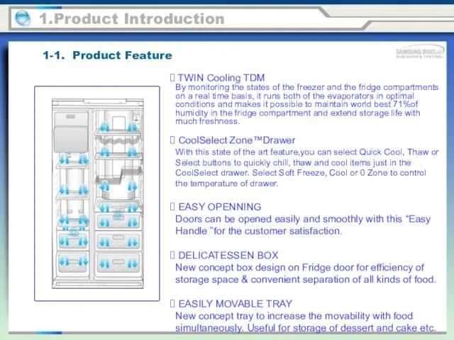
- 5. 1-1. Product Feature 1.Product Introduction TWIN Cooling TDM By monitoring the states of the freezer and
- 6. 1-2. Comparison with competitor 1.Product Specification
- 7. 1-2. Comparison with competitor 1.Product Specification
- 8. 1-3. Parts Name (RSJ1 Series) 1.Product Introduction Ice Chute Door Bin Coolselect Zone Drawer (optional) Drawer
- 9. 1-3. Parts Name (RSH1 Series) 1.Product Introduction Ice Chute Door Bin Coolselect Zone Drawer (optional) Drawer
- 10. 1-4. Specification (RSH5 Series) 1.Product Introduction Components for Freezer
- 11. 1-4. Specification (RSH5 Series) 1.Product Introduction Components for Freezer
- 12. 1-4. Specification (RSH5*** Series) 1.Product Introduction Components for Freezer
- 13. 1-4. Specification (RSH5*** Series) 1.Product Introduction Components for Freezer
- 14. 1.Product Introduction Room Temperature Sensor Components Freezer Refrigerator 1-4. Specification (RSH5*** Series)
- 15. 1.Product Introduction Defrost Related Components Freezer Refrigerator 1-4. Specification (RSH5*** Series)
- 16. 1-5. Product Dimension 1.Product Introduction PRODUCT SIZE
- 17. 1-6. Refrigeration TDM Cycle 1.Product Introduction Compressor SPIRAL-CONDENSER FRIDGE HOT PIPE Dryer 3WAY VALVE Fridge Capillary
- 18. 1-6. Refrigeration HM Cycle 1.Product Introduction Compressor Sub-condenser Hot Pipe Dryer Capillary Tube Refrigerator Evaporator Freezer
- 19. 1-7. Internal cool air circulation path 1.Product Introduction
- 20. 2-1. Control Display 2.Instruction of Function Power Freezer Button Speeds up the time needed to freeze
- 21. Filter Change Button When you change the filter, press this button for 3 seconds to reset
- 22. Child Lock Button By pressing the Power Cool and the Fridge buttons together, for 3 seconds,
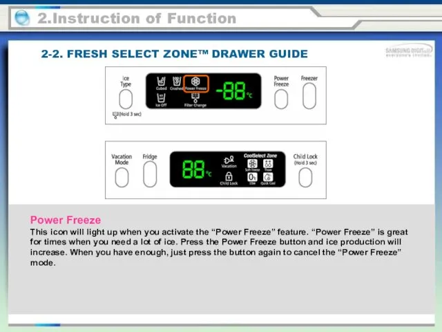
- 23. 2-2. FRESH SELECT ZONE™ DRAWER GUIDE Power Freeze This icon will light up when you activate
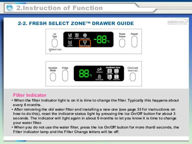
- 24. 2-2. FRESH SELECT ZONE™ DRAWER GUIDE 2.Instruction of Function Filter Indicator When the filter indicator light
- 25. Child Lock This icon will light up when you activate the Child Lock function by pressing
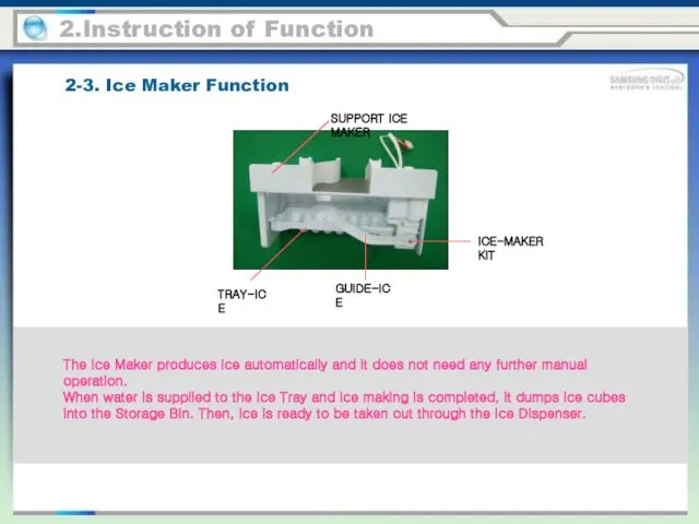
- 26. 2-3. Ice Maker Function 2.Instruction of Function The Ice Maker produces ice automatically and it does
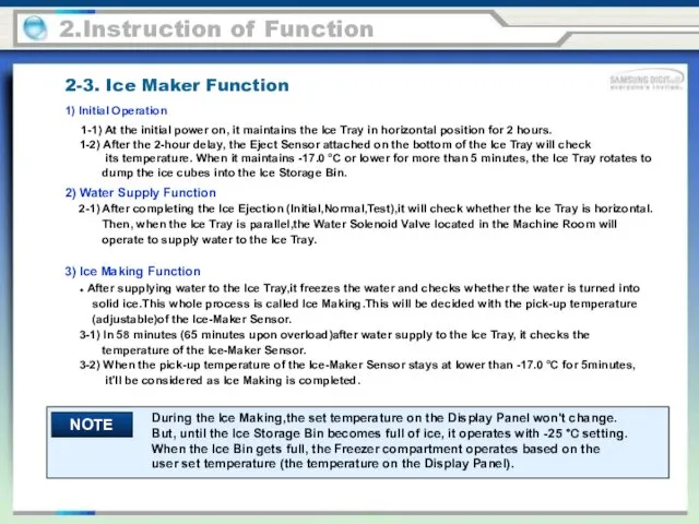
- 27. 2.Instruction of Function 1) Initial Operation 1-1) At the initial power on, it maintains the Ice
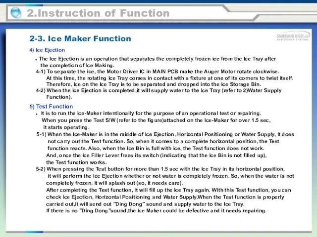
- 28. 2.Instruction of Function 4) Ice Ejection ● The Ice Ejection is an operation that separates the
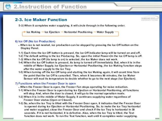
- 29. 2.Instruction of Function 5-3) When it completes water supplying, it will circle through in the following
- 30. 1) Freezer and Fridge defrost will be determined by the total Comp-On time. 2) With the
- 31. Forced Operation / Forced Defrost 3-1. Test Functions 3.Alignment & Adjustment Press the Power Freeze and
- 32. Forced Operation / Forced Defrost 3-1. Test Functions 3.Alignment & Adjustment With the AC Comp model,
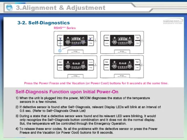
- 33. 3-2. Self-Diagnostics 3.Alignment & Adjustment Self-Diagnosis Function upon Initial Power-On 1) When the unit is plugged
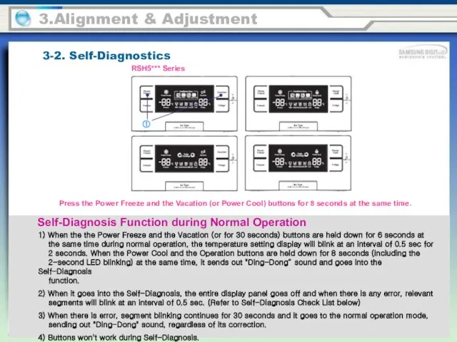
- 34. 3-2. Self-Diagnostics 3.Alignment & Adjustment Self-Diagnosis Function during Normal Operation 1) When the the Power Freeze
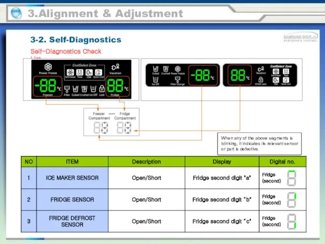
- 35. 3.Alignment & Adjustment 3-2. Self-Diagnostics Self-Diagnostics Check List When any of the above segments is blinking,
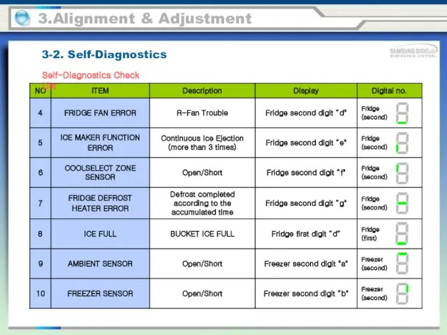
- 36. 3.Alignment & Adjustment 3-2. Self-Diagnostics Self-Diagnostics Check List
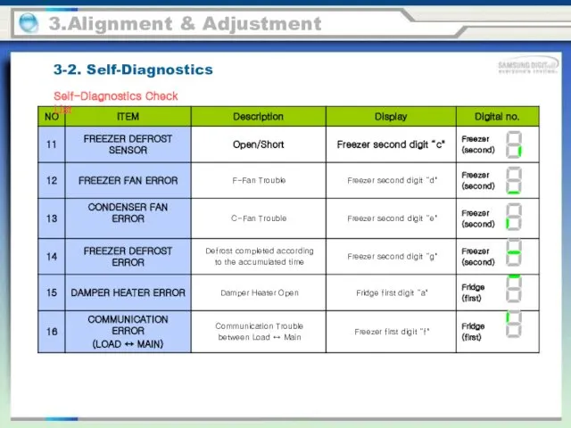
- 37. 3.Alignment & Adjustment 3-2. Self-Diagnostics Self-Diagnostics Check List
- 38. 3.Alignment & Adjustment 3-2. Self-Diagnostics Descriptions of Self-Diagnosis Error Code
- 39. 3.Alignment & Adjustment 3-2. Self-Diagnostics Descriptions of Self-Diagnosis Error Code
- 40. 3.Alignment & Adjustment 3-2. Self-Diagnostics Descriptions of Self-Diagnosis Error Code
- 41. 3-3. Load Status Display 3.Alignment & Adjustment 1) When the Power Freeze and the Vacation (or
- 42. 3.Alignment & Adjustment Load Mode Check List 3-3. Load Status Display
- 43. 3.Alignment & Adjustment Load Mode Check List 3-3. Load Status Display
- 44. 3.Alignment & Adjustment Load Mode Check List 3-3. Load Status Display
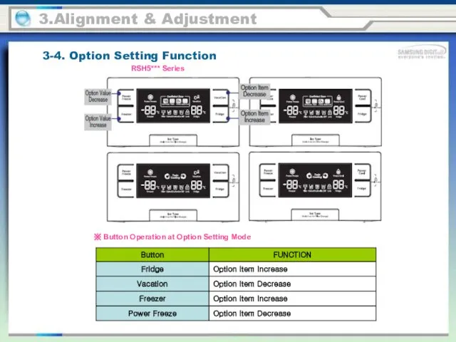
- 45. 3.Alignment & Adjustment 3-4. Option Setting Function Press the Freezer and the Vacation (or Power Cool)
- 46. ※ Button Operation at Option Setting Mode 3.Alignment & Adjustment 3-4. Option Setting Function RSH5*** Series
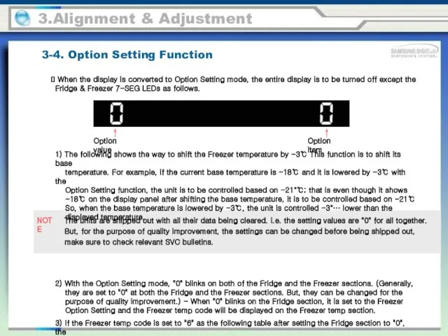
- 47. 3.Alignment & Adjustment 3-4. Option Setting Function When the display is converted to Option Setting mode,
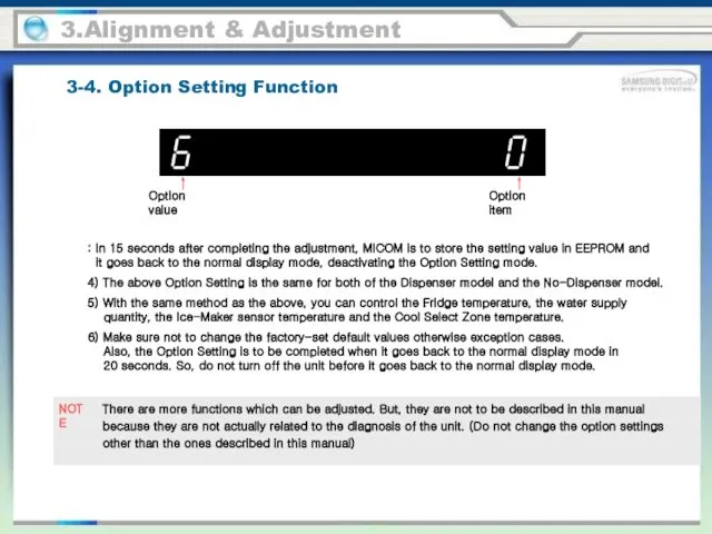
- 48. 3.Alignment & Adjustment 3-4. Option Setting Function There are more functions which can be adjusted. But,
- 49. Ex) Lowering the Freezer default temp by -3℃ 3.Alignment & Adjustment Option value Option item 3-4.
- 50. Ex) Raising the Fridge default temp by +1.5℃ 3.Alignment & Adjustment Option value Option item 3-4.
- 51. Ex) Changing the water supply quantity to 85cc 3.Alignment & Adjustment It controls the water supply
- 52. 3.Alignment & Adjustment It is an option controlling the Ice Ejection Standby time of the Ice-Maker.
- 53. 3.Alignment & Adjustment This option is for sising minimum Comp RPM. As this option is applied,
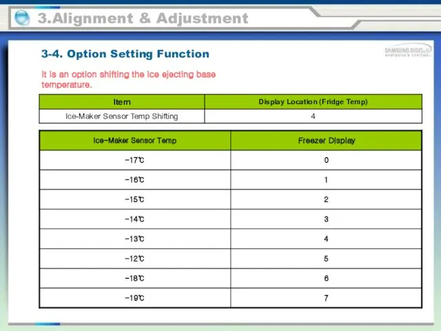
- 54. 3.Alignment & Adjustment It is an option shifting the ice ejecting base temperature. 3-4. Option Setting
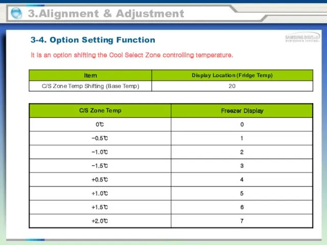
- 55. 3.Alignment & Adjustment It is an option shifting the Cool Select Zone controlling temperature. 3-4. Option
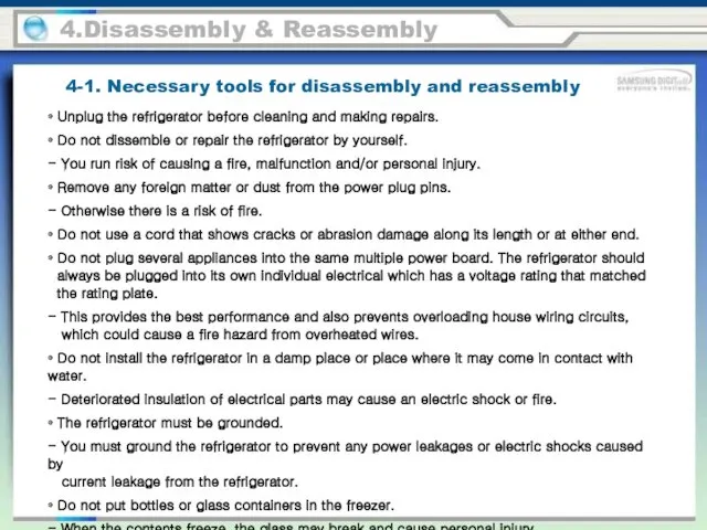
- 56. 4-1. Necessary tools for disassembly and reassembly 4.Disassembly & Reassembly • Unplug the refrigerator before cleaning
- 57. 4-1. Necessary tools for disassembly and reassembly 4.Disassembly & Reassembly
- 58. 4-2. Freezer Display 4.Disassembly & Reassembly
- 59. 4-2. Freezer Display 4.Disassembly & Reassembly
- 60. 4-3. Freezer Micro Switch 4.Disassembly & Reassembly
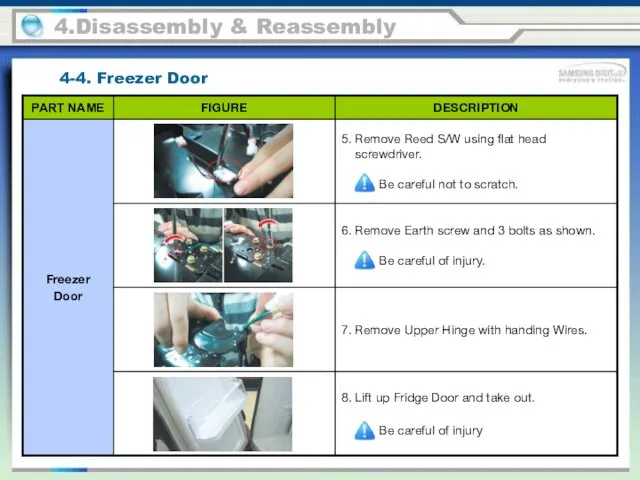
- 61. 4-4. Freezer Door 4.Disassembly & Reassembly
- 62. 4-4. Freezer Door 4.Disassembly & Reassembly
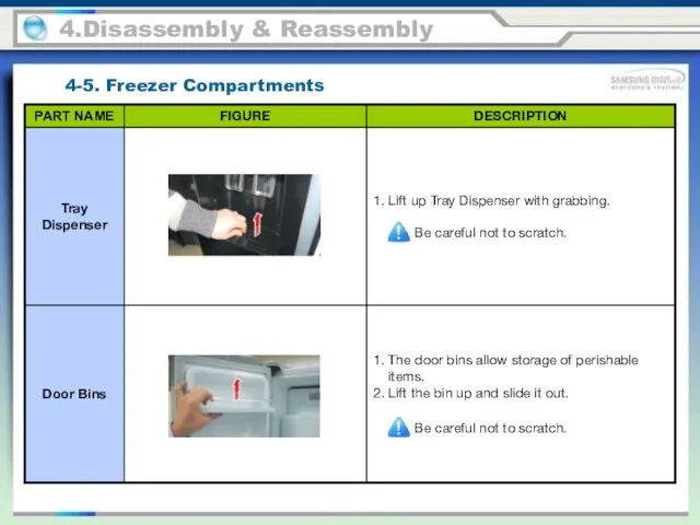
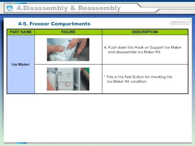
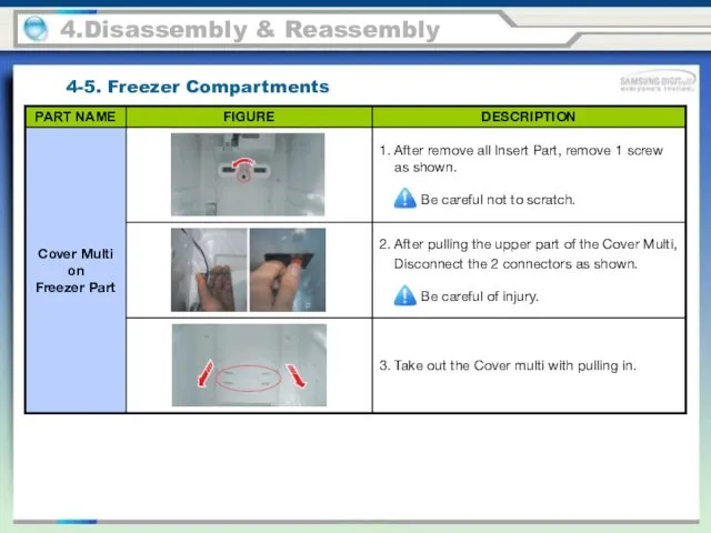
- 63. 4.Disassembly & Reassembly 4-5. Freezer Compartments
- 64. 4.Disassembly & Reassembly 4-5. Freezer Compartments
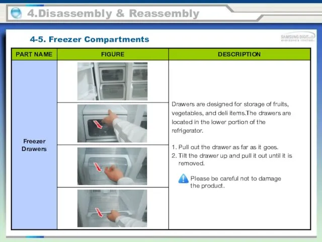
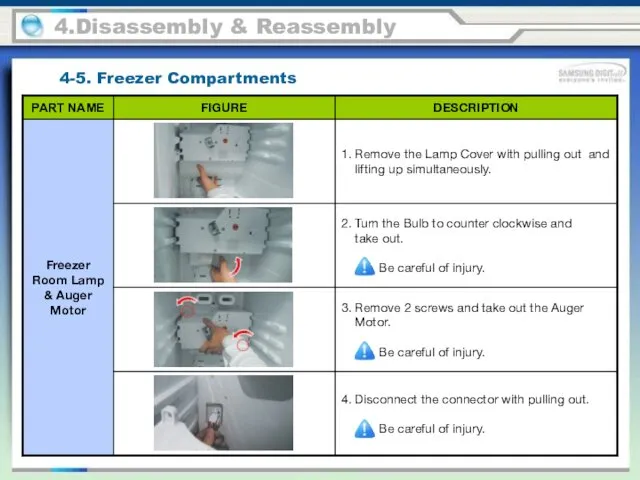
- 65. 4.Disassembly & Reassembly 4-5. Freezer Compartments
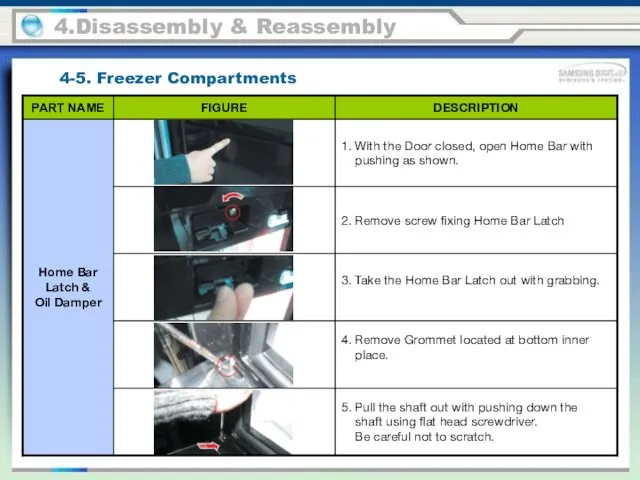
- 66. 4.Disassembly & Reassembly 4-5. Freezer Compartments
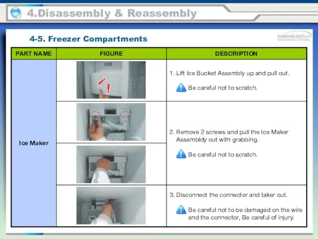
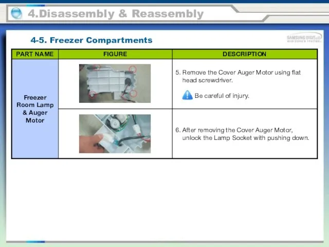
- 67. 4.Disassembly & Reassembly 4-5. Freezer Compartments
- 68. 4.Disassembly & Reassembly 4-5. Freezer Compartments
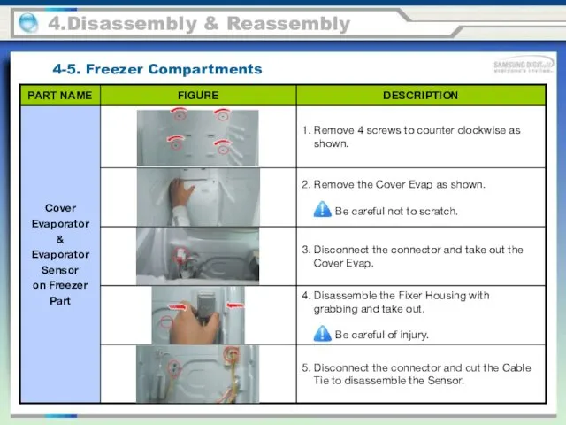
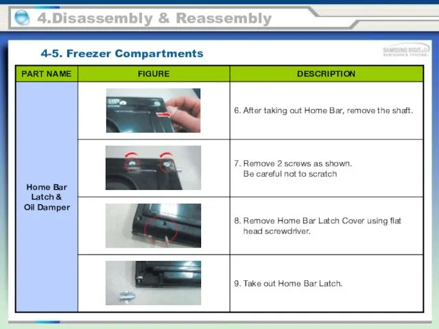
- 69. 4.Disassembly & Reassembly 4-5. Freezer Compartments
- 70. 4.Disassembly & Reassembly 4-5. Freezer Compartments
- 71. 4.Disassembly & Reassembly 4-5. Freezer Compartments
- 72. 4.Disassembly & Reassembly 4-5. Freezer Compartments
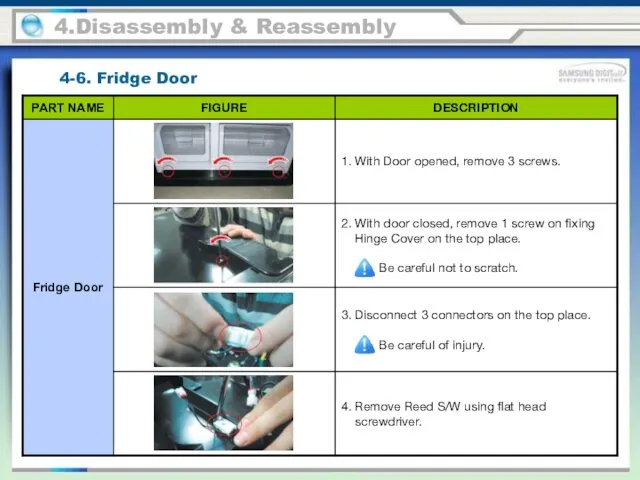
- 73. 4.Disassembly & Reassembly 4-6. Fridge Door
- 74. 4.Disassembly & Reassembly 4-6. Fridge Door
- 75. 4.Disassembly & Reassembly 4-6. Fridge Door
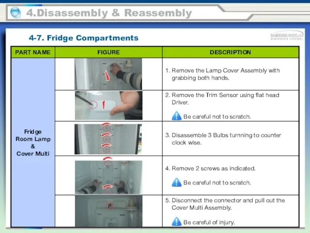
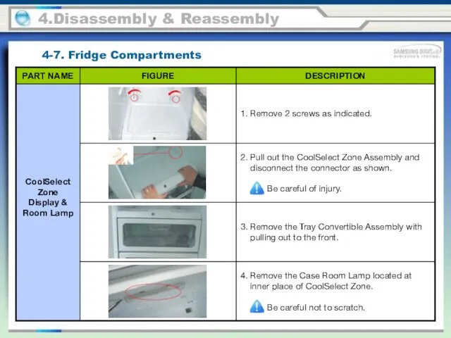
- 76. 4.Disassembly & Reassembly 4-7. Fridge Compartments
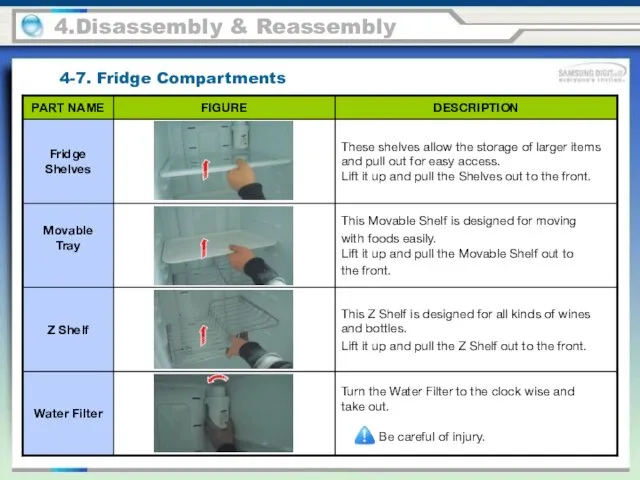
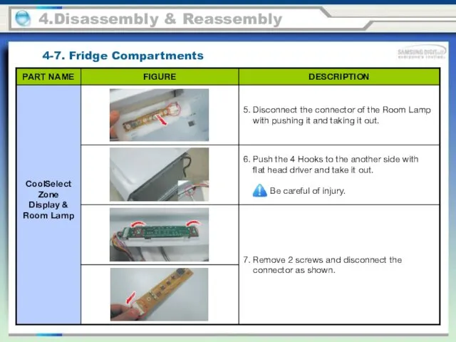
- 77. 4.Disassembly & Reassembly 4-7. Fridge Compartments
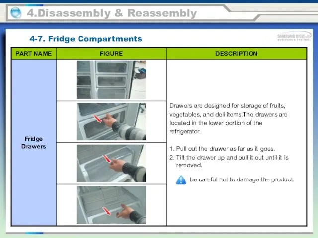
- 78. 4.Disassembly & Reassembly 4-7. Fridge Compartments
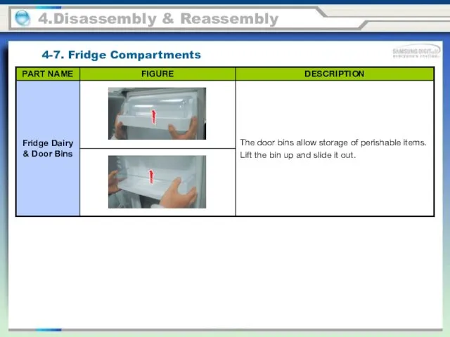
- 79. 4.Disassembly & Reassembly 4-7. Fridge Compartments
- 80. 4.Disassembly & Reassembly 4-7. Fridge Compartments
- 81. 4.Disassembly & Reassembly 4-7. Fridge Compartments
- 82. 4.Disassembly & Reassembly 4-7. Fridge Compartments
- 83. 4.Disassembly & Reassembly 4-7. Fridge Compartments
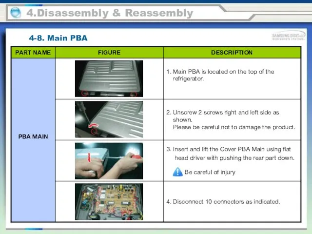
- 84. 4.Disassembly & Reassembly 4-8. Main PBA
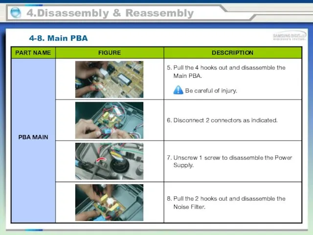
- 85. 4.Disassembly & Reassembly 4-8. Main PBA
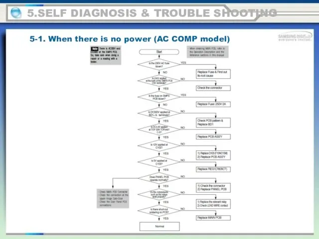
- 86. 5.SELF DIAGNOSIS & TROUBLE SHOOTING 5-1. When there is no power (AC COMP model)
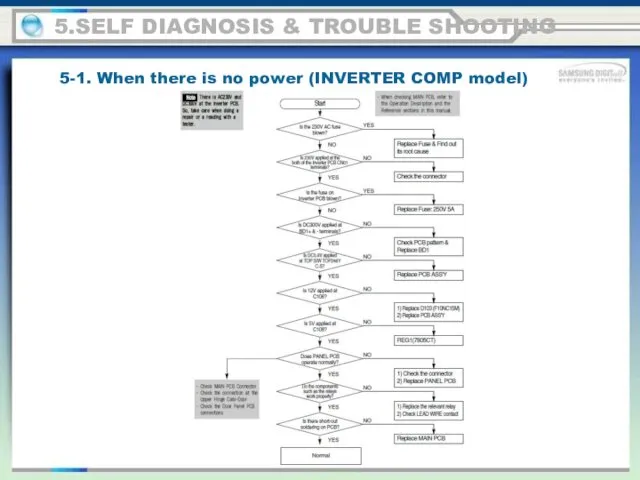
- 87. 5.SELF DIAGNOSIS & TROUBLE SHOOTING 5-1. When there is no power (INVERTER COMP model)
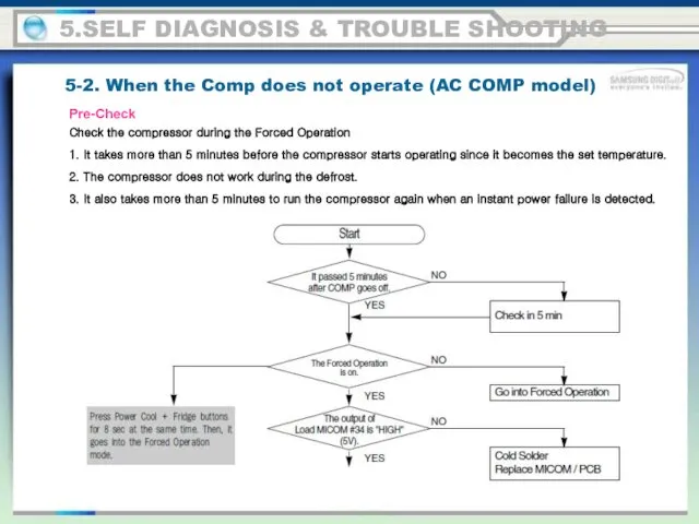
- 88. 5.SELF DIAGNOSIS & TROUBLE SHOOTING 5-2. When the Comp does not operate (AC COMP model) Check
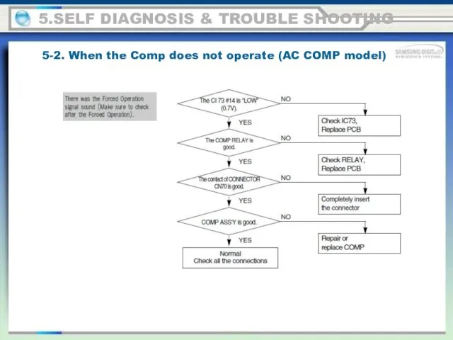
- 89. 5.SELF DIAGNOSIS & TROUBLE SHOOTING 5-2. When the Comp does not operate (AC COMP model)
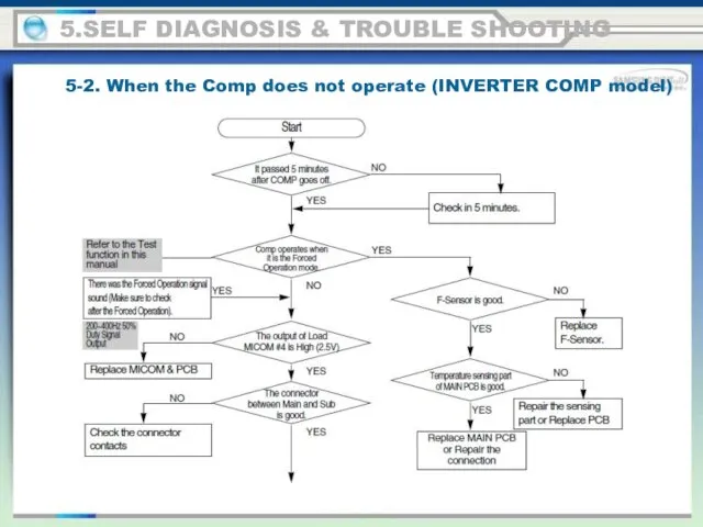
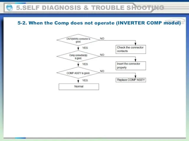
- 90. 5.SELF DIAGNOSIS & TROUBLE SHOOTING 5-2. When the Comp does not operate (INVERTER COMP model)
- 91. 5.SELF DIAGNOSIS & TROUBLE SHOOTING 5-2. When the Comp does not operate (INVERTER COMP model)
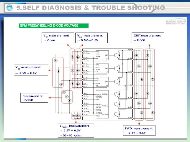
- 92. 5.SELF DIAGNOSIS & TROUBLE SHOOTING SPM FREEWHEELING DIODE VOLTAGE VBS measurement → Open VBS measurement →
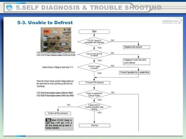
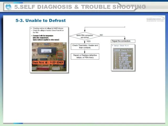
- 93. 5.SELF DIAGNOSIS & TROUBLE SHOOTING 5-3. Unable to Defrost
- 94. 5.SELF DIAGNOSIS & TROUBLE SHOOTING 5-3. Unable to Defrost
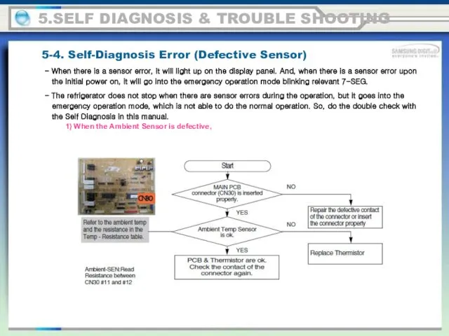
- 95. 5.SELF DIAGNOSIS & TROUBLE SHOOTING 5-4. Self-Diagnosis Error (Defective Sensor) 1) When the Ambient Sensor is
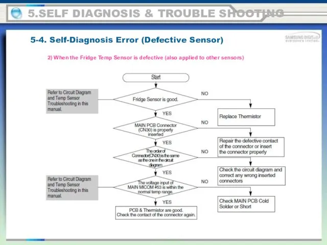
- 96. 5.SELF DIAGNOSIS & TROUBLE SHOOTING 5-4. Self-Diagnosis Error (Defective Sensor) 2) When the Fridge Temp Sensor
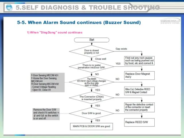
- 97. 5.SELF DIAGNOSIS & TROUBLE SHOOTING 5-5. When Alarm Sound continues (Buzzer Sound) 1) When "DingDong" sound
- 98. 5.SELF DIAGNOSIS & TROUBLE SHOOTING 5-5. When Alarm Sound continues (Buzzer Sound) 2) When "Beeping" sounds
- 99. 5.SELF DIAGNOSIS & TROUBLE SHOOTING 5-5. When Alarm Sound continues (Buzzer Sound) 3) No Buzzer Sound
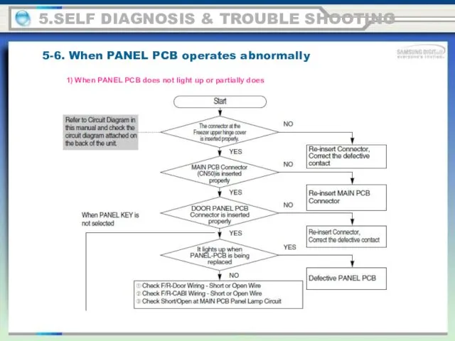
- 100. 5.SELF DIAGNOSIS & TROUBLE SHOOTING 5-6. When PANEL PCB operates abnormally 1) When PANEL PCB does
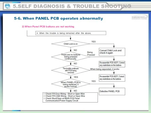
- 101. 5.SELF DIAGNOSIS & TROUBLE SHOOTING 5-6. When PANEL PCB operates abnormally 2) When Panel PCB buttons
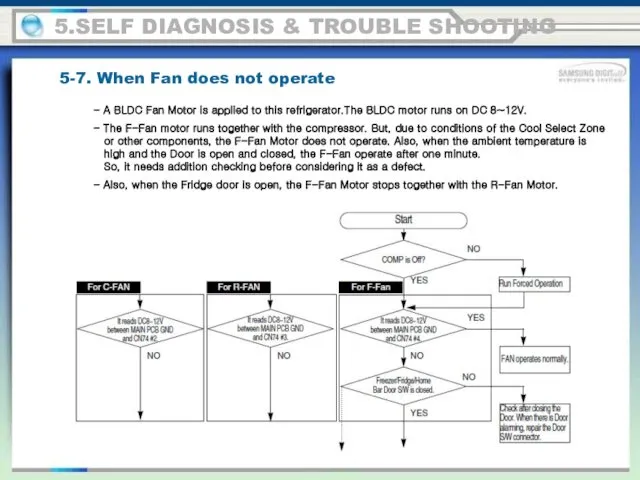
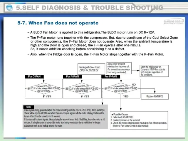
- 102. 5.SELF DIAGNOSIS & TROUBLE SHOOTING 5-7. When Fan does not operate - A BLDC Fan Motor
- 103. 5.SELF DIAGNOSIS & TROUBLE SHOOTING 5-7. When Fan does not operate - A BLDC Fan Motor
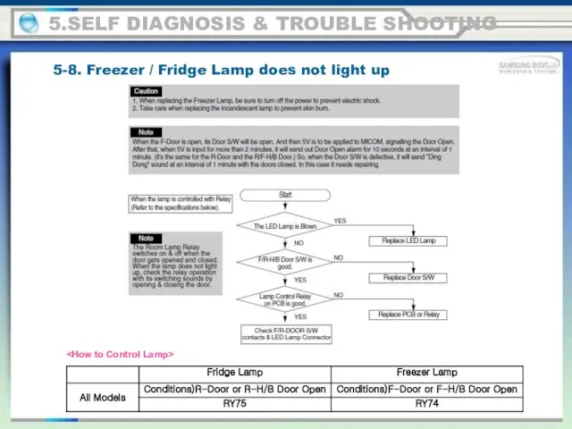
- 104. 5.SELF DIAGNOSIS & TROUBLE SHOOTING 5-8. Freezer / Fridge Lamp does not light up
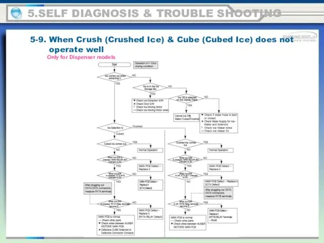
- 105. 5.SELF DIAGNOSIS & TROUBLE SHOOTING 5-9. When Crush (Crushed Ice) & Cube (Cubed Ice) does not
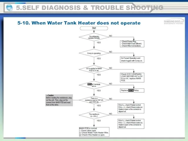
- 106. 5.SELF DIAGNOSIS & TROUBLE SHOOTING 5-10. When Water Tank Heater does not operate
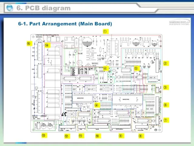
- 107. 6. PCB diagram 6-1. Part Arrangement (Main Board)
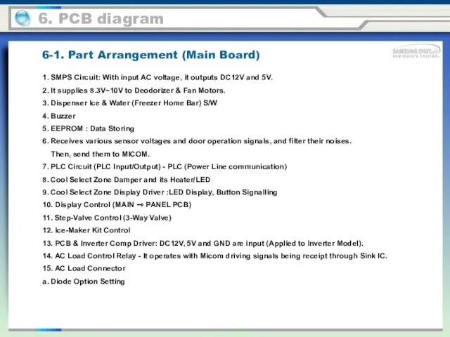
- 108. 6-1. Part Arrangement (Main Board) 1. SMPS Circuit: With input AC voltage, it outputs DC12V and
- 109. 6-2. Parts Layout (Inverter comp control Board) 1. PCB Power Source: SMPS Circuit It supplies DC12V,5V
- 110. 6-3. Connector Layout & Description (Main Board) 6. PCB diagram
- 111. 6-4. Connector Layout & Description (Inverter comp control Board) 6. PCB diagram Used for Inverter Model
- 112. 7-1. RSH5*** Series (CHINA Z-Option, Inverter COMP) 7. Wiring Diagram
- 113. 7-2. RSH5 Series (CHINA V/S-Option, Inverter COMP) 7. Wiring Diagram
- 114. 7-3. RSH5 Series (T-Option, Inverter COMP) 7. Wiring Diagram
- 115. 7-4. RSH5 Series (K-Option, Inverter COMP) 7. Wiring Diagram
- 116. 7-5. RSH5 Series (N-Option, Inverter COMP) 7. Wiring Diagram
- 117. 8-1. Main PCB Schematic Diagram - RSJ1 Series 8. Schematic Diagram
- 118. 8-2. BLOCK DIAGRAM (RSH5 Series ALL) 8. Schematic Diagram
- 119. 8-2. BLOCK DIAGRAM (RSH5 Z-OPTION) 8. Schematic Diagram
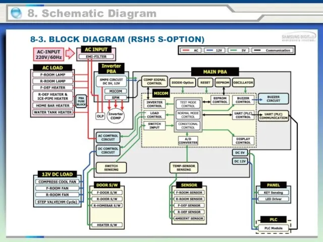
- 120. 8. Schematic Diagram 8-3. BLOCK DIAGRAM (RSH5 S-OPTION)
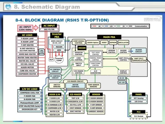
- 121. 8. Schematic Diagram 8-4. BLOCK DIAGRAM (RSH5 T/R-OPTION)
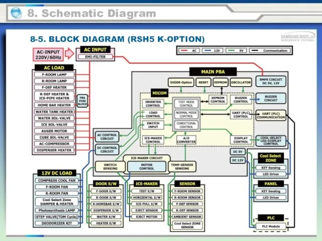
- 122. 8. Schematic Diagram 8-5. BLOCK DIAGRAM (RSH5 K-OPTION)
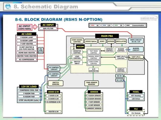
- 123. 8. Schematic Diagram 8-6. BLOCK DIAGRAM (RSH5 N-OPTION)
- 124. 9-1. RSJ1 Series (Nomenclature) 9.Reference Information BRAND : R-SAMSUNG REFRIGERATOR B-OEM REFRIGERATOR Function F : Full
- 125. 9-2. RSH1 Series (Nomenclature) 9.Reference Information BRAND : R-SAMSUNG REFRIGERATOR B-OEM REFRIGERATOR FUNCTION N :BASIC MODEL
- 126. 9-3. RSH5 Series (Nomenclature) 9.Reference Information BRAND : R-SAMSUNG REFRIGERATOR B-OEM REFRIGERATOR R S K SW
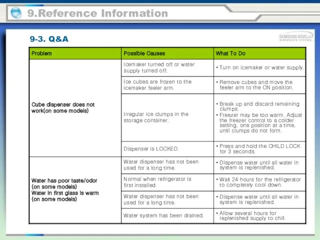
- 127. 9-3. Q&A 9.Reference Information
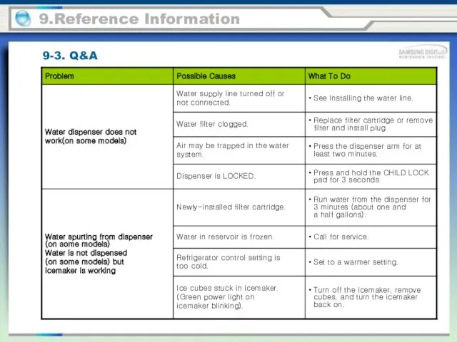
- 128. 9.Reference Information 9-3. Q&A
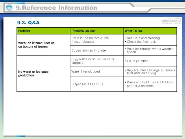
- 129. 9.Reference Information 9-3. Q&A
- 130. 9.Reference Information 9-3. Q&A
- 131. 9.Reference Information 9-3. Q&A
- 132. 9.Reference Information 9-3. Q&A
- 134. Скачать презентацию
Product Introduction
Instruction of Function
Alignment & Adjustment
Disassembly & Reassembly
SELF DIAGNOSIS & TROUBLE
Product Introduction
Instruction of Function
Alignment & Adjustment
Disassembly & Reassembly
SELF DIAGNOSIS & TROUBLE
1-1. Charcteristics
1.Product Introduction
● Comparison with basic
1-1. Charcteristics
1.Product Introduction
● Comparison with basic
1-1. Charcteristics
1.Product Introduction
● New Option
1-1. Charcteristics
1.Product Introduction
● New Option
1-1. Product Feature
1.Product Introduction
TWIN Cooling TDM
By monitoring the states of
1-1. Product Feature
1.Product Introduction
TWIN Cooling TDM By monitoring the states of
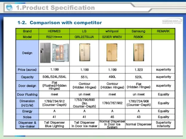
1-2. Comparison with competitor
1.Product Specification
1-2. Comparison with competitor
1.Product Specification
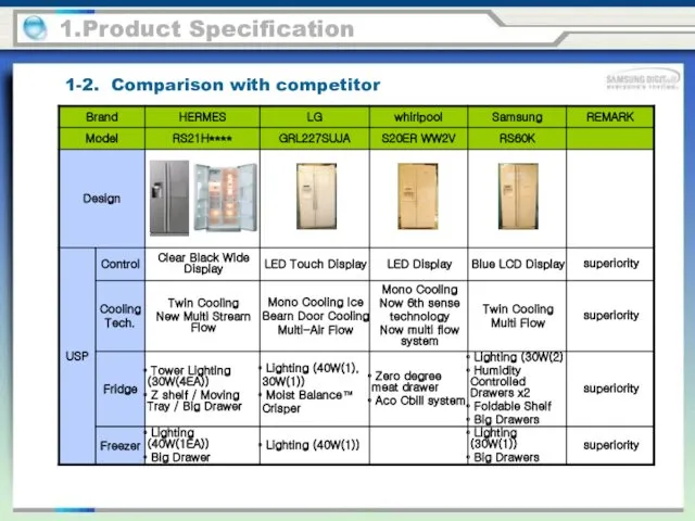
1-2. Comparison with competitor
1.Product Specification
1-2. Comparison with competitor
1.Product Specification
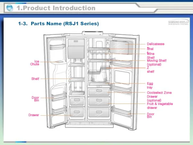
1-3. Parts Name (RSJ1 Series)
1.Product Introduction
Ice Chute
Door Bin
Coolselect Zone
Drawer (optional)
Drawer
Shelf
Egg
1-3. Parts Name (RSJ1 Series)
1.Product Introduction
Ice Chute
Door Bin
Coolselect Zone
Drawer (optional)
Drawer
Shelf
Egg
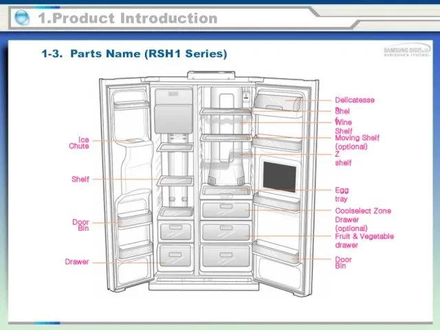
1-3. Parts Name (RSH1 Series)
1.Product Introduction
Ice Chute
Door Bin
Coolselect Zone
Drawer (optional)
Drawer
Shelf
Egg
1-3. Parts Name (RSH1 Series)
1.Product Introduction
Ice Chute
Door Bin
Coolselect Zone
Drawer (optional)
Drawer
Shelf
Egg
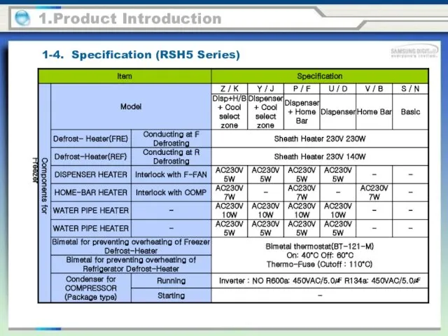
1-4. Specification (RSH5 Series)
1.Product Introduction
Components for Freezer
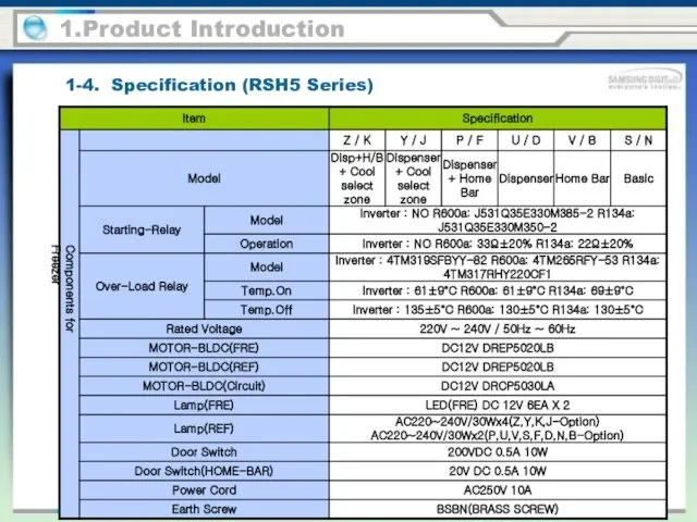
1-4. Specification (RSH5 Series)
1.Product Introduction
Components for Freezer
1-4. Specification (RSH5 Series)
1.Product Introduction
Components for Freezer
1-4. Specification (RSH5 Series)
1.Product Introduction
Components for Freezer
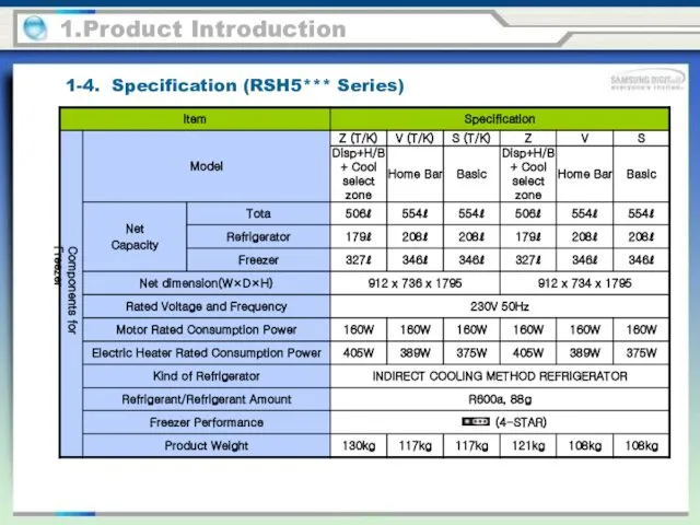
1-4. Specification (RSH5*** Series)
1.Product Introduction
Components for Freezer
1-4. Specification (RSH5*** Series)
1.Product Introduction
Components for Freezer
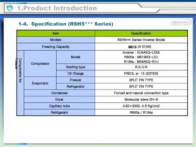
1-4. Specification (RSH5*** Series)
1.Product Introduction
Components for Freezer
1-4. Specification (RSH5*** Series)
1.Product Introduction
Components for Freezer
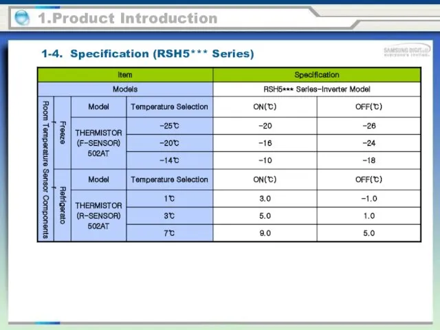
1.Product Introduction
Room Temperature Sensor Components
Freezer
Refrigerator
1-4. Specification (RSH5*** Series)
1.Product Introduction
Room Temperature Sensor Components
Freezer
Refrigerator
1-4. Specification (RSH5*** Series)
1.Product Introduction
Defrost Related Components
Freezer
Refrigerator
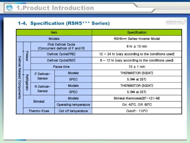
1-4. Specification (RSH5*** Series)
1.Product Introduction
Defrost Related Components
Freezer
Refrigerator
1-4. Specification (RSH5*** Series)
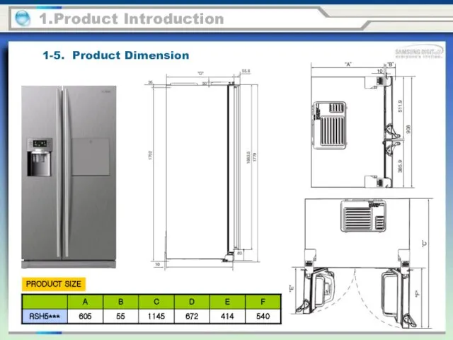
1-5. Product Dimension
1.Product Introduction
PRODUCT SIZE
1-5. Product Dimension
1.Product Introduction
PRODUCT SIZE
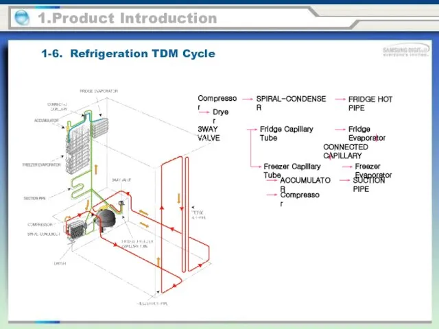
1-6. Refrigeration TDM Cycle
1.Product Introduction
Compressor
SPIRAL-CONDENSER
FRIDGE HOT PIPE
Dryer
3WAY VALVE
Fridge Capillary Tube
Fridge Evaporator
Freezer
1-6. Refrigeration TDM Cycle
1.Product Introduction
Compressor
SPIRAL-CONDENSER
FRIDGE HOT PIPE
Dryer
3WAY VALVE
Fridge Capillary Tube
Fridge Evaporator
Freezer
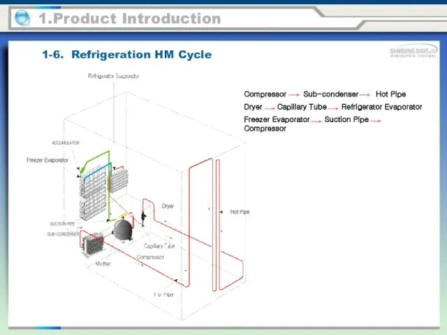
1-6. Refrigeration HM Cycle
1.Product Introduction
Compressor Sub-condenser Hot Pipe
Dryer Capillary Tube
1-6. Refrigeration HM Cycle
1.Product Introduction
Compressor Sub-condenser Hot Pipe
Dryer Capillary Tube
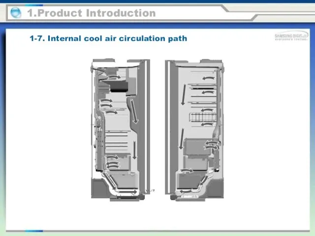
1-7. Internal cool air circulation path
1.Product Introduction
1-7. Internal cool air circulation path
1.Product Introduction
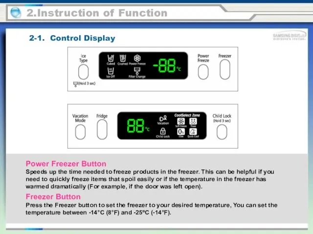
2-1. Control Display
2.Instruction of Function
Power Freezer Button
Speeds up the time needed
2-1. Control Display
2.Instruction of Function
Power Freezer Button
Speeds up the time needed
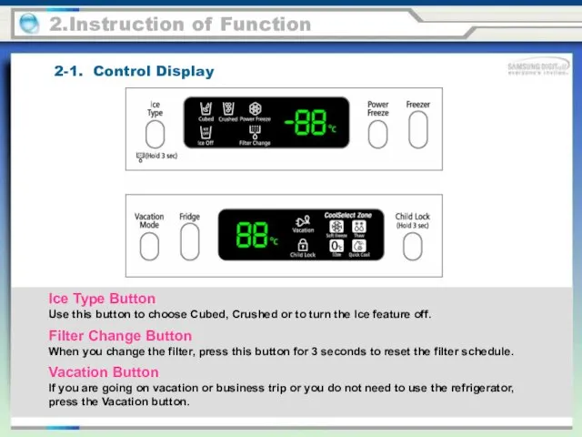
Filter Change Button
When you change the filter, press this button for
Filter Change Button
When you change the filter, press this button for
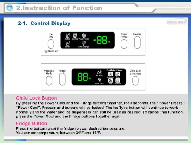
Child Lock Button
By pressing the Power Cool and the Fridge buttons
Child Lock Button
By pressing the Power Cool and the Fridge buttons
2-2. FRESH SELECT ZONE™ DRAWER GUIDE
Power Freeze
This icon will light up
2-2. FRESH SELECT ZONE™ DRAWER GUIDE
Power Freeze
This icon will light up
2-2. FRESH SELECT ZONE™ DRAWER GUIDE
2.Instruction of Function
Filter Indicator
When the
2-2. FRESH SELECT ZONE™ DRAWER GUIDE
2.Instruction of Function
Filter Indicator
When the
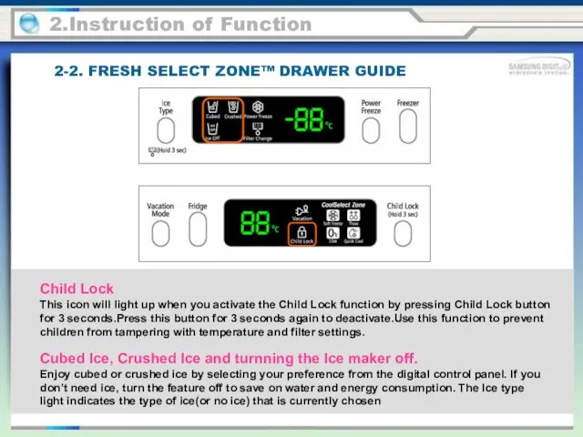
Child Lock
This icon will light up when you activate the Child
Child Lock This icon will light up when you activate the Child
2-3. Ice Maker Function
2.Instruction of Function
The Ice Maker produces ice automatically
2-3. Ice Maker Function
2.Instruction of Function
The Ice Maker produces ice automatically
2.Instruction of Function
1) Initial Operation
1-1) At the initial power on,
2.Instruction of Function
1) Initial Operation
1-1) At the initial power on,
2.Instruction of Function
4) Ice Ejection
● The Ice Ejection is an
2.Instruction of Function
4) Ice Ejection
● The Ice Ejection is an
2.Instruction of Function
5-3) When it completes water supplying, it will
2.Instruction of Function
5-3) When it completes water supplying, it will
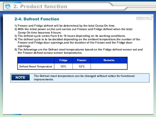
1) Freezer and Fridge defrost will be determined by the total
1) Freezer and Fridge defrost will be determined by the total
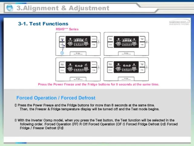
Forced Operation / Forced Defrost
3-1. Test Functions
3.Alignment & Adjustment
Press the
Forced Operation / Forced Defrost
3-1. Test Functions
3.Alignment & Adjustment
Press the
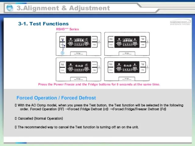
Forced Operation / Forced Defrost
3-1. Test Functions
3.Alignment & Adjustment
With the
Forced Operation / Forced Defrost
3-1. Test Functions
3.Alignment & Adjustment
With the
3-2. Self-Diagnostics
3.Alignment & Adjustment
Self-Diagnosis Function upon Initial Power-On
1) When the unit
3-2. Self-Diagnostics
3.Alignment & Adjustment
Self-Diagnosis Function upon Initial Power-On
1) When the unit
3-2. Self-Diagnostics
3.Alignment & Adjustment
Self-Diagnosis Function during Normal Operation
1) When the the
3-2. Self-Diagnostics
3.Alignment & Adjustment
Self-Diagnosis Function during Normal Operation
1) When the the
3.Alignment & Adjustment
3-2. Self-Diagnostics
Self-Diagnostics Check List
When any of the above segments
3.Alignment & Adjustment
3-2. Self-Diagnostics
Self-Diagnostics Check List
When any of the above segments
3.Alignment & Adjustment
3-2. Self-Diagnostics
Self-Diagnostics Check List
3.Alignment & Adjustment
3-2. Self-Diagnostics
Self-Diagnostics Check List
3.Alignment & Adjustment
3-2. Self-Diagnostics
Self-Diagnostics Check List
3.Alignment & Adjustment
3-2. Self-Diagnostics
Self-Diagnostics Check List
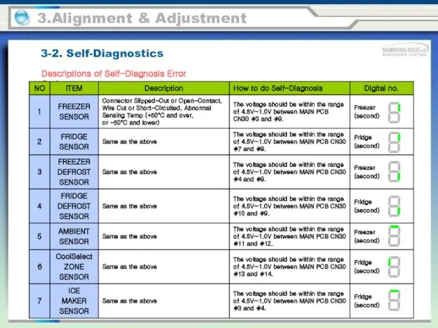
3.Alignment & Adjustment
3-2. Self-Diagnostics
Descriptions of Self-Diagnosis Error Code
3.Alignment & Adjustment
3-2. Self-Diagnostics
Descriptions of Self-Diagnosis Error Code
3.Alignment & Adjustment
3-2. Self-Diagnostics
Descriptions of Self-Diagnosis Error Code
3.Alignment & Adjustment
3-2. Self-Diagnostics
Descriptions of Self-Diagnosis Error Code
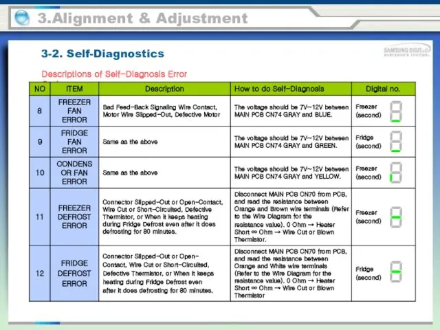
3.Alignment & Adjustment
3-2. Self-Diagnostics
Descriptions of Self-Diagnosis Error Code
3.Alignment & Adjustment
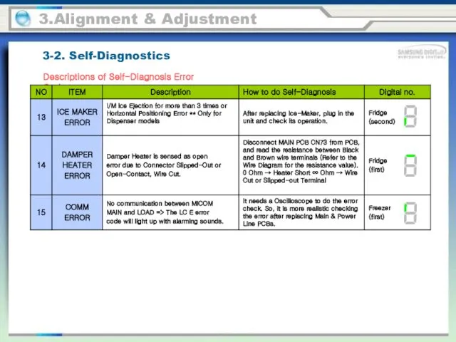
3-2. Self-Diagnostics
Descriptions of Self-Diagnosis Error Code
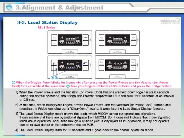
3-3. Load Status Display
3.Alignment & Adjustment
1) When the Power Freeze and
3-3. Load Status Display
3.Alignment & Adjustment
1) When the Power Freeze and
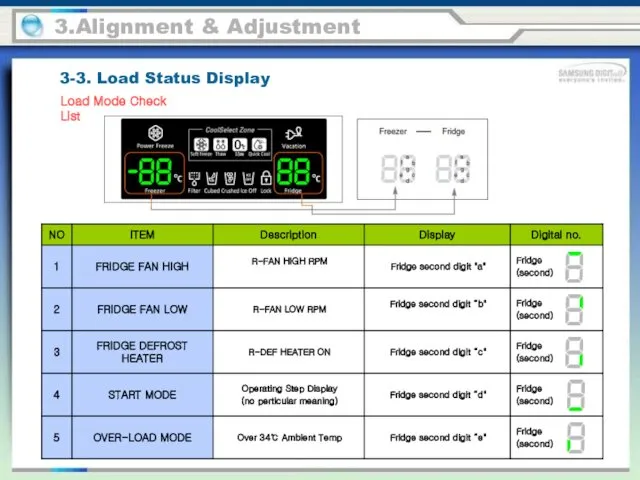
3.Alignment & Adjustment
Load Mode Check List
3-3. Load Status Display
3.Alignment & Adjustment
Load Mode Check List
3-3. Load Status Display
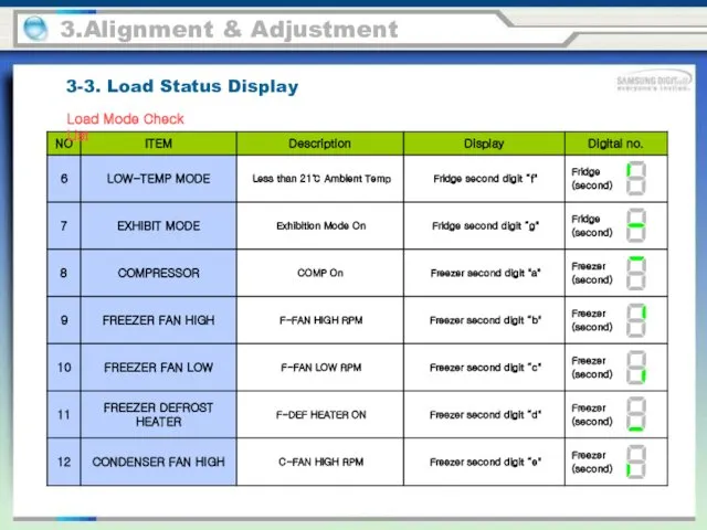
3.Alignment & Adjustment
Load Mode Check List
3-3. Load Status Display
3.Alignment & Adjustment
Load Mode Check List
3-3. Load Status Display
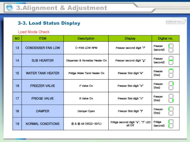
3.Alignment & Adjustment
Load Mode Check List
3-3. Load Status Display
3.Alignment & Adjustment
Load Mode Check List
3-3. Load Status Display
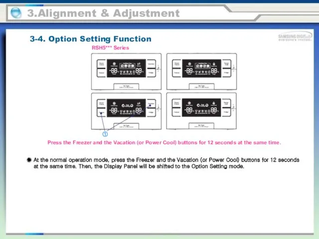
3.Alignment & Adjustment
3-4. Option Setting Function
Press the Freezer and the Vacation
3.Alignment & Adjustment
3-4. Option Setting Function
Press the Freezer and the Vacation
※ Button Operation at Option Setting Mode
3.Alignment & Adjustment
3-4. Option Setting
※ Button Operation at Option Setting Mode
3.Alignment & Adjustment
3-4. Option Setting
3.Alignment & Adjustment
3-4. Option Setting Function
When the display is converted
3.Alignment & Adjustment
3-4. Option Setting Function
When the display is converted
3.Alignment & Adjustment
3-4. Option Setting Function
There are more functions which can
3.Alignment & Adjustment
3-4. Option Setting Function
There are more functions which can
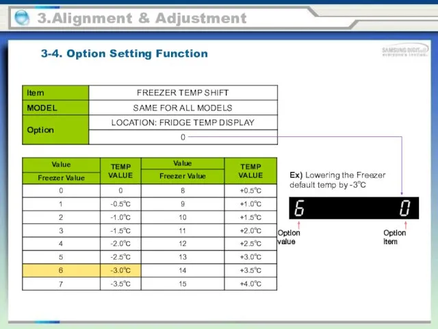
Ex) Lowering the Freezer default temp by -3℃
3.Alignment & Adjustment
Option value
Option
Ex) Lowering the Freezer default temp by -3℃
3.Alignment & Adjustment
Option value
Option
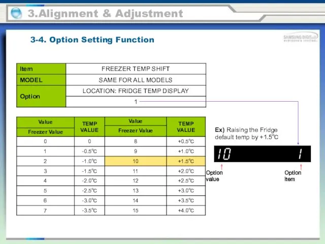
Ex) Raising the Fridge default temp by +1.5℃
3.Alignment & Adjustment
Option value
Option
Ex) Raising the Fridge default temp by +1.5℃
3.Alignment & Adjustment
Option value
Option
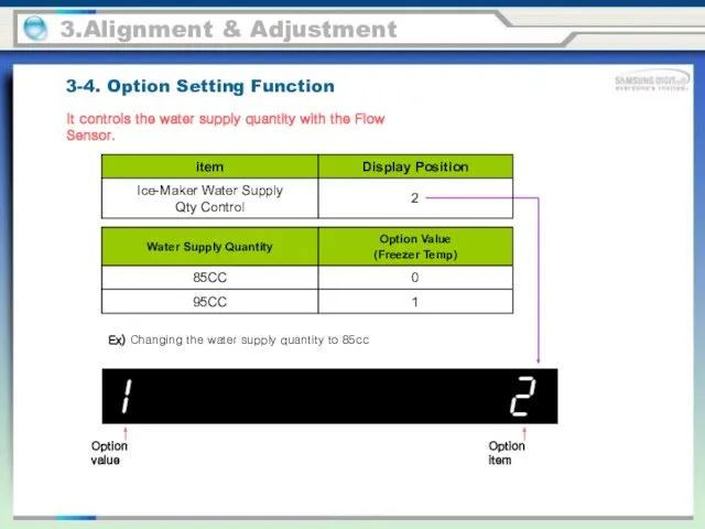
Ex) Changing the water supply quantity to 85cc
3.Alignment & Adjustment
It controls
Ex) Changing the water supply quantity to 85cc
3.Alignment & Adjustment
It controls
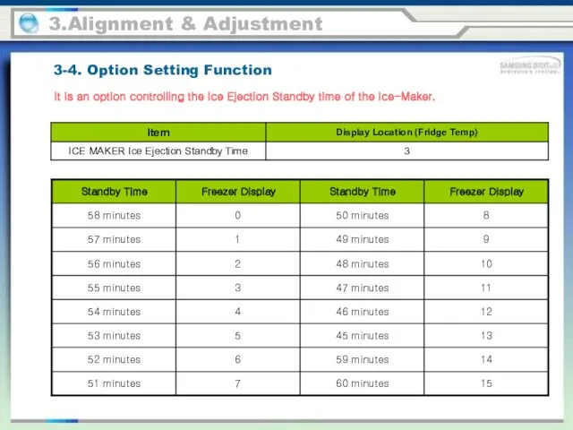
3.Alignment & Adjustment
It is an option controlling the Ice Ejection Standby
3.Alignment & Adjustment
It is an option controlling the Ice Ejection Standby
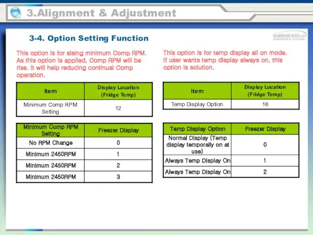
3.Alignment & Adjustment
This option is for sising minimum Comp RPM. As
3.Alignment & Adjustment
This option is for sising minimum Comp RPM. As
3.Alignment & Adjustment
It is an option shifting the ice ejecting base
3.Alignment & Adjustment
It is an option shifting the ice ejecting base
3.Alignment & Adjustment
It is an option shifting the Cool Select Zone
3.Alignment & Adjustment
It is an option shifting the Cool Select Zone
4-1. Necessary tools for disassembly and reassembly
4.Disassembly & Reassembly
• Unplug the
4-1. Necessary tools for disassembly and reassembly
4.Disassembly & Reassembly
• Unplug the
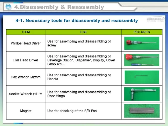
4-1. Necessary tools for disassembly and reassembly
4.Disassembly & Reassembly
4-1. Necessary tools for disassembly and reassembly
4.Disassembly & Reassembly
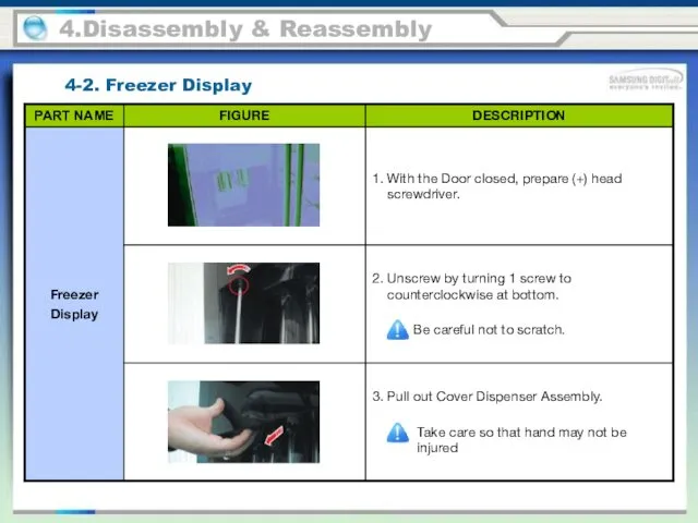
4-2. Freezer Display
4.Disassembly & Reassembly
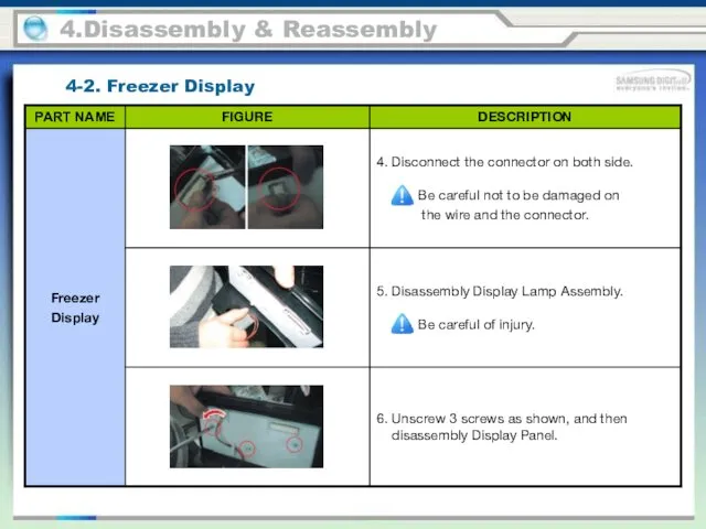
4-2. Freezer Display
4.Disassembly & Reassembly
4-2. Freezer Display
4.Disassembly & Reassembly
4-2. Freezer Display
4.Disassembly & Reassembly
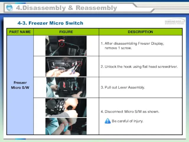
4-3. Freezer Micro Switch
4.Disassembly & Reassembly
4-3. Freezer Micro Switch
4.Disassembly & Reassembly
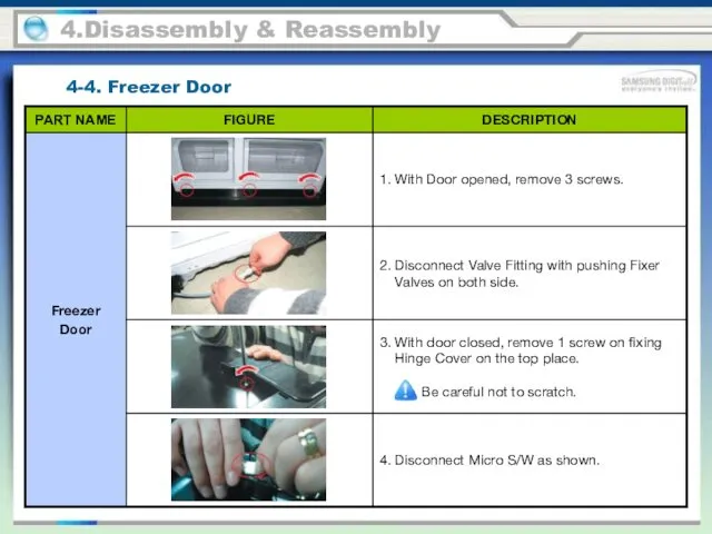
4-4. Freezer Door
4.Disassembly & Reassembly
4-4. Freezer Door
4.Disassembly & Reassembly
4-4. Freezer Door
4.Disassembly & Reassembly
4-4. Freezer Door
4.Disassembly & Reassembly
4.Disassembly & Reassembly
4-5. Freezer Compartments
4.Disassembly & Reassembly
4-5. Freezer Compartments
4.Disassembly & Reassembly
4-5. Freezer Compartments
4.Disassembly & Reassembly
4-5. Freezer Compartments
4.Disassembly & Reassembly
4-5. Freezer Compartments
4.Disassembly & Reassembly
4-5. Freezer Compartments
4.Disassembly & Reassembly
4-5. Freezer Compartments
4.Disassembly & Reassembly
4-5. Freezer Compartments
4.Disassembly & Reassembly
4-5. Freezer Compartments
4.Disassembly & Reassembly
4-5. Freezer Compartments
4.Disassembly & Reassembly
4-5. Freezer Compartments
4.Disassembly & Reassembly
4-5. Freezer Compartments
4.Disassembly & Reassembly
4-5. Freezer Compartments
4.Disassembly & Reassembly
4-5. Freezer Compartments
4.Disassembly & Reassembly
4-5. Freezer Compartments
4.Disassembly & Reassembly
4-5. Freezer Compartments
4.Disassembly & Reassembly
4-5. Freezer Compartments
4.Disassembly & Reassembly
4-5. Freezer Compartments
4.Disassembly & Reassembly
4-5. Freezer Compartments
4.Disassembly & Reassembly
4-5. Freezer Compartments
4.Disassembly & Reassembly
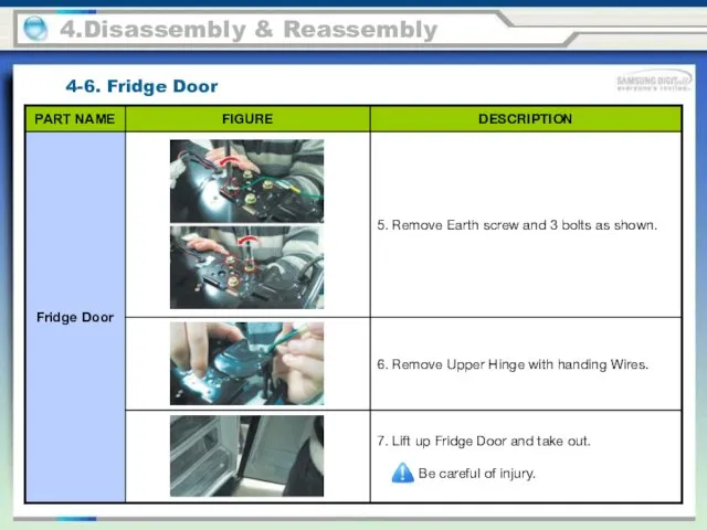
4-6. Fridge Door
4.Disassembly & Reassembly
4-6. Fridge Door
4.Disassembly & Reassembly
4-6. Fridge Door
4.Disassembly & Reassembly
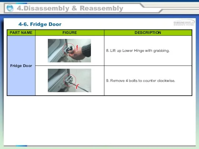
4-6. Fridge Door
4.Disassembly & Reassembly
4-6. Fridge Door
4.Disassembly & Reassembly
4-6. Fridge Door
4.Disassembly & Reassembly
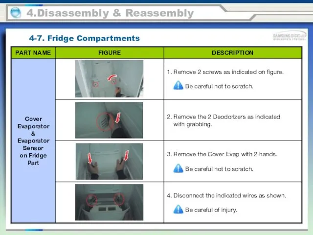
4-7. Fridge Compartments
4.Disassembly & Reassembly
4-7. Fridge Compartments
4.Disassembly & Reassembly
4-7. Fridge Compartments
4.Disassembly & Reassembly
4-7. Fridge Compartments
4.Disassembly & Reassembly
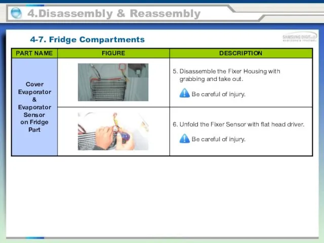
4-7. Fridge Compartments
4.Disassembly & Reassembly
4-7. Fridge Compartments
4.Disassembly & Reassembly
4-7. Fridge Compartments
4.Disassembly & Reassembly
4-7. Fridge Compartments
4.Disassembly & Reassembly
4-7. Fridge Compartments
4.Disassembly & Reassembly
4-7. Fridge Compartments
4.Disassembly & Reassembly
4-7. Fridge Compartments
4.Disassembly & Reassembly
4-7. Fridge Compartments
4.Disassembly & Reassembly
4-7. Fridge Compartments
4.Disassembly & Reassembly
4-7. Fridge Compartments
4.Disassembly & Reassembly
4-7. Fridge Compartments
4.Disassembly & Reassembly
4-7. Fridge Compartments
4.Disassembly & Reassembly
4-8. Main PBA
4.Disassembly & Reassembly
4-8. Main PBA
4.Disassembly & Reassembly
4-8. Main PBA
4.Disassembly & Reassembly
4-8. Main PBA
5.SELF DIAGNOSIS & TROUBLE SHOOTING
5-1. When there is no power (AC
5.SELF DIAGNOSIS & TROUBLE SHOOTING
5-1. When there is no power (AC
5.SELF DIAGNOSIS & TROUBLE SHOOTING
5-1. When there is no power (INVERTER
5.SELF DIAGNOSIS & TROUBLE SHOOTING
5-1. When there is no power (INVERTER
5.SELF DIAGNOSIS & TROUBLE SHOOTING
5-2. When the Comp does not operate
5.SELF DIAGNOSIS & TROUBLE SHOOTING
5-2. When the Comp does not operate
5.SELF DIAGNOSIS & TROUBLE SHOOTING
5-2. When the Comp does not operate
5.SELF DIAGNOSIS & TROUBLE SHOOTING
5-2. When the Comp does not operate
5.SELF DIAGNOSIS & TROUBLE SHOOTING
5-2. When the Comp does not operate
5.SELF DIAGNOSIS & TROUBLE SHOOTING
5-2. When the Comp does not operate
5.SELF DIAGNOSIS & TROUBLE SHOOTING
5-2. When the Comp does not operate
5.SELF DIAGNOSIS & TROUBLE SHOOTING
5-2. When the Comp does not operate
5.SELF DIAGNOSIS & TROUBLE SHOOTING
SPM FREEWHEELING DIODE VOLTAGE
VBS measurement → Open
VBS
5.SELF DIAGNOSIS & TROUBLE SHOOTING
SPM FREEWHEELING DIODE VOLTAGE
VBS measurement → Open
VBS
5.SELF DIAGNOSIS & TROUBLE SHOOTING
5-3. Unable to Defrost
5.SELF DIAGNOSIS & TROUBLE SHOOTING
5-3. Unable to Defrost
5.SELF DIAGNOSIS & TROUBLE SHOOTING
5-3. Unable to Defrost
5.SELF DIAGNOSIS & TROUBLE SHOOTING
5-3. Unable to Defrost
5.SELF DIAGNOSIS & TROUBLE SHOOTING
5-4. Self-Diagnosis Error (Defective Sensor)
1) When the
5.SELF DIAGNOSIS & TROUBLE SHOOTING
5-4. Self-Diagnosis Error (Defective Sensor)
1) When the
5.SELF DIAGNOSIS & TROUBLE SHOOTING
5-4. Self-Diagnosis Error (Defective Sensor)
2) When the
5.SELF DIAGNOSIS & TROUBLE SHOOTING
5-4. Self-Diagnosis Error (Defective Sensor)
2) When the
5.SELF DIAGNOSIS & TROUBLE SHOOTING
5-5. When Alarm Sound continues (Buzzer Sound)
1)
5.SELF DIAGNOSIS & TROUBLE SHOOTING
5-5. When Alarm Sound continues (Buzzer Sound)
1)
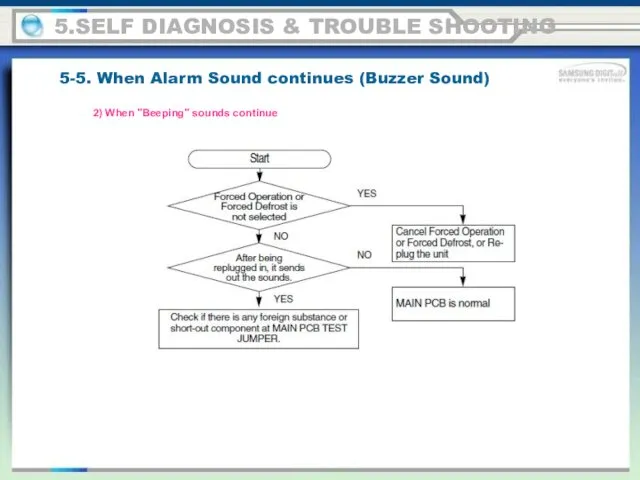
5.SELF DIAGNOSIS & TROUBLE SHOOTING
5-5. When Alarm Sound continues (Buzzer Sound)
2)
5.SELF DIAGNOSIS & TROUBLE SHOOTING
5-5. When Alarm Sound continues (Buzzer Sound)
2)
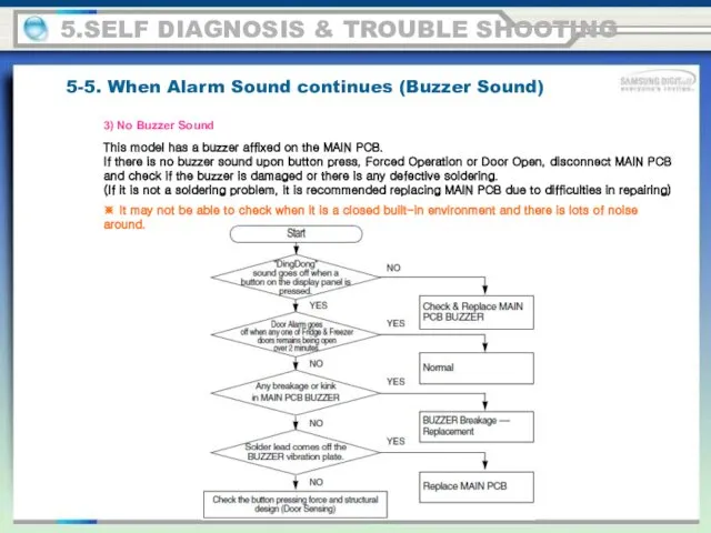
5.SELF DIAGNOSIS & TROUBLE SHOOTING
5-5. When Alarm Sound continues (Buzzer Sound)
3)
5.SELF DIAGNOSIS & TROUBLE SHOOTING
5-5. When Alarm Sound continues (Buzzer Sound)
3)
5.SELF DIAGNOSIS & TROUBLE SHOOTING
5-6. When PANEL PCB operates abnormally
1) When
5.SELF DIAGNOSIS & TROUBLE SHOOTING
5-6. When PANEL PCB operates abnormally
1) When
5.SELF DIAGNOSIS & TROUBLE SHOOTING
5-6. When PANEL PCB operates abnormally
2) When
5.SELF DIAGNOSIS & TROUBLE SHOOTING
5-6. When PANEL PCB operates abnormally
2) When
5.SELF DIAGNOSIS & TROUBLE SHOOTING
5-7. When Fan does not operate
- A
5.SELF DIAGNOSIS & TROUBLE SHOOTING
5-7. When Fan does not operate
- A
5.SELF DIAGNOSIS & TROUBLE SHOOTING
5-7. When Fan does not operate
- A
5.SELF DIAGNOSIS & TROUBLE SHOOTING
5-7. When Fan does not operate
- A
5.SELF DIAGNOSIS & TROUBLE SHOOTING
5-8. Freezer / Fridge Lamp does not
5.SELF DIAGNOSIS & TROUBLE SHOOTING
5-8. Freezer / Fridge Lamp does not
5.SELF DIAGNOSIS & TROUBLE SHOOTING
5-9. When Crush (Crushed Ice) & Cube
5.SELF DIAGNOSIS & TROUBLE SHOOTING
5-9. When Crush (Crushed Ice) & Cube
5.SELF DIAGNOSIS & TROUBLE SHOOTING
5-10. When Water Tank Heater does not
5.SELF DIAGNOSIS & TROUBLE SHOOTING
5-10. When Water Tank Heater does not
6. PCB diagram
6-1. Part Arrangement (Main Board)
6. PCB diagram
6-1. Part Arrangement (Main Board)
6-1. Part Arrangement (Main Board)
1. SMPS Circuit: With input AC voltage,
6-1. Part Arrangement (Main Board)
1. SMPS Circuit: With input AC voltage,
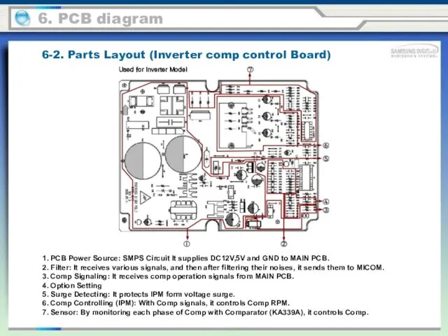
6-2. Parts Layout (Inverter comp control Board)
1. PCB Power Source: SMPS
6-2. Parts Layout (Inverter comp control Board)
1. PCB Power Source: SMPS
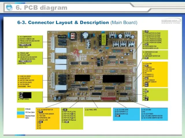
6-3. Connector Layout & Description (Main Board)
6. PCB diagram
6-3. Connector Layout & Description (Main Board)
6. PCB diagram
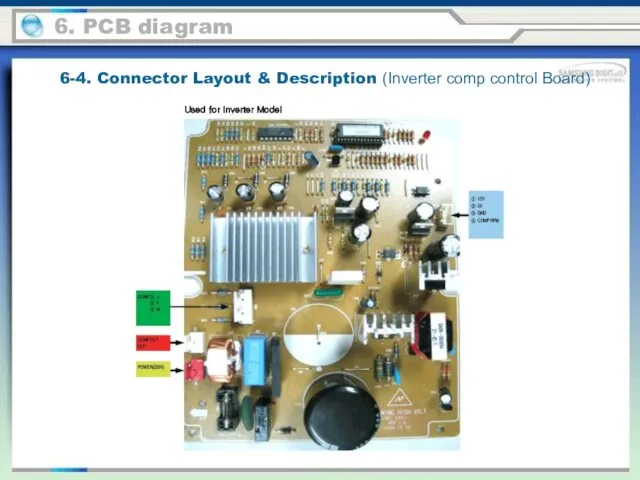
6-4. Connector Layout & Description (Inverter comp control Board)
6. PCB diagram
Used
6-4. Connector Layout & Description (Inverter comp control Board)
6. PCB diagram
Used
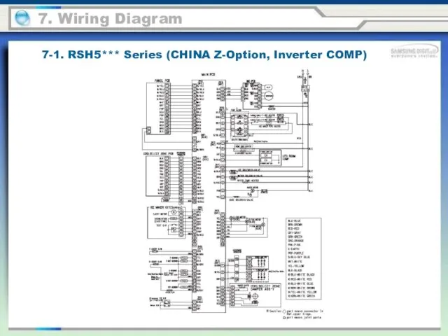
7-1. RSH5*** Series (CHINA Z-Option, Inverter COMP)
7. Wiring Diagram
7-1. RSH5*** Series (CHINA Z-Option, Inverter COMP)
7. Wiring Diagram
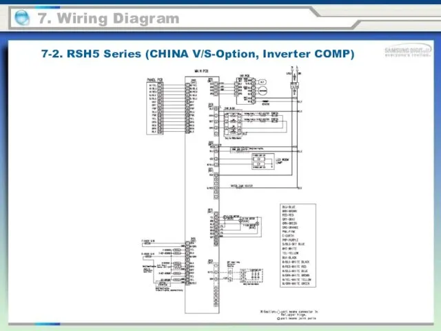
7-2. RSH5 Series (CHINA V/S-Option, Inverter COMP)
7. Wiring Diagram
7-2. RSH5 Series (CHINA V/S-Option, Inverter COMP)
7. Wiring Diagram
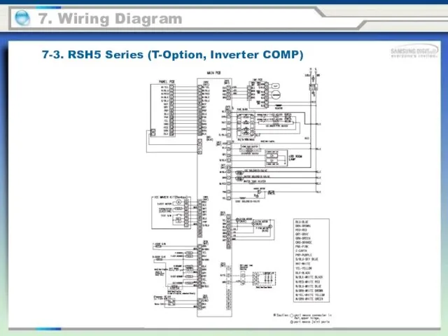
7-3. RSH5 Series (T-Option, Inverter COMP)
7. Wiring Diagram
7-3. RSH5 Series (T-Option, Inverter COMP)
7. Wiring Diagram
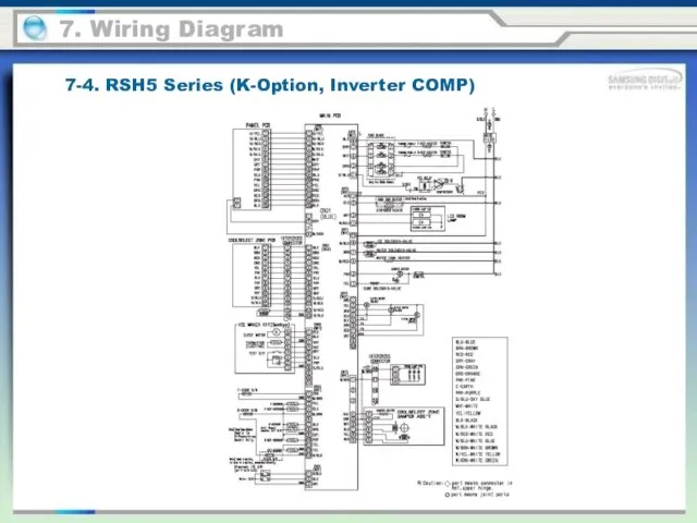
7-4. RSH5 Series (K-Option, Inverter COMP)
7. Wiring Diagram
7-4. RSH5 Series (K-Option, Inverter COMP)
7. Wiring Diagram
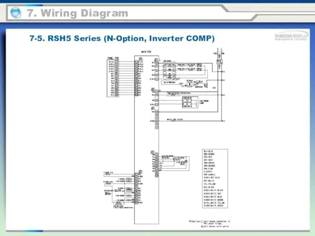
7-5. RSH5 Series (N-Option, Inverter COMP)
7. Wiring Diagram
7-5. RSH5 Series (N-Option, Inverter COMP)
7. Wiring Diagram
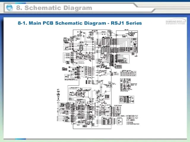
8-1. Main PCB Schematic Diagram - RSJ1 Series
8. Schematic Diagram
8-1. Main PCB Schematic Diagram - RSJ1 Series
8. Schematic Diagram
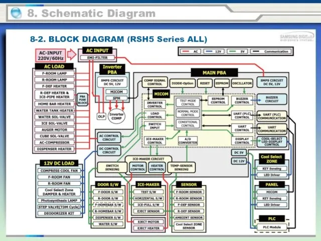
8-2. BLOCK DIAGRAM (RSH5 Series ALL)
8. Schematic Diagram
8-2. BLOCK DIAGRAM (RSH5 Series ALL)
8. Schematic Diagram
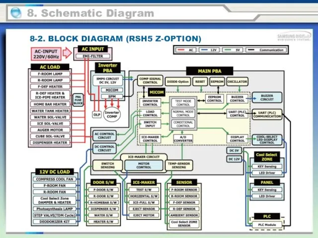
8-2. BLOCK DIAGRAM (RSH5 Z-OPTION)
8. Schematic Diagram
8-2. BLOCK DIAGRAM (RSH5 Z-OPTION)
8. Schematic Diagram
8. Schematic Diagram
8-3. BLOCK DIAGRAM (RSH5 S-OPTION)
8. Schematic Diagram
8-3. BLOCK DIAGRAM (RSH5 S-OPTION)
8. Schematic Diagram
8-4. BLOCK DIAGRAM (RSH5 T/R-OPTION)
8. Schematic Diagram
8-4. BLOCK DIAGRAM (RSH5 T/R-OPTION)
8. Schematic Diagram
8-5. BLOCK DIAGRAM (RSH5 K-OPTION)
8. Schematic Diagram
8-5. BLOCK DIAGRAM (RSH5 K-OPTION)
8. Schematic Diagram
8-6. BLOCK DIAGRAM (RSH5 N-OPTION)
8. Schematic Diagram
8-6. BLOCK DIAGRAM (RSH5 N-OPTION)
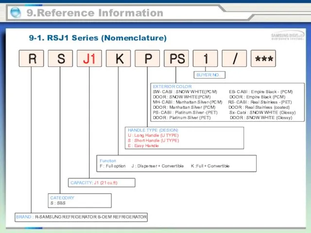
9-1. RSJ1 Series (Nomenclature)
9.Reference Information
BRAND : R-SAMSUNG REFRIGERATOR B-OEM REFRIGERATOR
Function
F
9-1. RSJ1 Series (Nomenclature)
9.Reference Information
BRAND : R-SAMSUNG REFRIGERATOR B-OEM REFRIGERATOR
Function F
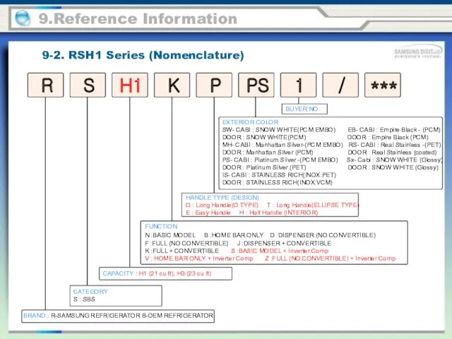
9-2. RSH1 Series (Nomenclature)
9.Reference Information
BRAND : R-SAMSUNG REFRIGERATOR B-OEM REFRIGERATOR
FUNCTION
N :BASIC
9-2. RSH1 Series (Nomenclature)
9.Reference Information
BRAND : R-SAMSUNG REFRIGERATOR B-OEM REFRIGERATOR
FUNCTION N :BASIC
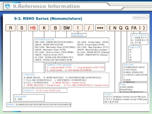
9-3. RSH5 Series (Nomenclature)
9.Reference Information
BRAND : R-SAMSUNG REFRIGERATOR B-OEM REFRIGERATOR
R
S
K
SW
B
H5
1
/
***
CATEGORY
S :
9-3. RSH5 Series (Nomenclature)
9.Reference Information
BRAND : R-SAMSUNG REFRIGERATOR B-OEM REFRIGERATOR
R
S
K
SW
B
H5
1
/
***
CATEGORY S :
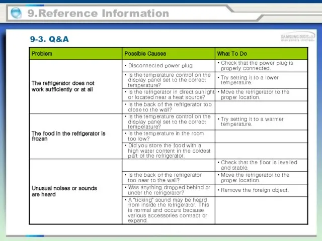
9-3. Q&A
9.Reference Information
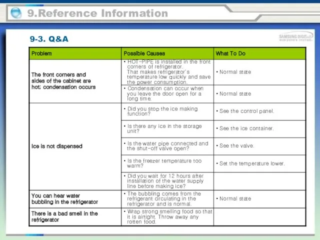
9-3. Q&A
9.Reference Information
9.Reference Information
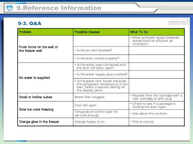
9-3. Q&A
9.Reference Information
9-3. Q&A
9.Reference Information
9-3. Q&A
9.Reference Information
9-3. Q&A
9.Reference Information
9-3. Q&A
9.Reference Information
9-3. Q&A
9.Reference Information
9-3. Q&A
9.Reference Information
9-3. Q&A
9.Reference Information
9-3. Q&A
9.Reference Information
9-3. Q&A
 Лествица Великого поста
 Презентация Притча о доброте
 Исследовательская работа Я на радугу-дугу полюбуюсь, побегу!
 Быть здоровым - это модно!
 Противовоспалительные средства (ПВС)
 Гармония. Адаптивная физическая культура
 20231101_prezentatsiya_k_uroku_matematiki_6_kl._po_teme_dlina_okruzhnosti
 Презентация к уроку Классификация химических реакций
 Методы и средства профилактики заболеваний пародонта
 Виды инфляции. Дисциплина: Финансы и кредит
 ЭКОЛОГИЧЕСКИЕ ПРОБЛЕМЫ
 Презентация Глобализация и современное образование
 Тотожні перетворення раціональних виразів
 Проект технологического процесса по изготовлению женского жакета в ателье высшего разряда
 Сергиево-Посадская нефтебаза
 Менін дінім ислам діні
 Эксплуатация и мониторинг технического состояния зданий и сооружений
 Линейные электрические цепи постоянного тока. Лекция 1
 Цели и задачи интегрированного занятия
 Технология изготовления и сборка тумбы стеллажа
 6.2.Общее устройство ТЗА
 Эталоны единиц величин бесконтактных средств измерений температуры
 Поступление на магистратуру
 What is your favorite fruit?
 Стили и направления в моде
 ПФ РФ. Представление корректирующих ИС
 Анна Шапарева. Самопрезентация
 Тригонометрические уравнения