- Innovative metallurgical technology

Содержание
- 2. DESIGNATION Compact high-tech metallugical complex (CHMC-50) is designed for small sections of rolled steel to GOST
- 3. Table 1 Parameters of the metallurgical complex CHMC-50.
- 4. Table 2 Technical characteristics of equipment metallurgical complex CHMC-50.
- 5. Table 3 Total consumption of basic energy resources.
- 6. Fig. 1 Layout of complex equipment Designation of positions on Table 2
- 7. FEATURES HIGH METALLURGICAL TECHNOLOGY The new approach is considered a fundamental difference of metallurgical technology, is
- 8. A process flow diagram
- 9. Figure 2. Special centrifugal casting machine. 1. Casting ladle, 2. Stand, 3. Mold, 4. Ring blank,
- 10. Figure 5. Dressing machine 1. Frame of roller guide, 2. Drive rollers of the roller guide,
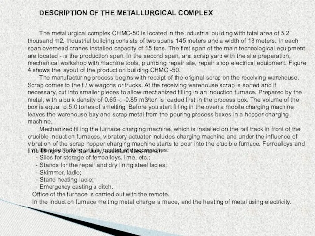
- 11. DESCRIPTION OF THE METALLURGICAL COMPLEX The metallurgical complex CHMC-50 is located in the industrial building with
- 12. Upon reaching the desired chemical composition and temperature of the melt, the metal poured into the
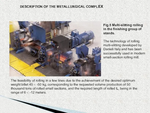
- 13. DESCRIPTION OF THE METALLURGICAL COMPLEX Fig.5 Multi-slitting rolling in the finishing group of stands. The technology
- 14. DESCRIPTION OF THE METALLURGICAL COMPLEX Fig.6 Scheme of calibration rolls in the finishing group of stands
- 15. DESCRIPTION OF THE METALLURGICAL COMPLEX Bars, up to 12 meters, arrive at a chain cooling bed.
- 16. Fig.4 Layout production building CHMC-50.
- 18. Скачать презентацию
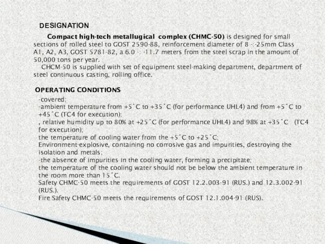
DESIGNATION
Compact high-tech metallugical complex (CHMC-50) is designed for small
DESIGNATION
Compact high-tech metallugical complex (CHMC-50) is designed for small
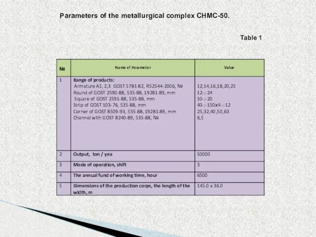
Table 1
Parameters of the metallurgical complex CHMC-50.
Table 1
Parameters of the metallurgical complex CHMC-50.
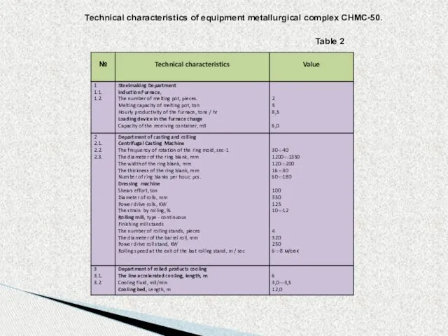
Table 2
Technical characteristics of equipment metallurgical complex CHMC-50.
Table 2
Technical characteristics of equipment metallurgical complex CHMC-50.
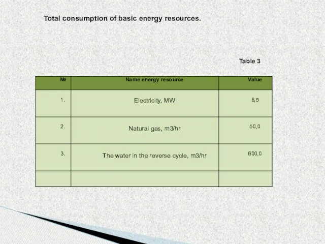
Table 3
Total consumption of basic energy resources.
Table 3
Total consumption of basic energy resources.
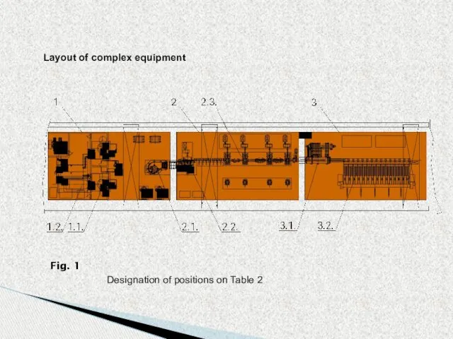
Fig. 1
Layout of complex equipment
Designation of positions on Table 2
Fig. 1
Layout of complex equipment
Designation of positions on Table 2
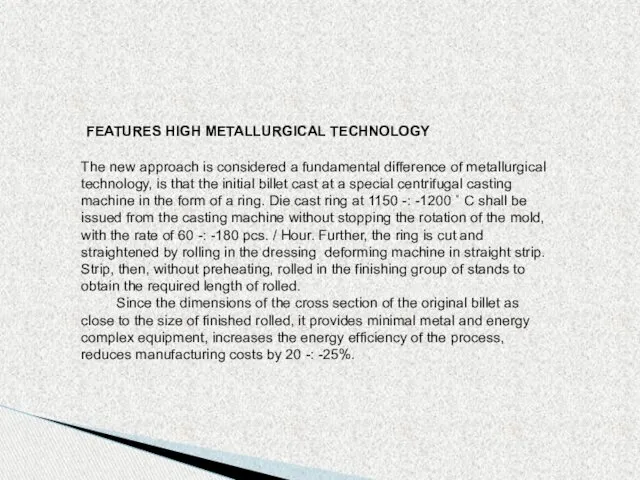
FEATURES HIGH METALLURGICAL TECHNOLOGY
The new approach is considered a fundamental difference
FEATURES HIGH METALLURGICAL TECHNOLOGY
The new approach is considered a fundamental difference
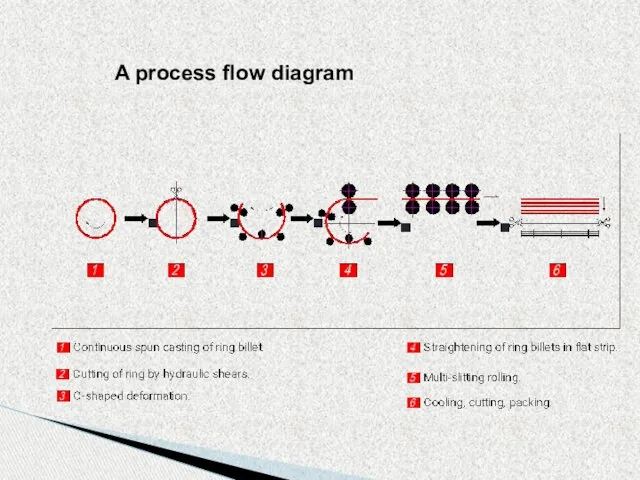
A process flow diagram
A process flow diagram
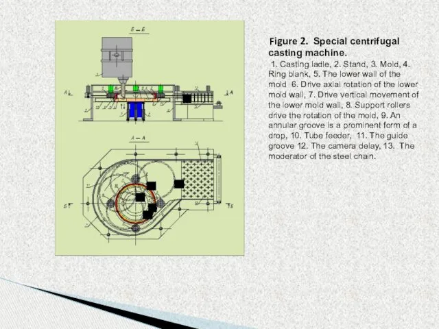
Figure 2. Special centrifugal casting machine.
1. Casting ladle,
Figure 2. Special centrifugal casting machine.
1. Casting ladle,
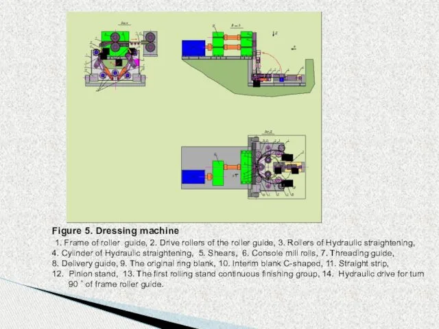
Figure 5. Dressing machine
1. Frame of roller guide, 2. Drive
Figure 5. Dressing machine
1. Frame of roller guide, 2. Drive
DESCRIPTION OF THE METALLURGICAL COMPLEX
The metallurgical complex CHMC-50 is located in
DESCRIPTION OF THE METALLURGICAL COMPLEX
The metallurgical complex CHMC-50 is located in
Upon reaching the desired chemical composition and temperature of the melt,
Upon reaching the desired chemical composition and temperature of the melt,
DESCRIPTION OF THE METALLURGICAL COMPLEX
Fig.5 Multi-slitting rolling in the finishing group
DESCRIPTION OF THE METALLURGICAL COMPLEX
Fig.5 Multi-slitting rolling in the finishing group
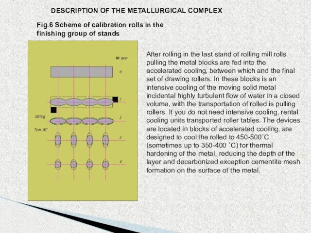
DESCRIPTION OF THE METALLURGICAL COMPLEX
Fig.6 Scheme of calibration rolls in the
DESCRIPTION OF THE METALLURGICAL COMPLEX
Fig.6 Scheme of calibration rolls in the
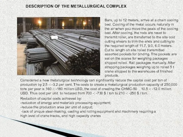
DESCRIPTION OF THE METALLURGICAL COMPLEX
Bars, up to 12 meters, arrive at
DESCRIPTION OF THE METALLURGICAL COMPLEX
Bars, up to 12 meters, arrive at
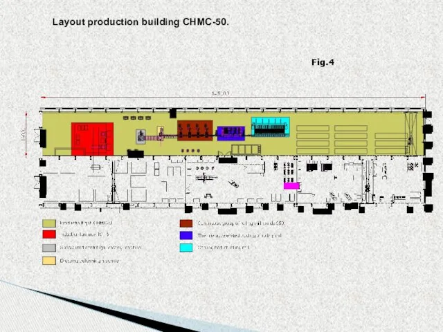
Fig.4
Layout production building CHMC-50.
Fig.4
Layout production building CHMC-50.
 Оксиды серы (IV) и (VI). Производство серной кислоты
 Цветная металлургия
 Составление рассказа по картине Кошка с котятами
 Родительское собрание
 Как мы готовимся к смотру- параду юнармейских отрядов
 Изменения, выборы, голосование
 Работа с родителями
 Национальная экономика
 Развитие Дальнего Востока в XXI века
 Letter Writing - Useful Words & Expressions
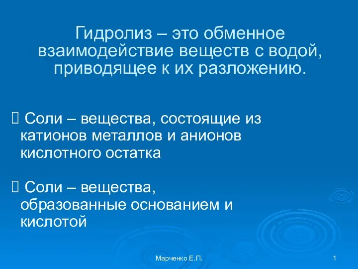 Презентация по теме Гидролиз
 Портативні комп’ютери
 Генераторы гармонических колебаний
 Тренажер по математике
 Олимпийские игры в древней Греции: система обслуживания спортсменов и гостей
 Введение в процедурное программирование. Управляющие инструкции
 Ғимараттардың конструктивтік түрлері (типі) және сұлбалары
 Правонарушения и юридическая ответственность
 Електронні датчики системи керування ДВЗ
 Тест по темеТипы кристаллических решёток, 8 класс
 Символьные и строковые величины. Программа сравнения двух символов
 Технология производства полуфабрикатов из картофеля в ооо белгородский консервный комбинат
 Метапредметные результаты освоения ООП
 Линия по производству труб в ППУ оболочке
 Индивидуальные различия, связанные с особенностями психических процессов, способностей и интеллекта
 Опасные и неблагоприятные явления природы
 Правовое регулирование пенсионного обеспечения в случае потери кормильца в Российской Федерации
 Пародонт ауруымен ауыратын балаларды емдеуде физиотерапиялық әдістерді қолдану