- Light RTM (LRTM) Moulding “Mould build technology

Содержание
- 2. Master Model Orientation Flange Surface Draft angle Release agent
- 3. Master Model Orientation
- 4. Lounger pattern Flange Dual level flanging Simple flange
- 5. Flange/seal rules
- 6. Primary and secondary seals may follow different paths
- 7. Corner radii restriction must be observed Seals placed on pattern to simulate paths
- 8. Other Flange examples 130 mm +/- 5mm Flange direction change
- 9. Master Model -Pinch off detail
- 10. Inserts in the first mould flange Flange vacuum Injection port Alternatives Autosprue 10mm pipe
- 11. Location of inserts on master pattern
- 12. Injection port on Face tool
- 13. Inserts illustrated Flange vacuum insert Autosprue insert
- 14. General mould cross section
- 15. Typical VM mould production set up
- 16. Location - Dowelling X and y location
- 17. Peripheral Fill Resin mould flow designed to find initial easy path around cavity. Ideal - path
- 18. Flow path built into Mould flange
- 20. 4m² small craft VM mould - filling
- 21. Reality
- 22. More Flow shots
- 23. Face tool Lay up Release agent Tooling gel coat VE Tissue + VE First layer 450
- 24. Calibration of first mould
- 25. Seals and flow channel profiles
- 26. Seals and profiles
- 27. Resin Runner Profile In face mould or contra mould
- 28. Resin runner position
- 29. Two vacuum levels Vacuum 1 to clamp mould flange. At least 85% providing 1 tonne/linear m.
- 30. Air driven vacuum control
- 31. Accuracy is the Key – Vacuum lock during LRTM Mould build
- 32. Total Cost of moulds Mould material costs £340 / m² Labour costs average 30 hrs /m²
- 33. High Volume VM up to 800/ day!
- 34. VM will mould Small to Large Parts
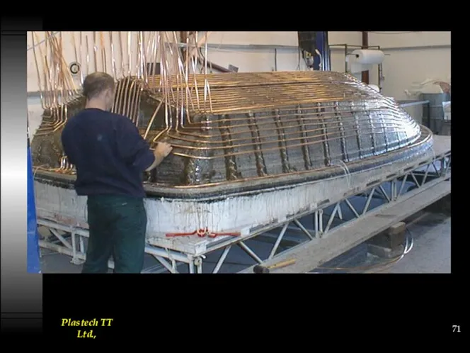
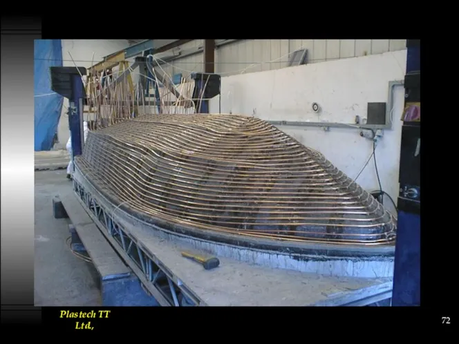
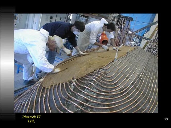
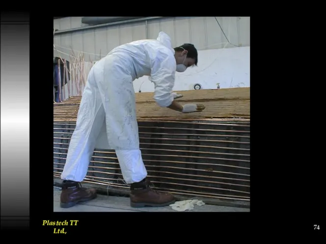
- 35. LRTM can go big and complicated
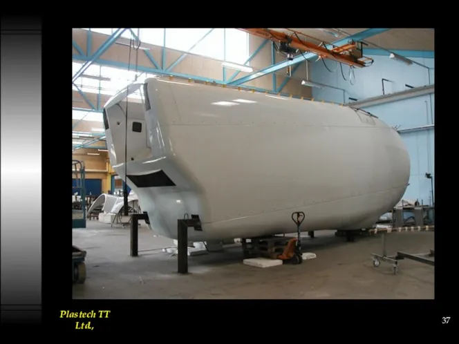
- 36. Wind Turbine housing – approx. 100 m2 surface area
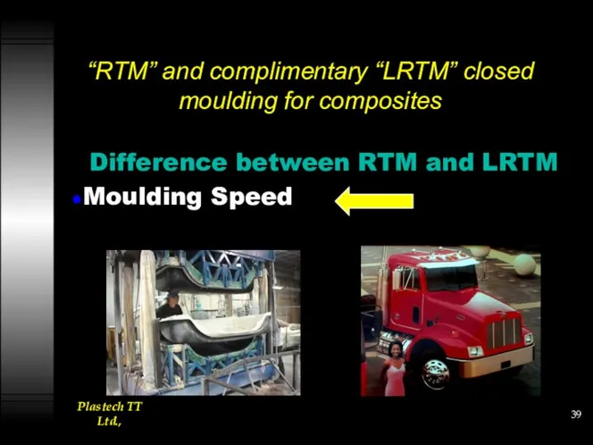
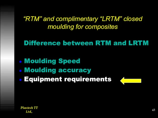
- 38. Difference between RTM and LRTM Moulding Speed Moulding accuracy Equipment requirements
- 39. “RTM” and complimentary “LRTM” closed moulding for composites Difference between RTM and LRTM Moulding Speed
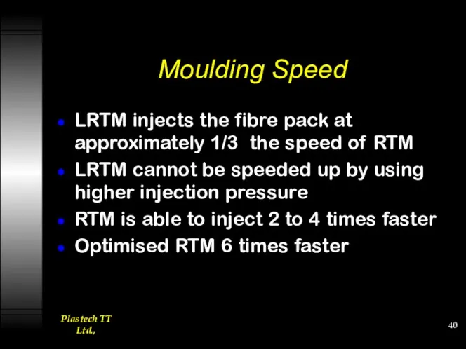
- 40. Moulding Speed LRTM injects the fibre pack at approximately 1/3 the speed of RTM LRTM cannot
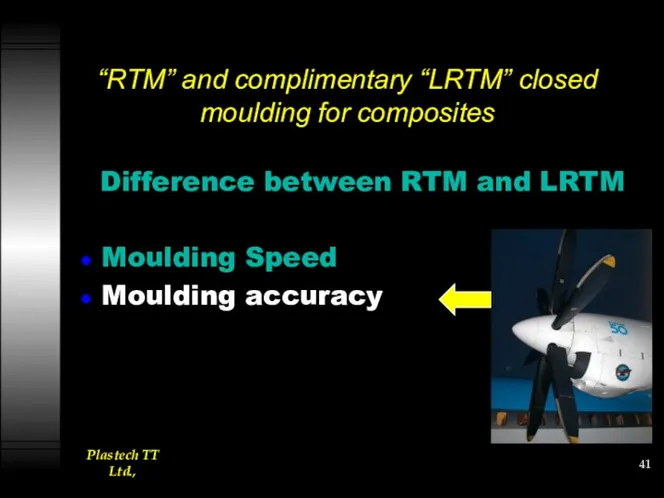
- 41. “RTM” and complimentary “LRTM” closed moulding for composites Difference between RTM and LRTM Moulding Speed Moulding
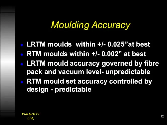
- 42. Moulding Accuracy LRTM moulds within +/- 0.025”at best RTM moulds within +/- 0.002” at best LRTM
- 43. “RTM” and complimentary “LRTM” closed moulding for composites Difference between RTM and LRTM Moulding Speed Moulding
- 44. Equipment requirements RTM needs a low pressure meter mix machine and tool manipulator. LRTM needs a
- 45. Low pressure LRTM Machine Mould Pressure Guard Regulates speed of pump to achieve safe low pressure
- 46. More Application examples
- 47. Sunlounger
- 48. Pacific Composites - Australia
- 49. Invalid Bath
- 50. 10mm thick 80kg VE resin
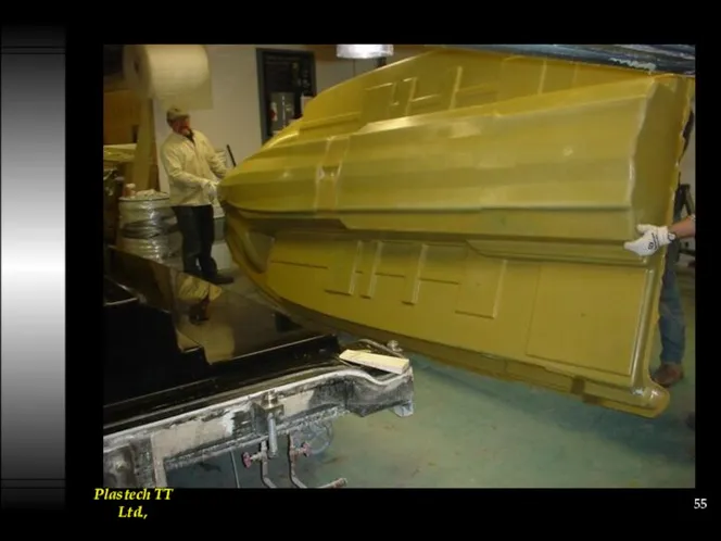
- 53. VM can go big and complicated
- 56. Other VM applications
- 57. Conclusions LRTM is a viable lower cost system complimentary to RTM. Tooling manufacture must be accurate
- 58. Heating /Temperature control
- 59. Electrical Heater-Cloth Application.
- 76. Скачать презентацию
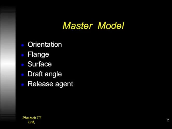
Master Model
Orientation
Flange
Surface
Draft angle
Release agent
Master Model
Orientation
Flange
Surface
Draft angle
Release agent
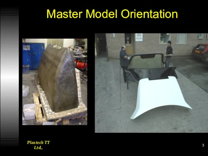
Master Model Orientation
Master Model Orientation
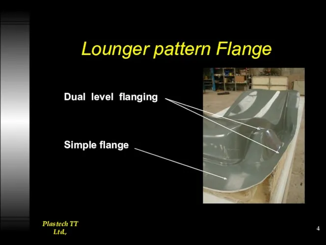
Lounger pattern Flange
Dual level flanging
Simple flange
Lounger pattern Flange
Dual level flanging
Simple flange
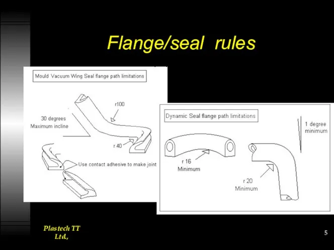
Flange/seal rules
Flange/seal rules
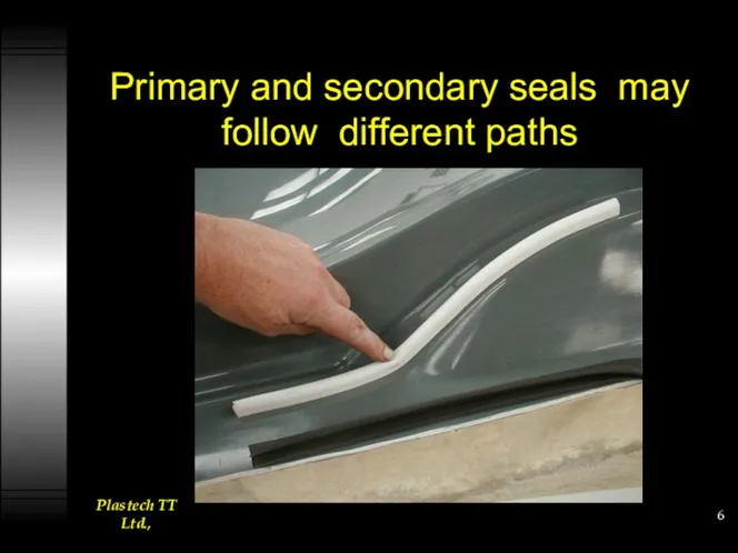
Primary and secondary seals may follow different paths
Primary and secondary seals may follow different paths
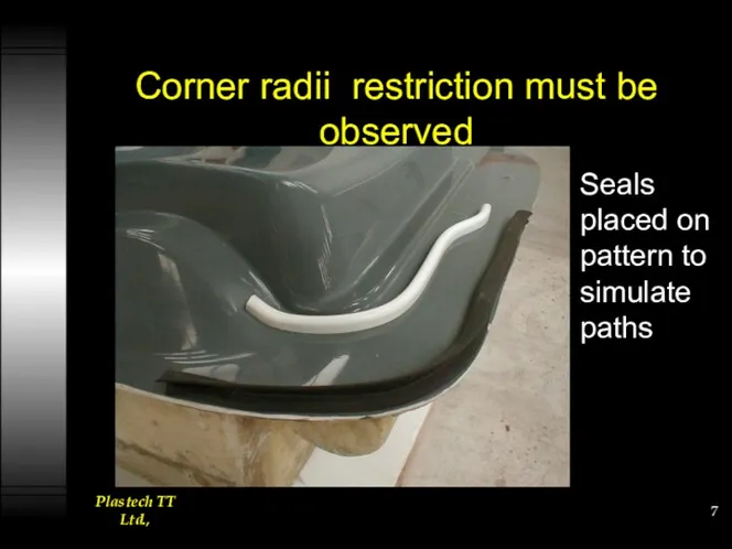
Corner radii restriction must be observed
Seals placed on pattern to simulate
Corner radii restriction must be observed
Seals placed on pattern to simulate
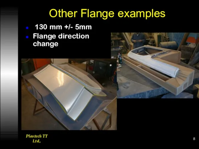
Other Flange examples
130 mm +/- 5mm
Flange direction change
Other Flange examples
130 mm +/- 5mm
Flange direction change
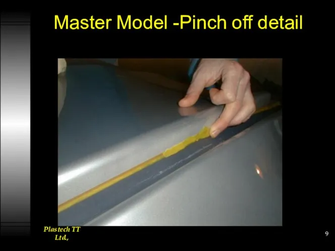
Master Model -Pinch off detail
Master Model -Pinch off detail
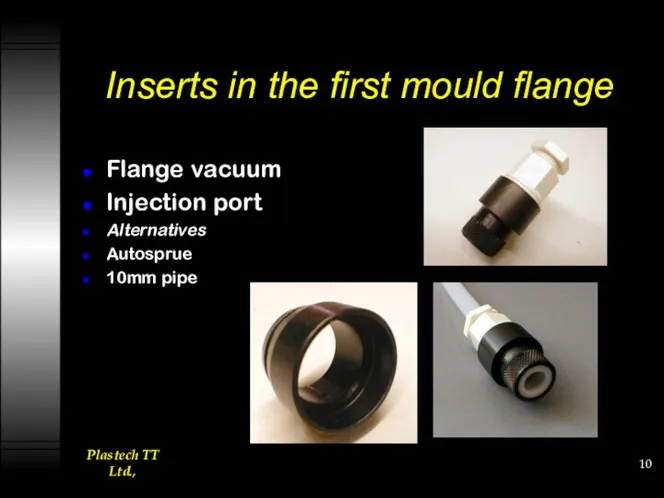
Inserts in the first mould flange
Flange vacuum
Injection port
Alternatives
Autosprue
10mm pipe
Inserts in the first mould flange
Flange vacuum
Injection port
Alternatives
Autosprue
10mm pipe
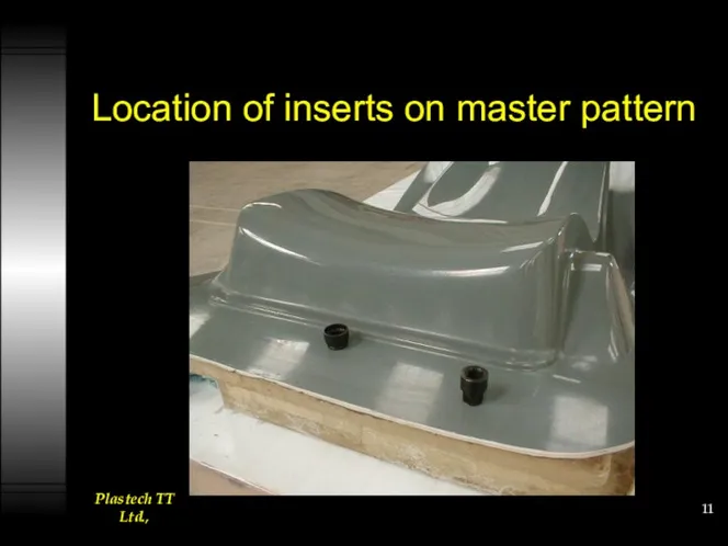
Location of inserts on master pattern
Location of inserts on master pattern
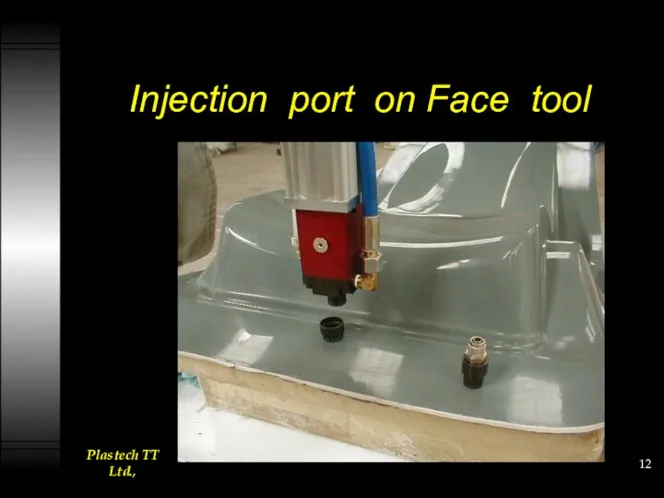
Injection port on Face tool
Injection port on Face tool
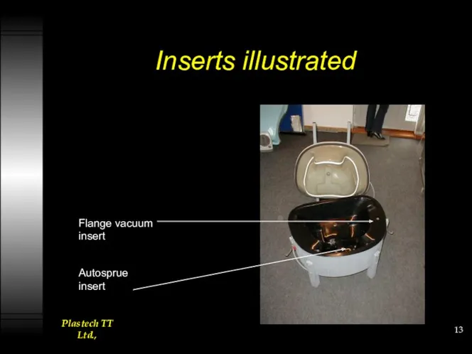
Inserts illustrated
Flange vacuum insert
Autosprue insert
Inserts illustrated
Flange vacuum insert
Autosprue insert
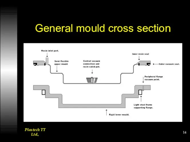
General mould cross section
General mould cross section
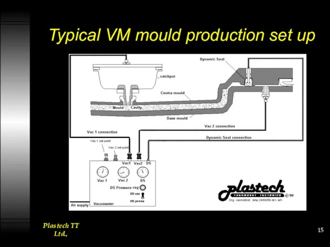
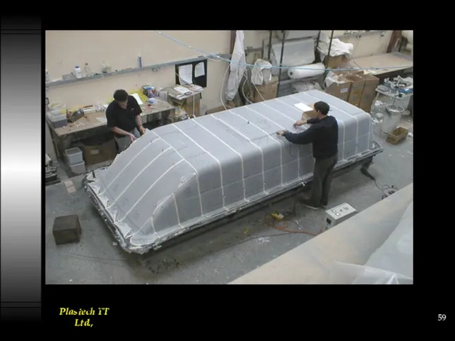
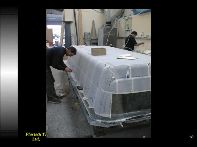
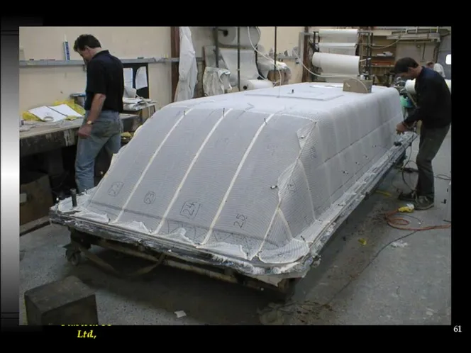
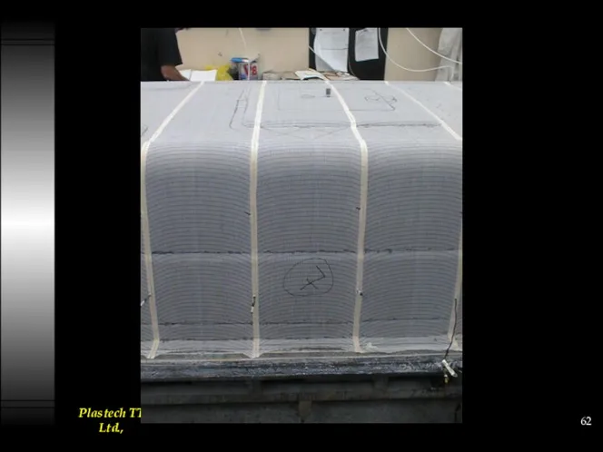
Typical VM mould production set up
Typical VM mould production set up
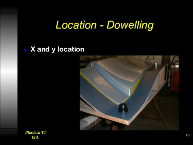
Location - Dowelling
X and y location
Location - Dowelling
X and y location
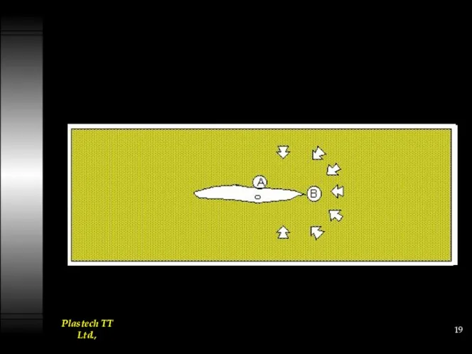
Peripheral Fill
Resin mould flow designed to find initial easy path around
Peripheral Fill
Resin mould flow designed to find initial easy path around
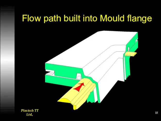
Flow path built into Mould flange
Flow path built into Mould flange
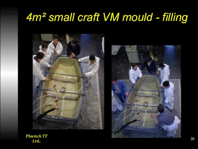
4m² small craft VM mould - filling
4m² small craft VM mould - filling
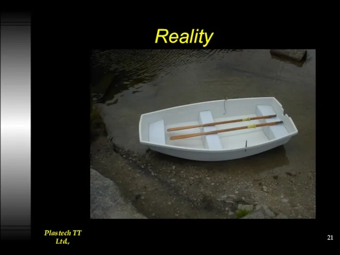
Reality
Reality
More Flow shots
More Flow shots
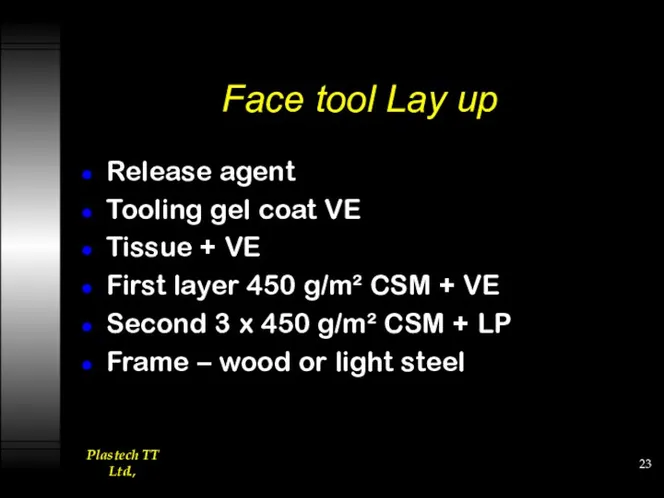
Face tool Lay up
Release agent
Tooling gel coat VE
Tissue + VE
First layer
Face tool Lay up
Release agent
Tooling gel coat VE
Tissue + VE
First layer
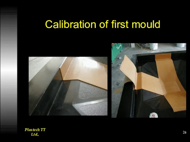
Calibration of first mould
Calibration of first mould
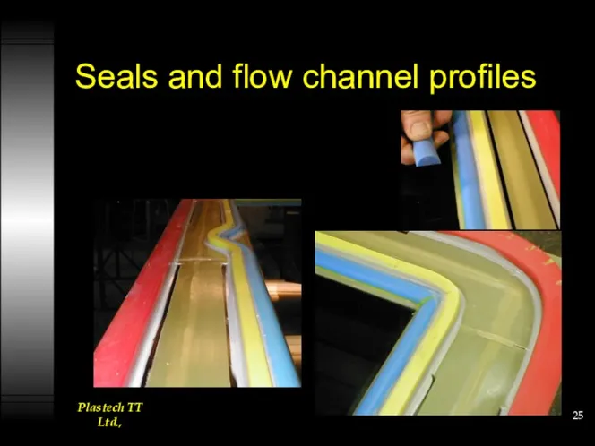
Seals and flow channel profiles
Seals and flow channel profiles
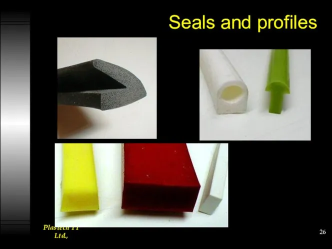
Seals and profiles
Seals and profiles
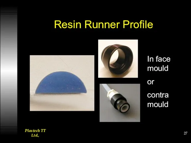
Resin Runner Profile
In face mould
or
contra mould
Resin Runner Profile
In face mould
or
contra mould
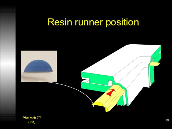
Resin runner position
Resin runner position
Two vacuum levels
Vacuum 1 to clamp mould flange.
At least 85%
Two vacuum levels
Vacuum 1 to clamp mould flange.
At least 85%
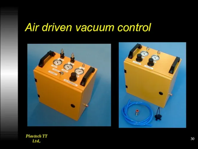
Air driven vacuum control
Air driven vacuum control
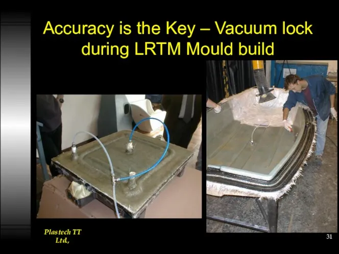
Accuracy is the Key – Vacuum lock during LRTM Mould build
Accuracy is the Key – Vacuum lock during LRTM Mould build
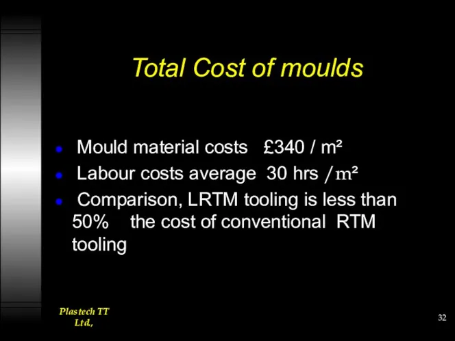
Total Cost of moulds
Mould material costs £340 / m²
Labour
Total Cost of moulds
Mould material costs £340 / m²
Labour
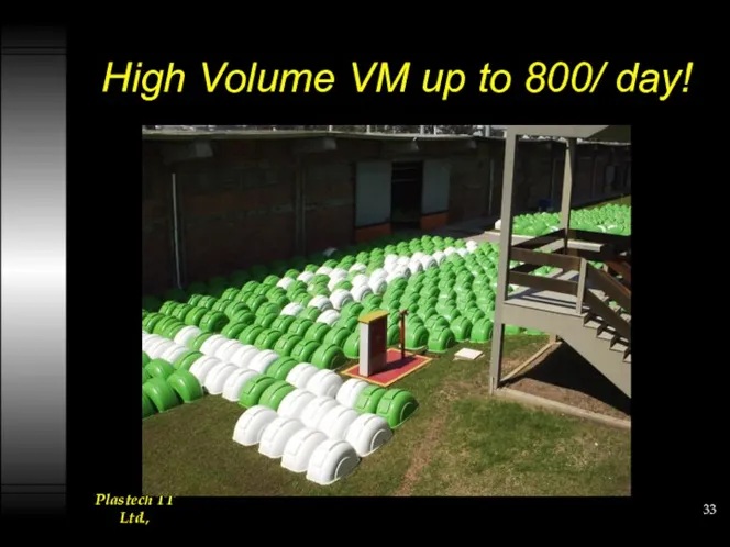
High Volume VM up to 800/ day!
High Volume VM up to 800/ day!
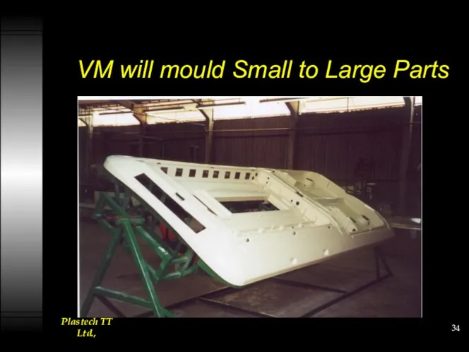
VM will mould Small to Large Parts
VM will mould Small to Large Parts

LRTM can go big and complicated
LRTM can go big and complicated
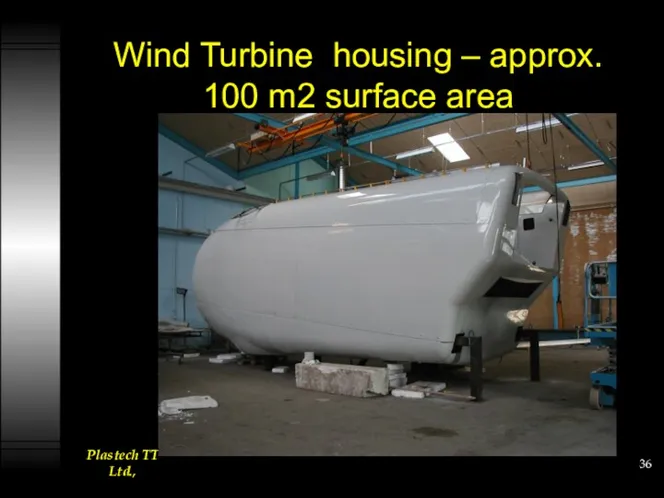
Wind Turbine housing – approx. 100 m2 surface area
Wind Turbine housing – approx. 100 m2 surface area
Difference between RTM and LRTM
Moulding Speed
Moulding accuracy
Equipment requirements
Difference between RTM and LRTM
Moulding Speed
Moulding accuracy
Equipment requirements
“RTM” and complimentary “LRTM” closed moulding for composites
Difference between RTM
“RTM” and complimentary “LRTM” closed moulding for composites
Difference between RTM
Moulding Speed
LRTM injects the fibre pack at approximately 1/3 the speed
Moulding Speed
LRTM injects the fibre pack at approximately 1/3 the speed
“RTM” and complimentary “LRTM” closed moulding for composites
Difference between RTM
“RTM” and complimentary “LRTM” closed moulding for composites
Difference between RTM
Moulding Accuracy
LRTM moulds within +/- 0.025”at best
RTM moulds within +/- 0.002”
Moulding Accuracy
LRTM moulds within +/- 0.025”at best
RTM moulds within +/- 0.002”
“RTM” and complimentary “LRTM” closed moulding for composites
Difference between RTM
“RTM” and complimentary “LRTM” closed moulding for composites
Difference between RTM
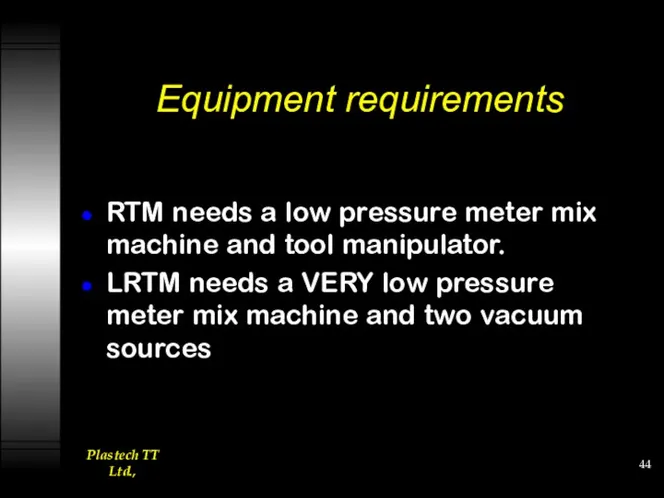
Equipment requirements
RTM needs a low pressure meter mix machine and tool
Equipment requirements
RTM needs a low pressure meter mix machine and tool
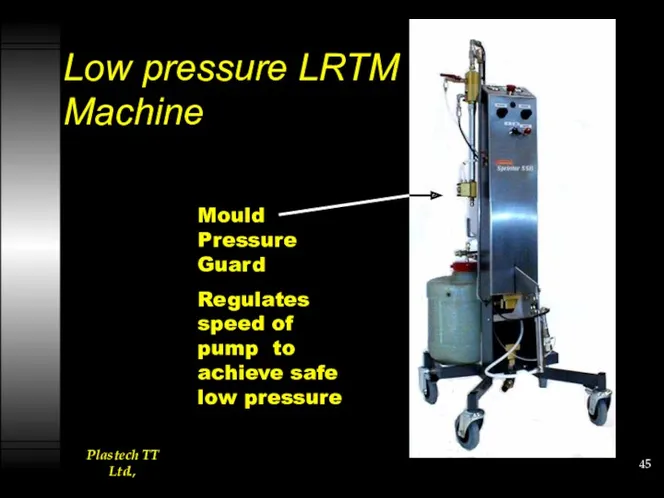
Low pressure LRTM Machine
Mould Pressure Guard
Regulates speed of pump
Low pressure LRTM Machine
Mould Pressure Guard
Regulates speed of pump
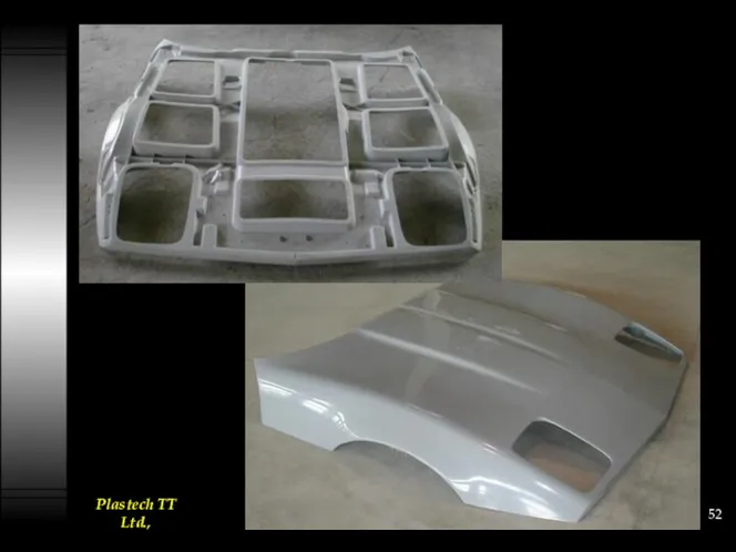
More Application examples
More Application examples
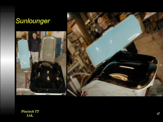
Sunlounger
Sunlounger
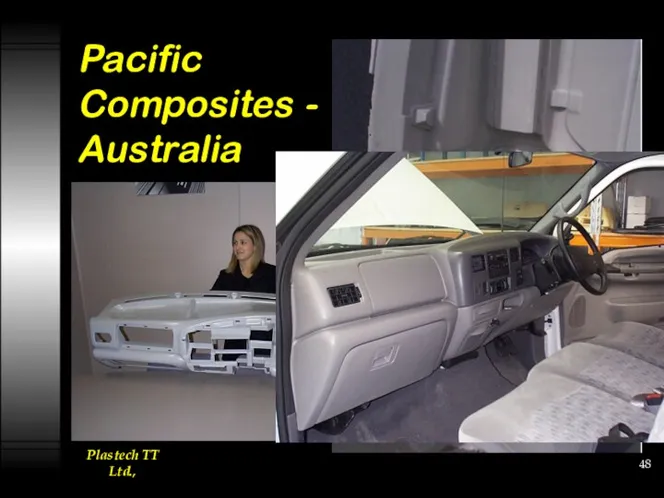
Pacific Composites - Australia
Pacific Composites - Australia
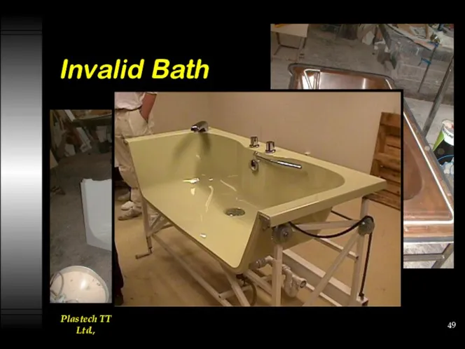
Invalid Bath
Invalid Bath
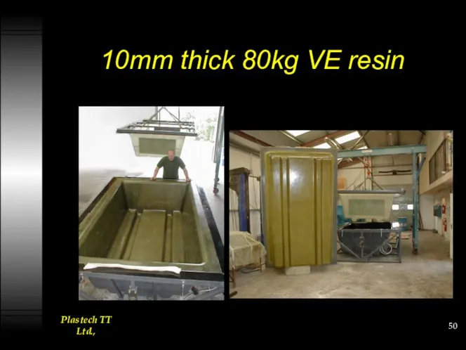
10mm thick 80kg VE resin
10mm thick 80kg VE resin
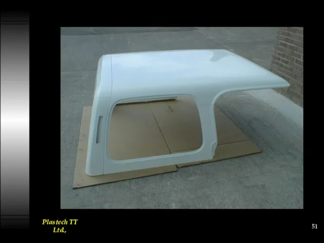
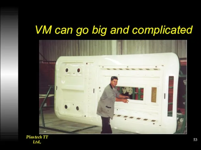
VM can go big and complicated
VM can go big and complicated
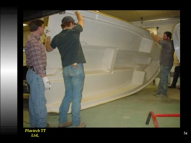
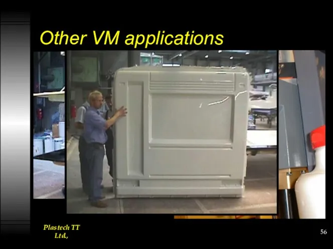
Other VM applications
Other VM applications
Conclusions
LRTM is a viable lower cost system complimentary to RTM.
Tooling manufacture
Conclusions
LRTM is a viable lower cost system complimentary to RTM.
Tooling manufacture
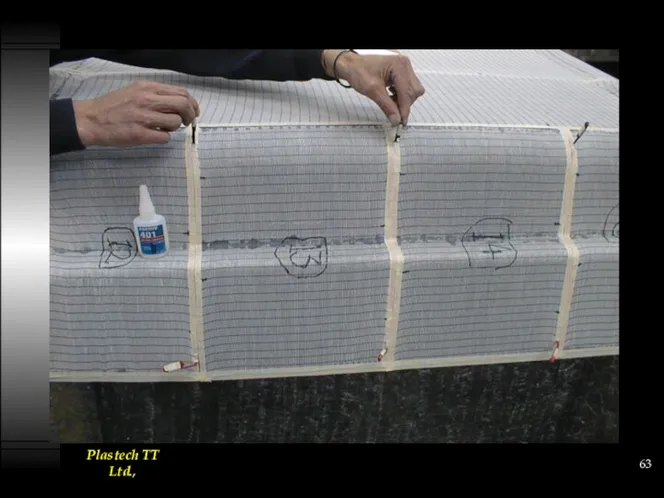
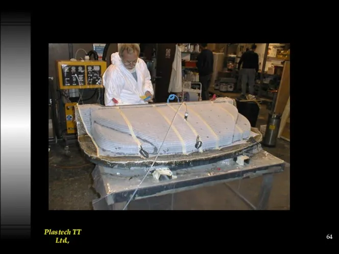
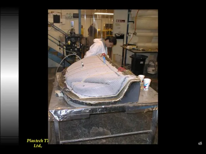
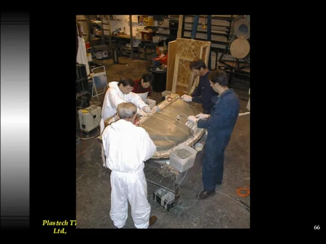
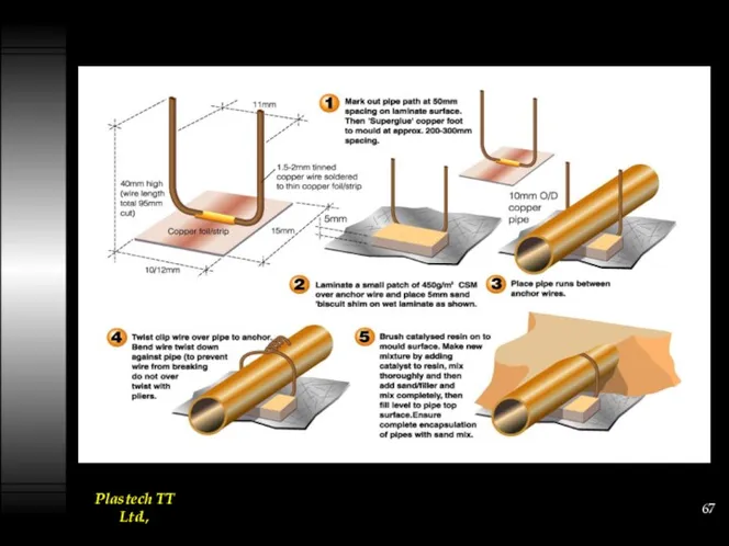
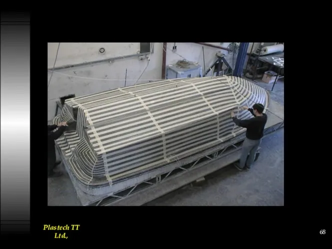
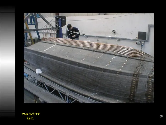
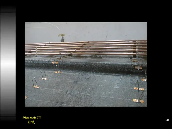
Heating /Temperature control
Heating /Temperature control
Electrical Heater-Cloth Application.
Electrical Heater-Cloth Application.
 Вибрационная болезнь (0)
 Сравнительный анализ и методика повышения эффективности дистанционных бросков у баскетболистов разной квалификации
 Границы аэробноанаэробного перехода: АП-1, АнП-2
 Флотационные реагенты, применяемые при флотации руд редких и благородных металлов
 Организации в экономике
 Бизнес – проект по развитию садоводства
 Западная геополитика после II Мировой войны (часть 2)
 Бауыр және өт жолдары, ұйқы безі ауруларын тағаммен емдеу және емдік дене шынықтыру
 Интегральные характеристики светового поля. Средние освещенности по поверхности
 Осуществление образовательной деятельности в игре
 Презентация Проблемы молодежи
 Презентация внекласного мероприятия Моя Кызылорда
 презентация портфолио ученика
 Введение в химию. 8 класс
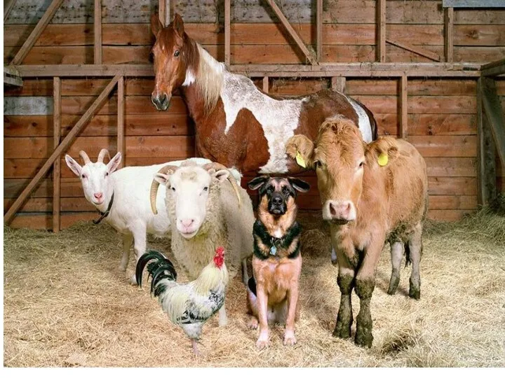 Овцеводство и свиноводство
 Обеспечение предприятий автосервиса материально-техническими ресурсами. Материальные ресурсы. (Тема 9.15)
 Методы вторичного вскрытия пласта
 Электрические аппараты электровозов. Классификация
 Розширена колегія Державного агентства лісових ресурсів України за 1 півріччя 2019 року
 Классный час СНГ-Содружество Независимых Государств
 Презентация Лягушка - зелёное брюшко (сказочная история для язычка)
 Безопасность в сети интернет
 Лукьянова О. СОШ 30Scientists and their discoveries that changed the world
 Определение кадастровой стоимости
 Презентация по технологии 1 класс на тему Кораблик
 Заготовка древесины, ее пороки и выбор для изготовления изделий
 Основы светской этики. Урок-презентация Свобода и моральный выбор человека
 New technologies