- Message signaled interrupts

Содержание
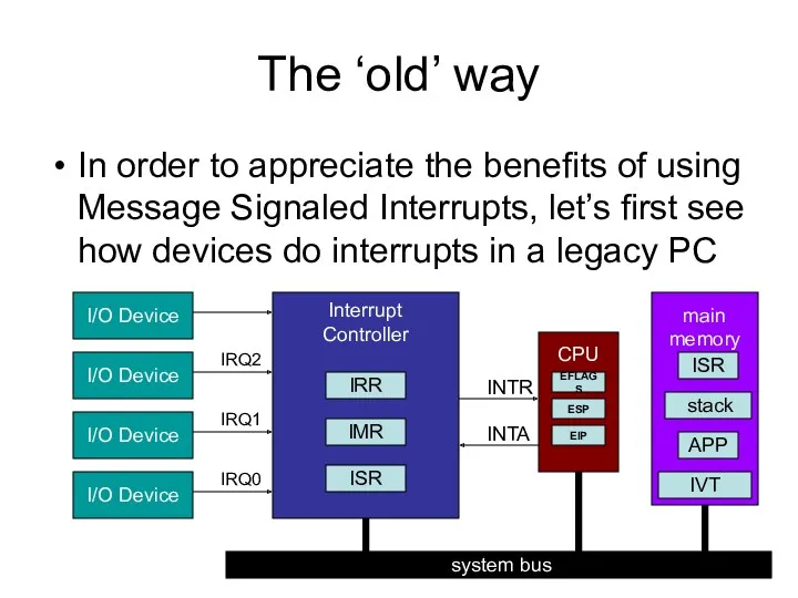
- 2. The ‘old’ way In order to appreciate the benefits of using Message Signaled Interrupts, let’s first
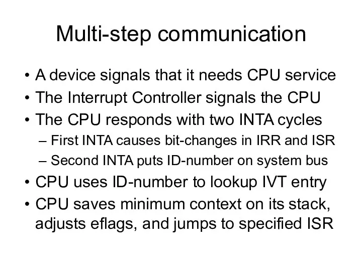
- 3. Multi-step communication A device signals that it needs CPU service The Interrupt Controller signals the CPU
- 4. Faster, cheaper, and more Faster response to interrupts is possible if the old multi-step communication scheme
- 5. The ‘new’ way Message Signaling allows all the needed information to arrive in a single package,
- 6. Implementation The customary PCI Configuration Space is modified to accommodate three additional registers, which collectively are
- 7. PCI Command Register 15 10 9 8 7 6 5 4 3 2 1 0 Interrupt
- 8. PCI Status Register 15 14 13 12 11 10 9 8 7 6 5 4 3
- 9. MSI Control Register reserved 1 0 0 0 0 0 0 0 15 8 7 6
- 10. MSI Address Register 0 0 0 0 0 0 0 0 0 0 0 0 0
- 11. MSI Data Register reserved reserved 31 16 15 14 11 8 7 0 vector Delivery Mode
- 12. Recall NIC’s interrupt registers enum { E1000_ICR = 0x00C0, // Interrupt Cause Read E1000_ICS = 0x00C8,
- 13. Demo module: ‘msidemo.c’ This module installs an interrupt-handler for an otherwise unused interrupt-vector It initializes the
- 15. Скачать презентацию
The ‘old’ way
In order to appreciate the benefits of using Message
The ‘old’ way
In order to appreciate the benefits of using Message
Multi-step communication
A device signals that it needs CPU service
The Interrupt Controller
Multi-step communication
A device signals that it needs CPU service
The Interrupt Controller
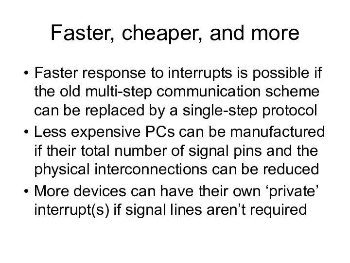
Faster, cheaper, and more
Faster response to interrupts is possible if the
Faster, cheaper, and more
Faster response to interrupts is possible if the
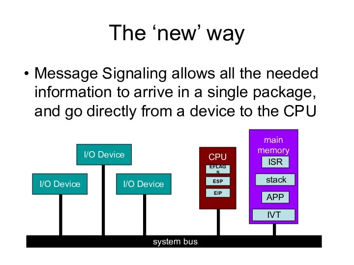
The ‘new’ way
Message Signaling allows all the needed information to arrive
The ‘new’ way
Message Signaling allows all the needed information to arrive
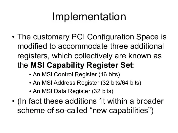
Implementation
The customary PCI Configuration Space is modified to accommodate three additional
Implementation
The customary PCI Configuration Space is modified to accommodate three additional
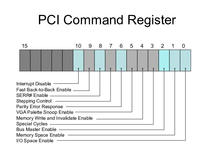
PCI Command Register
15 10 9 8 7 6 5 4
PCI Command Register
15 10 9 8 7 6 5 4
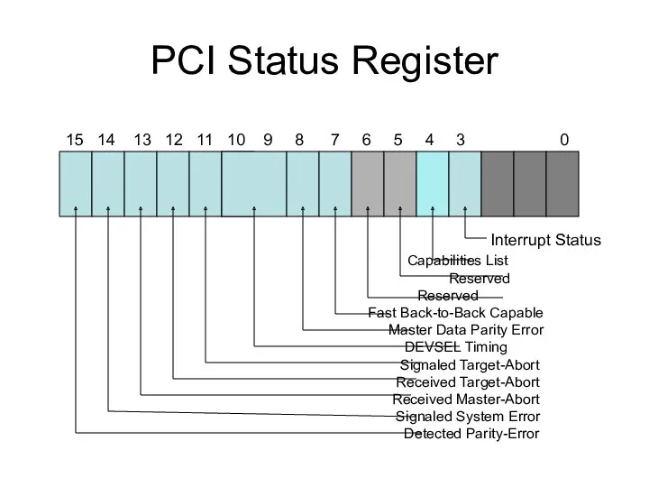
PCI Status Register
15 14 13 12 11 10 9
PCI Status Register
15 14 13 12 11 10 9
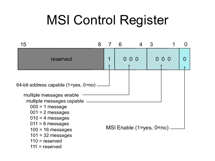
MSI Control Register
reserved
1
0 0 0
0 0 0
0
15 8
MSI Control Register
reserved
1
0 0 0
0 0 0
0
15 8
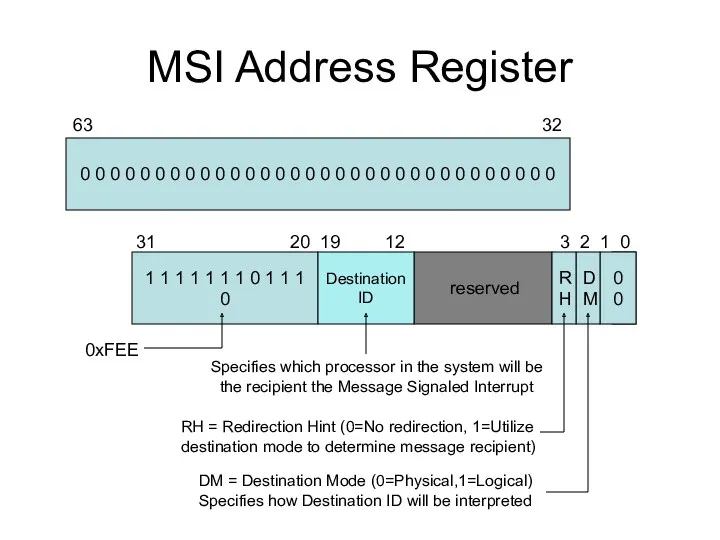
MSI Address Register
0 0 0 0 0 0 0 0 0
MSI Address Register
0 0 0 0 0 0 0 0 0
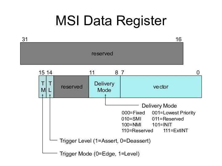
MSI Data Register
reserved
reserved
31 16
15
MSI Data Register
reserved
reserved
31 16
15
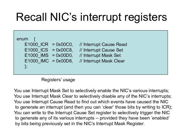
Recall NIC’s interrupt registers
enum {
E1000_ICR = 0x00C0, // Interrupt Cause Read
E1000_ICS = 0x00C8, // Interrupt
Recall NIC’s interrupt registers
enum {
E1000_ICR = 0x00C0, // Interrupt Cause Read
E1000_ICS = 0x00C8, // Interrupt
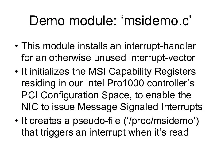
Demo module: ‘msidemo.c’
This module installs an interrupt-handler for an otherwise unused
Demo module: ‘msidemo.c’
This module installs an interrupt-handler for an otherwise unused
 Простейшие грузоподъемные устройства и механизмы. Лекция 2
 Готовимся к ОГЭ-2018
 Родительское собрание Первые школьные отметки 2 класс Диск
 Тема: Взаимодействие с родителями по проекту Дети в музее
 Кислоты
 Развитие языковых способностей дошкольников
 Віруси геморагічних гарячок: клінічні прояви, діагноз, лікування та профілактика
 Biological method of research
 Классный час Пасха
 Презентация - Требования к речи педагога
 Обзор грантовых конкурсов
 Ас қорыту жүйесінің визуальды диагностикасы
 Основные реабилитационные направления при детском церебральном параличе
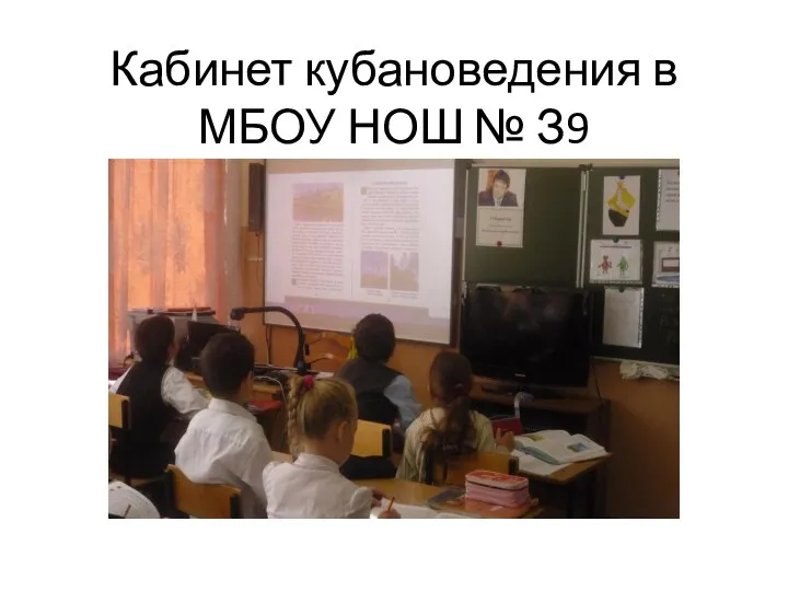 Презентация Кабинет кубановедения
 Архитектура типового Enterprise приложения
 Somebody That I Used To Know
 Размещение инфрмации в соц.сетях Копейка
 Презентация Спирты
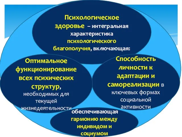 Психологическое здоровье
 Листовка для расклейки на предприятии. Тарифы
 Порядок предоставления в электронной форме услуги Государственная экспертиза проектной документации
 Мега галактический театр. Игровой урок-повторение для 1 класса по школьной программе
 Сочинение – описание по картине В. М. Васнецова Алёнушка. 6 класс
 Сучасна географія виробництва транспортних засобів
 Процесуальний порядок проведення технічної інвентаризації об’єктів нерухомого майна (Тема 4)
 Маршрутная сеть Кировского района города Перми
 Риски пренатального развития
 Кирилл и Мефодий. Гимн и Величание